Focusing Light with Curved Guided-Mode Resonance Reflectors

1
Department of Electrical Engineering, University of Texas at Arlington, 416 Yates Street, Arlington, TX 76019, USA
2
School of Electronic Engineering, Xidian University, Xi’an, Shannxi 710071, China
*
Author to whom correspondence should be addressed.
Micromachines 2011, 2(2), 150-156; https://doi.org/10.3390/mi2020150
Submission received: 2 March 2011
/
Revised: 12 April 2011
/
Accepted: 14 April 2011
/
Published: 28 April 2011
(This article belongs to the Special Issue Nano-photonic Devices)
Abstract
:Employing numerical simulations, we investigate the possibility of using curved guided-mode resonance (GMR) elements to focus light in reflection. We treat GMR reflectors with a parabolic shape and show that they are capable of focusing light effectively across wavelength bands that extend several hundred nanometers. The spatially infinite reflector model is simulated with a finite-element method, whereas the spatially finite reflector is treated with a finite-difference-time-domain method. The numerical results demonstrate that light intensity at the focal point is 8.6 dB stronger than the incident intensity when the GMR reflector's size is on the order of 10 wavelengths. The results indicate potential applicability of wideband-focusing devices in electromagnetics and photonics using compact resonance elements.
1. Introduction
Focusing light and electromagnetic waves is important in a host of applications. For instance, parabolic metallic reflectors are widely adopted to focus electromagnetic waves in microwave engineering, and various antenna designs integrate spherical reflectors and paraboloidal/parabolic reflectors [1,2]. In optics, concave surfaces serve to focus light [3,4]. In integrated optics, a waveguide mode can be coupled out and focused using planar focusing grating couplers where the period of the grating is spatially modulated (i.e., chirped) [5]. On account of fabrication difficulty, curved focusing elements have not been widely developed in integrated optics. Nevertheless, for example, the use of curved reflective gratings has been suggested for integrated devices serving as wavelength demultiplexers [6]. In this paper, we investigate a new method for reflective focusing in which the focal point appears on the illumination side. Initial results quantifying the focal performances of an example silicon-based guided-mode resonance (GMR) reflector are presented.
Guided-mode (or equivalently, leaky-mode) resonance takes advantage of periodic dielectric grating structures to create versatile photonic spectra with associated surface-localized energy states [6-10]. These states enable narrow-line bandpass and bandstop filters, polarizers, reflectors, and polarization-independent elements [11]. Since single-layer GMR films with one-dimensional periodicity are light, compact, and easy to fabricate, they have numerous applications including filters, laser mirrors, ultrasensitive biosensors, absorption enhancement in solar cells, security devices, tunable filters, nanoelectromechanical display pixels, and others as suggested in [10-13]. Particularly, it is shown in [14] that flat GMR grating structures can be utilized as focusing reflectors by adjusting the local grating periodicity. All prior research on GMRs employs planar geometries; here, we study GMRs with curved geometries. Specifically, our GMR element is configured along a parabolic curve and designed to behave as a good reflector over a wide spectral band. As a result, upon collimated incidence, this curved GMR focuses light at its focal point.
The GMR structures treated here are simulated by two numerical methods based on finite-element and finite-difference-time-domain for infinite and finite model dimensions, respectively. The computed results corroborate each other well. The numerical results demonstrate that light intensity at the focal point is 8.6 dB stronger than the incident intensity when the GMR reflector's size is only 10 times the size of the wavelength. Therefore, the curved GMR in this paper offers a means to accomplish local light enhancement, which can be applied, for example, in photo detection. We expect this initial work to serve as the foundation for many other applications where reflective light focusing with low-loss dielectric media is advantageous.
2. Design of the Curved GMR Reflector
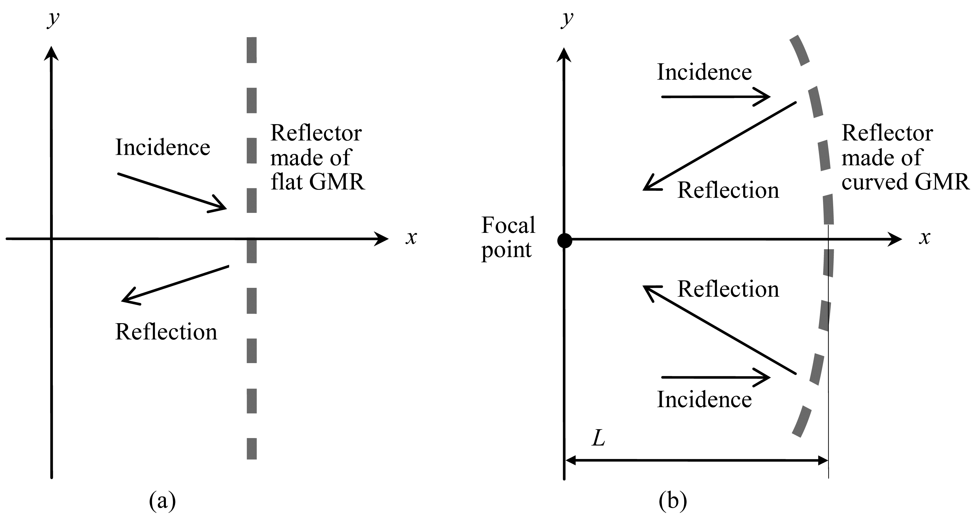
Our curved GMR is based upon a flat GMR design shown in Figure 1(a). The single-layer, flat GMR in Figure 1(a) consists of a homogeneous dielectric slab with periodic perforations. The periodicity exists along the y direction only, and the geometry is assumed unvaried along z. It is well known that the flat GMR in Figure 1(a) can be designed to be a wideband reflector [11]. On the basis of the flat GMR in Figure 1(a), we expect the curved GMR structure in Figure 1(b) to be capable of focusing light. To be specific, the flat GMR structure is reconfigured along a parabolic curve expressed as [2]
In Equation (1), L denotes the focal length. When incident collimated light travels along the +x direction, it is reflected such that all the reflected light rays are constructive at the focal point. Obviously, light focusing requires the GMR to be a good reflector that can accommodate light with a range of incident angles with respect to the GMR's normal direction. This design difficulty can be relieved if L is large; the curved GMR in Figure 1(b) approaches a flat GMR with increasing L. However, a large value of L implies a large device, which is usually undesired. In this study, extensive numerical simulations are carried out to find the appropriate L value to compromise light focusing and the device size.
3. Numerical Results
This section presents numerical results to demonstrate light focusing using curved GMR structures. A planar GMR configuration is designed first, providing a reference wideband reflector accommodating a wide range of incident angles. Then this planar GMR reflector is tailored into a parabolic shape. Therefore, light with normal incidence can be focused onto the focal point of the parabolic GMR reflector.
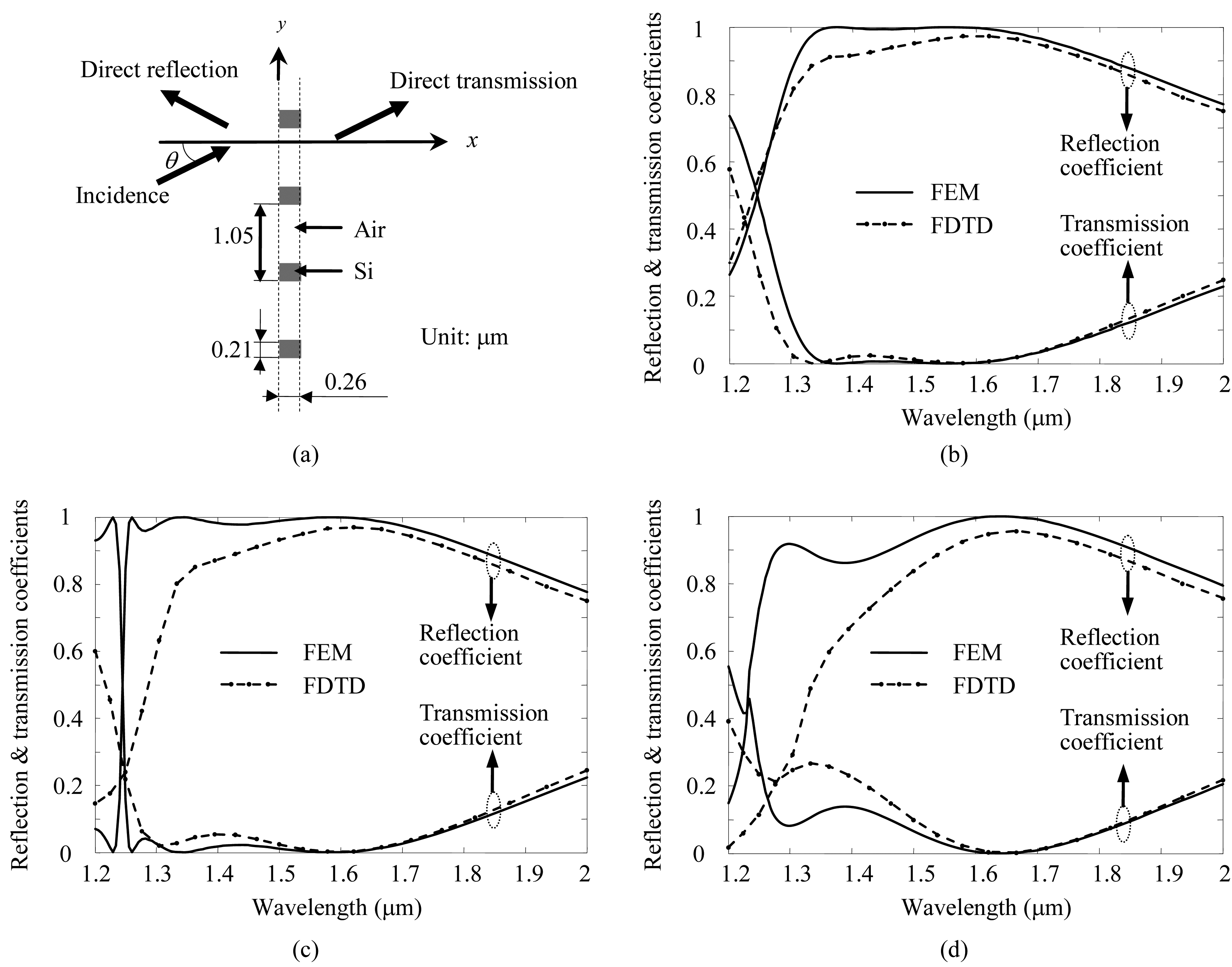
An example planar GMR reflector is illustrated in Figure 2(a). It consists of periodic grating elements made of silicon (Si, with refraction index 3.48) in air. The gratings exhibit no variation along the z direction. The incident light is polarized along z, represented as
where Ei denotes the electric field intensity associated with the incident light, θ stands for the incident angle with respect to the x axis, β0 = ω/c, ω is the angular frequency, c is the speed of light in the air,
, and the ejωt dependence is suppressed. We follow [11] and design the planar GMR structure in Figure 2(a) to be a wideband reflector for a range of incident angles. In reaction to the incident light, we compute amplitudes of reflected electric field Er and transmitted electric field Et expressed as
In Figure 2(b–d), the reflection coefficient
and transmission coefficient
are plotted for three incident angles: θ = 0°, θ = 5°, and θ = 10°. Two numerical methods are applied; one is based on the finite-element method (FEM), and the other is based on the finite-difference-time-domain (FDTD) method. The FEM simulation is carried out in the frequency domain while FDTD is carried out in the time domain. In the FEM computations, the size of geometrical elements (i.e., triangles) is about λ/10 (with λ standing for the wavelength); whereas in FDTD, there are about 25 geometrical elements within λmin, where λmin is the shortest wavelength of concern. The model GMR structure is assumed to have infinite periodic extension along y for the FEM study, while the FDTD simulation assumes 20 periods (i.e., it constitutes a finite GMR structure that is only 21 μm wide from edge to edge). Results from these two substantially different simulation methods match each other rather well as shown in Figure 2(b–d). Moreover, we compared the FEM results with computed results using rigorous coupled-wave analysis (RCWA) [15] and found perfect agreement. Based on these results, in practice we would apply somewhat larger arrays to enhance device efficiency. For all three incident angles, the planar GMR structure behaves as a wideband reflector. It is observed that the reflection coefficient is greater than 75% when the wavelength is in the range (1.5 μm, 2 μm) for all three incident angles.
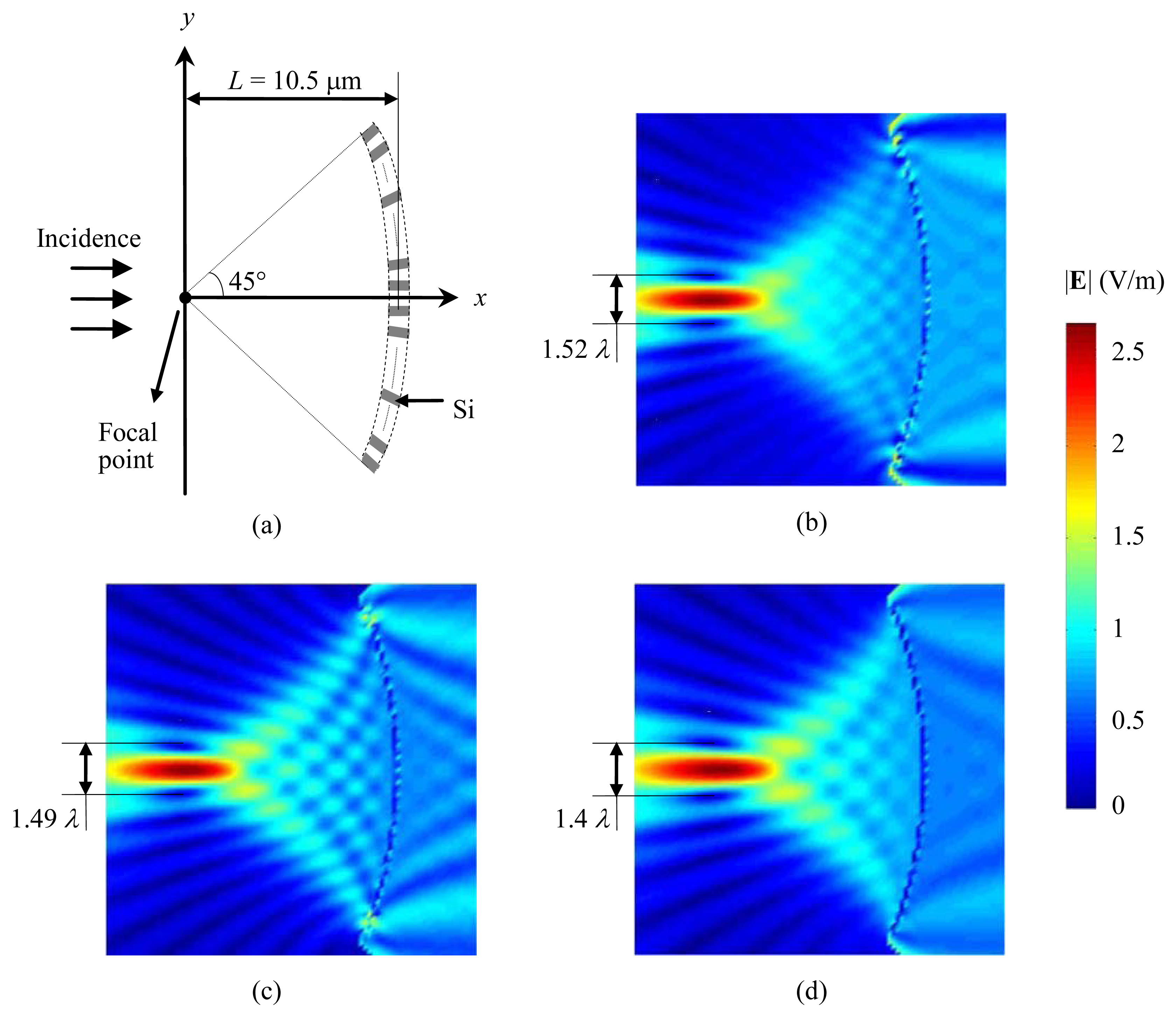
In Figure 3(a), the planar gratings shown in Figure 2(a) are deployed along a parabolic curve with L = 10.5 μm. In total, there are 28 grating elements in the parabolic GMR reflector in Figure 3(a); the parabolic surface extends along ∼29 μm. The incident light is expressed in Equation (2) with θ = 0° (that is, along the x direction). Since the GMR structure is a wideband reflector for a range of incident angles, we expect the light with normal incidence to focus onto the focal point. The focusing phenomenon is demonstrated by the numerical results using FDTD in Figure 3(b–d). For the purpose of clear visualization, the electric field intensity is plotted in a region around the GMR reflector using different colors, with the incident electric field subtracted. The field is observed to be focused at the focal point, and the particular device under study can accommodate a relatively wide spectral range of several hundreds of nanometers. Over the focal plane, the distance between the two locations with zero field intensity next to the focal point is about 1.5 wavelengths, which means that the focusing performance of the proposed parabolic GMR reflector is consistent with the diffraction limit. For the three selected wavelengths in Figure 3(b–d), the field intensity at the focal point is at least 8.6 dB higher than the incident light. In order to further reveal the focusing capability of our curved GMR device, simulation is conducted when the GMR reflector is replaced by a perfect reflector (in other words, the parabolic reflector in Figure 3 is assumed to be made of a perfect electric conductor). As the fictitious, perfect reflector offers unprecedented focusing performance, thus it is used as a reference to evaluate our GMR device. It is found that light intensity at the focal point with a perfect reflector is about 4 dB greater than that associated with our GMR reflector, demonstrating that the GMR reflector is an effective focusing mirror.
4. Conclusions
In summary, by numerical modeling, we demonstrate that parabolic GMR reflectors are capable of focusing light effectively. Specifically, our simulation results show that light intensity at the focal point is 8.6 dB stronger than the incident intensity when the GMR reflector is approximately 10 wavelengths across. Fabrication of the curved GMR structures proposed here is feasible by using electron-beam patterning followed by deep reactive-ion etching, which results in silicon pillars in air that can be tested by illumination with collimated laser beams. Incorporation of the pillars in a lower-index medium that serves additionally as an input-light waveguide is also possible; in this latter case, the refractive-index contrast, and thus the mirror bandwidth, would diminish.
Figure 1.
Illustration of (a) flat GMR reflector and (b) curved GMR reflector.

Figure 2.
Numerical results for a planar GMR structure: (a) Geometry, (b) Results when θ = 0°, (c) Results when θ = 5°, (d) Results when θ = 10°.
Figure 2.
Numerical results for a planar GMR structure: (a) Geometry, (b) Results when θ = 0°, (c) Results when θ = 5°, (d) Results when θ = 10°.

Figure 3.
Numerical results for a curved GMR structure: (a) Schematic rendition of device geometry, (b) Results for wavelength λ = 1.69 μm, (c) Results for wavelength λ = 1.76 μm, (d) Results for wavelength λ = 2 μm.
Figure 3.
Numerical results for a curved GMR structure: (a) Schematic rendition of device geometry, (b) Results for wavelength λ = 1.69 μm, (c) Results for wavelength λ = 1.76 μm, (d) Results for wavelength λ = 2 μm.

Acknowledgments
This work was supported in part by the UT System Texas Nanoelectronics Research Superiority Award funded by the State of Texas Emerging Technology Fund. Additional support was provided by the Texas Instruments Distinguished University Chair in Nanoelectronics endowment. The authors would like to acknowledge Texas Advanced Computing Center (TACC) for granting access to its computational facilities.
References
- Xu, S.; Rahmat-Samii, Y. A novel beam squint compensation technique for circularly polarized conic-section reflector antennas. IEEE Trans. Antenn. Propag. 2010, 58, 307–317. [Google Scholar]
- Balanis, C.A. Antenna Theory: Analysis and Design, 3rd ed.; Wiley-Interscience: Malden, MA, USA, 2005. [Google Scholar]
- Khoo, E.H.; Liu, A.Q.; Cheng, T.H.; Li, J.; Pinjala, D. Light focusing via Rowland concave surface of photonic crystal. Appl. Phys. Lett. 2007, 91, 221105. [Google Scholar]
- Burke, J.; Green, K.; Stuart, W.; Puhanic, E.; Leistner, A.; Oreb, B. Fabrication and testing of a high-precision concave spherical mirror. Proc. SPIE 2008, 7064, 70640E. [Google Scholar]
- Nishihara, H.; Haruna, M.; Suhara, T. Optical Integrated Circuits; McGraw-Hill Book Company: New York, NY, USA, 1989. [Google Scholar]
- Vincent, P.; Neviere, M. Corrugated dielectric waveguides: A numerical study of the second-order stop bands. Appl. Phys. A Mater. Sci. Process. 1979, 20, 345–351. [Google Scholar]
- Mashev, L.; Popov, E. Zero order anomaly of dielectric coated gratings. Opt. Commun. 1985, 55, 377–380. [Google Scholar]
- Avrutsky, I.A.; Sychugov, V.A. Reflection of a beam of finite size from a corrugated waveguide. J. Modern Opt. 1989, 36, 1527–1539. [Google Scholar]
- Golubenko, G.A.; Svakhin, A.S.; Sychugov, V.A.; Tishchenko, A.V. Total reflection of light from a corrugated surface of a dielectric waveguide. Soviet J. Quant. Electr. 1985, 15, 886–887. [Google Scholar]
- Wang, S.S.; Magnusson, R. Theory and applications of guided-mode resonance filters. Appl. Opt. 1993, 32, 2606–2613. [Google Scholar]
- Ding, Y.; Magnusson, R. Resonant leaky-mode spectral-band engineering and device applications. Opt. Express 2004, 12, 5661–5674. [Google Scholar]
- Magnusson, R.; Ding, Y.; Lee, K.J.; Shin, D.; Priambodo, P.S.; Young, P.P.; Maldonado, T.A. Photonic devices enabled by waveguide-mode resonance effects in periodically modulated films. Proc. SPIE 2003, 5225, 20–34. [Google Scholar]
- Magnusson, R.; Shokooh-Saremi, M. Physical basis for wideband resonant reflectors. Opt. Express 2008, 16, 3456–3462. [Google Scholar]
- Fattal, D.; Li, J.; Peng, Z.; Fiorentino, M.; Beausoleil, R.G. Flat dielectric grating reflectors with focusing abilities. Nat. Photonics 2010, 4, 466–470. [Google Scholar]
- Gaylord, T.K.; Moharam, M.G. Analysis and applications of optical diffraction by gratings. Proc. IEEE 1985, 73, 894–937. [Google Scholar]
© 2011 by the authors; licensee MDPI, Basel, Switzerland. This article is an open access article distributed under the terms and conditions of the Creative Commons Attribution license (http://creativecommons.org/licenses/by/3.0/).
Share and Cite
MDPI and ACS Style
Lu, M.; Zhai, H.; Magnusson, R. Focusing Light with Curved Guided-Mode Resonance Reflectors. Micromachines 2011, 2, 150-156. https://doi.org/10.3390/mi2020150
AMA Style
Lu M, Zhai H, Magnusson R. Focusing Light with Curved Guided-Mode Resonance Reflectors. Micromachines. 2011; 2(2):150-156. https://doi.org/10.3390/mi2020150
Chicago/Turabian StyleLu, Mingyu, Huiqing Zhai, and Robert Magnusson. 2011. "Focusing Light with Curved Guided-Mode Resonance Reflectors" Micromachines 2, no. 2: 150-156. https://doi.org/10.3390/mi2020150