Jitterbot: A Mobile Millirobot Using Vibration Actuation

Abstract
: Microrobotics is a rapidly growing field with promising applications in microsurgery and microassembly. A challenge in these systems is providing power and control signals to the robot. This project explores crawling robots that are powered and controlled through a global mechanical vibration field. Structures within the robot will cause it to respond to particular frequencies with different motion modalities. A prototype, dubbed the “jitterbot”, was cut out of a 0.75 mm sheet of steel using electric discharge machining (EDM), and has a total footprint of approximately 30 mm × 20 mm in the xy-plane. The “robot” has a tripod body (8 mm × 16 mm) with three small legs, and two suspended masses that are designed for specific resonance frequencies. The robot was tested on a plate that was vibrated vertically at frequencies ranging from 20 to 2,000 Hz. For particular resonant frequencies, the robot moves forward and turns in either a clockwise or counterclockwise direction. Finite element modeling confirms that the mechanism for motion is a rocking mode that is influenced by two arms that are suspended mass springs tuned to different frequencies. This lays the groundwork for further miniaturization.1. Introduction
Microrobotics has promising applications in microsurgery and microassembly [1,2]. A challenge in these systems is power and communication between the macro-world and the robot. One approach is to place the robots into a global power field. Such power fields can be electrostatic [3], magnetic [4,5], or vibrational or “seismic” [6-8]. Control signals can be conveyed through the frequency components of the energy field.
Compared to electrostatic and magnetic actuation, vibrational actuation does not perform as well at the microscopic level because of the dominance at that scale of surface forces—such as friction—over inertial forces. However, there are also significant potential advantages to seismic actuation, particularly in medical applications. Magnetic microrobots are already effectively leveraging existing magnetic imaging systems for control and visualization [9]. Scaled appropriately, vibrational actuation might be adapted to use existing ultrasonic imaging systems, which are more affordable and less hazardous than magnetic imaging systems.
In previous work, researchers have developed seismically actuated microrobots using specialized fabrication processes [6-8]. These robots were at the millimeter size scale, had resonant frequencies ranging from hundreds of Hertz to 10 kHz, and had velocities on the order of mm/s. These robots did not perform as reliably as other microrobots based on other actuation mechanisms, and the work was not continued. Further, the physics of these robots was not well understood because of the complexity of the geometry and the uncertainties with frictional forces at the microscale.
The goal of this work is to better understand vibrational actuation in order to facilitate the design of a better seismic microrobot. To that end, we have built a meso-scale robot based on an extruded geometry body form that is compatible with downscaling to a multiuser microfabrication process. The meso-scale was favored for this study because of the more rapid prototyping cycle (days to weeks, as compared to months for a microfabricated structure), and the relative ease of observation. The results of this study will be used to design a seismic robot at sub-millimeter dimensions.
2. Theory of Operation and Prototyping
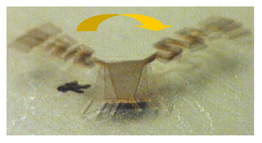
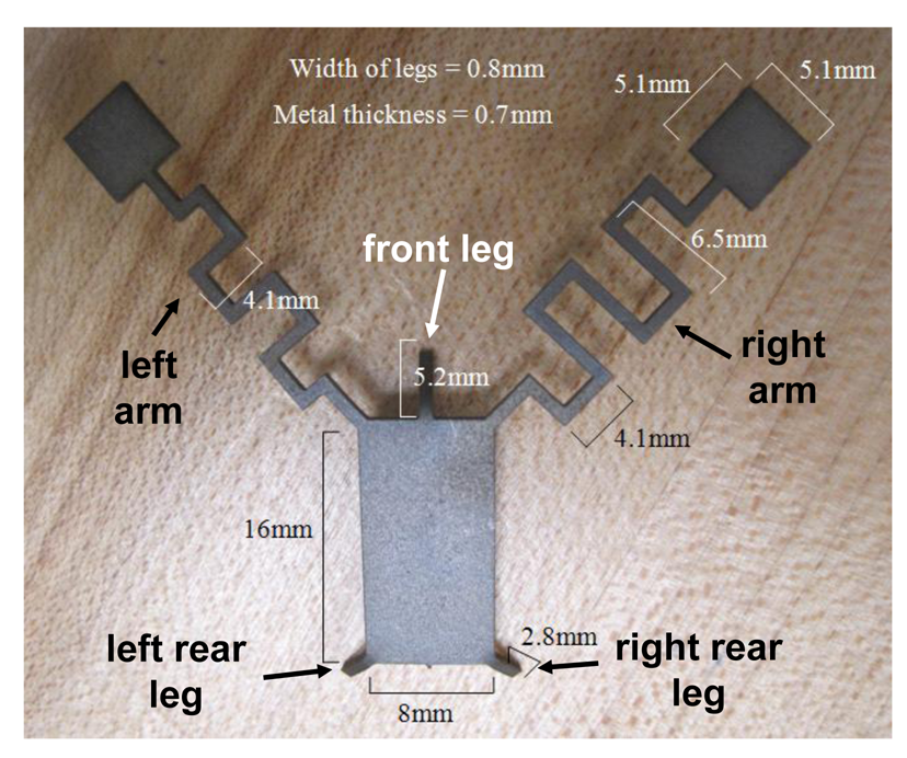
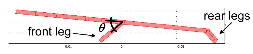
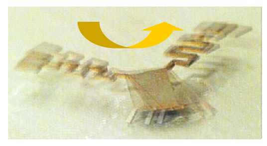
The meso-scale prototype, dubbed the “jitterbot” has a rectangular body with two extending arms, each of which has a smaller mass, or “hand,” attached on its end. This can be seen in Figure 1. The body has three supporting legs, two of which on the back are half as long as the leg in the front, which tilts the robot backwards, as is shown in Figure 2.
The arms and body together act as a mass-spring system to propel the robot in the x-y plane in response to vertical vibration at certain resonant frequencies. The arms are twisted in a serpentine shape to achieve a smaller spring constant for a given footprint. The right arm is effectively longer resulting in a lower resonant frequency. The mechanism for the transduction of vibrational energy into translation is as follows. When one arm is resonating with sufficient energy, it will rock the tripod body. Translation requires non-reciprocal motion. As the resonating arm extends and bends, the center of mass shifts in the direction of the arm, causing the robot to rock up onto the corners of the two contacting legs and translate towards the resonating arm. In the return motion, as the robot rocks back, the entire edge of the opposite foot comes into contact with the surface increasing the effective friction coefficient. The net result is translation in the direction of the oscillating arm. This type of stick-slip motion has been used by other microrobots [3-5,10].
The thickness and minimum dimension for the jitterbot were set by machining limitations. Within these constraints, the arm dimensions were then determined using a lumped-element mass-spring model for the arms in which the body was assumed to be fixed and the mass of the arm consolidated in the “hand.” Using this simplified model the fundamental right and left arm resonances were set to 200 and 300 Hz, respectively, which were chosen to be well below the limitations of the shaker test assembly. The arms were set at 45° to the body in order to equally facilitate forward and turning motion, and the body angle was designed to be at about 45° because of the desire to translate z-axis motion into translation in the x-y plane.
The robot was formed out of a 1018 Steel plate using electron discharge machining. For the first jitterbot, which was formed out of steel that was 0.7 mm thick, the body was 16 mm × 8 mm and the hands were 5 mm × 5 mm. The right arm was about 50 mm in length and the left arm was about 40 mm in length. Both arms were 0.8 mm wide, and angled at 45 degrees to the main body. The front leg was 5.2 mm long and the back legs were 2.8 mm long. The front leg was initially angled 55 degrees down from the body plane, and the back legs are angled about 35 degrees down from the body plane. The vibration field was created using a steel plate mounted on an electrodynamic shaker, which was controlled by the amplified voltage signal from a function generator.
3. Finite Element Model Results
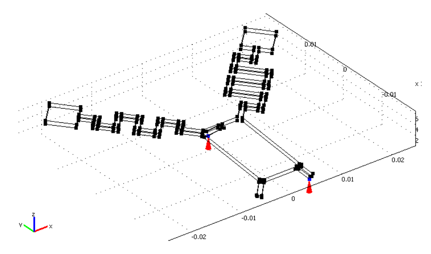
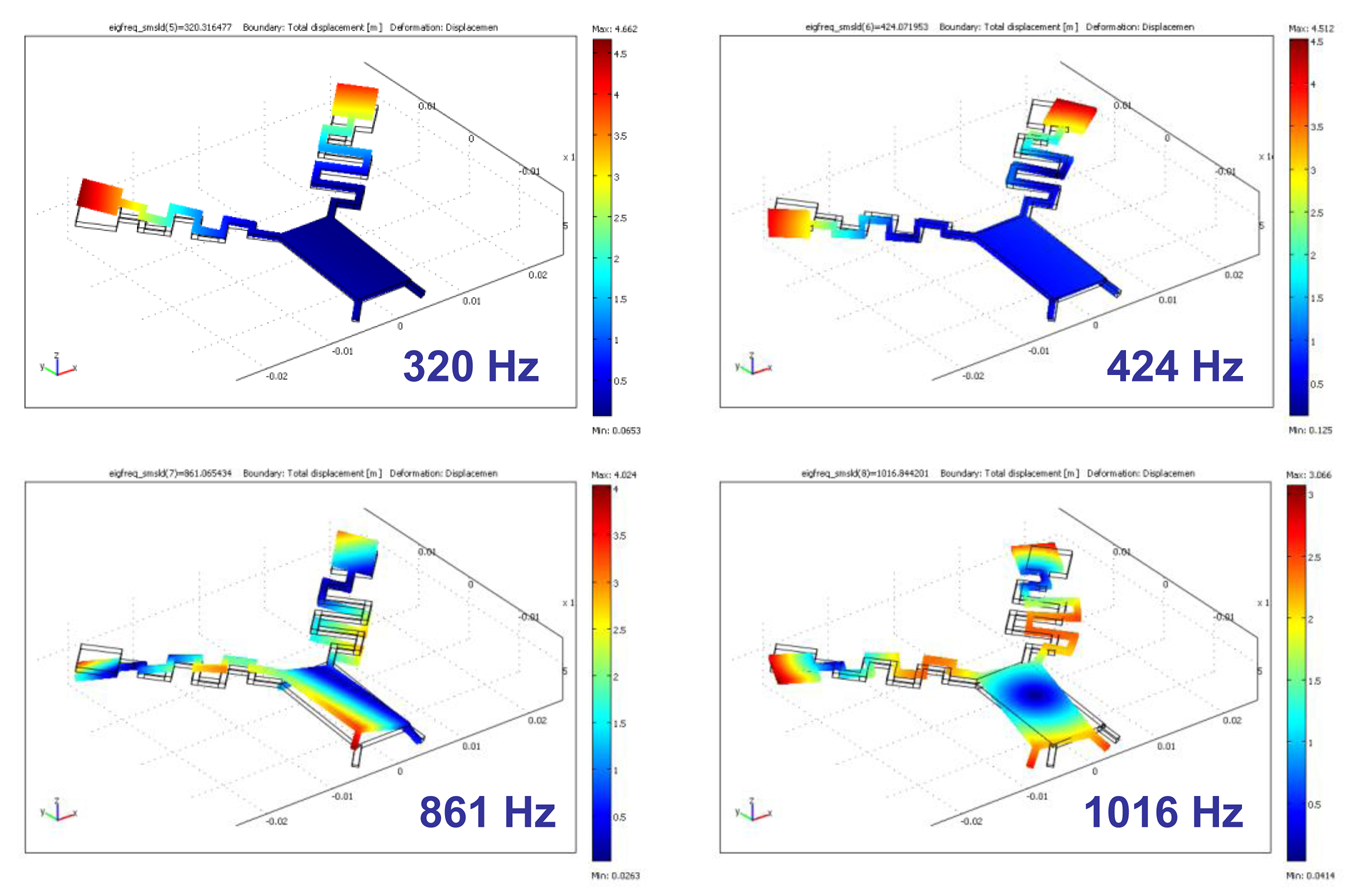
The jitterbot was modeled in 3D using the Solid Stress-Strain application module of COMSOL. In order to model the theoretical rocking behavior of the robot, the z-axis forcing oscillation was applied only to the front and right rear leg, while these legs were unconstrained in x and y. No other constraints were placed on the robot. These boundary conditions are illustrated in Figure 3. The predicted eigenfrequencies with these boundary conditions occur at 320 Hz, 424 Hz, 861 Hz, and 1,016 Hz. These eigenmodes are illustrated in Figure 4.
To see how these modes might contribute to translation, we also mapped how the mode affected the center of mass. In COMSOL, we used an adaptive mesh and set up integration coupling variables to integrate over the volume. Since this was done with the eigenmodes, the resulting amplitude values are arbitrary, but it was found that for the 320 Hz, 424 Hz, and 861 Hz modes, the center of mass shifts down and to the right—consistent with clockwise rotation, while for the 1,016 Hz eigenmodes, the center of mass shifts down and to the left, consistent with counterclockwise motion.
4. Test Procedure and Results
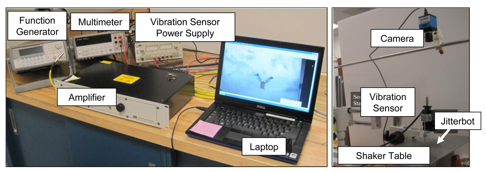
The robot was first observed using an Olympus I-Speed 2 high speed camera. The vibration frequency was scanned over the range of 10 to 2,000 Hz while the behavior of the robot was recorded. Studies were also conducted to quantify motion versus vibration amplitude and to investigate the dependence of the motion on the front leg angle. For these studies, the robot was observed with an Imaging Source USB camera, mounted with the optical axis of the lens perpendicular to the vibrating surface. In order to precisely measure the amplitude of the platform vibration, a Philtec Fiber Optic Sensor Model D125 was used which provided a voltage output that correlated to the distance between the sensor and the platform. Using this vibration sensor we observed that the shaker table amplitude varied significantly with position and frequency. The test setup is shown in Figure 5. The video was then analyzed in MATLAB for velocity and angular velocity. For the angle of attack studies, the front leg angle as illustrated in Figure 2, was adjusted for three different angles relative to the shaker table surface: 36°, 55°, and 76°.
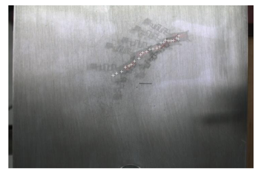
The robot was observed to rotate clockwise with varying degrees of translation at about 97, 236, 693 and 810 Hz, and to rotate counterclockwise with some translation at 1,090 Hz. Each of those modes was observed repeatedly, but with a deviation of ±10 Hz as testing conditions changed. Robot motion was less consistent at the lower resonance frequencies—often “jumping” or falling over on to the right hand, even at low vibration amplitudes. We termed this type of motion to be “popcorn”-like —interesting but not useful for robot locomotion. At the higher resonance frequencies, the motion was steady and reproducible. Overlapping still shots taken from the 810 and 1,090 Hz rotations are shown below in Figures 6 and 7. The 1,090 Hz motion was weaker than that at 810 Hz, requiring about twice the amount of vibration amplitude to produce a similar rate of turn. The preference for right-leaning and clockwise motion can be partially explained by the greater mass of the right arm. A close analysis of the high speed camera footage confirmed that the robot rocked as it moved. For both the clockwise and counter-clockwise turns it tends to rock off of the rear left leg (the leg opposite the more massive right arm). It rocks off this leg more often for the clockwise turns than for the counter-clockwise turns. These results were reasonably consistent with those of the COMSOL simulation, which is summarized in Table 1, particular in the case of the higher frequency eigenmodes. For the lower frequency eigenmodes, which display the “popcorn” behavior—the rocking boundary conditions set in the model are less accurate.
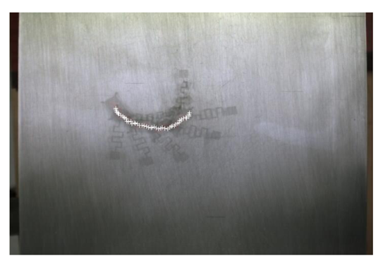
The 686 and 1,090 Hz modes were examined in more detail to determine how the robot's velocity and angular velocity depended on vibration amplitude. The overhead camera was used to record robot motion. Sample trajectories are shown in Figures 8 and 9.
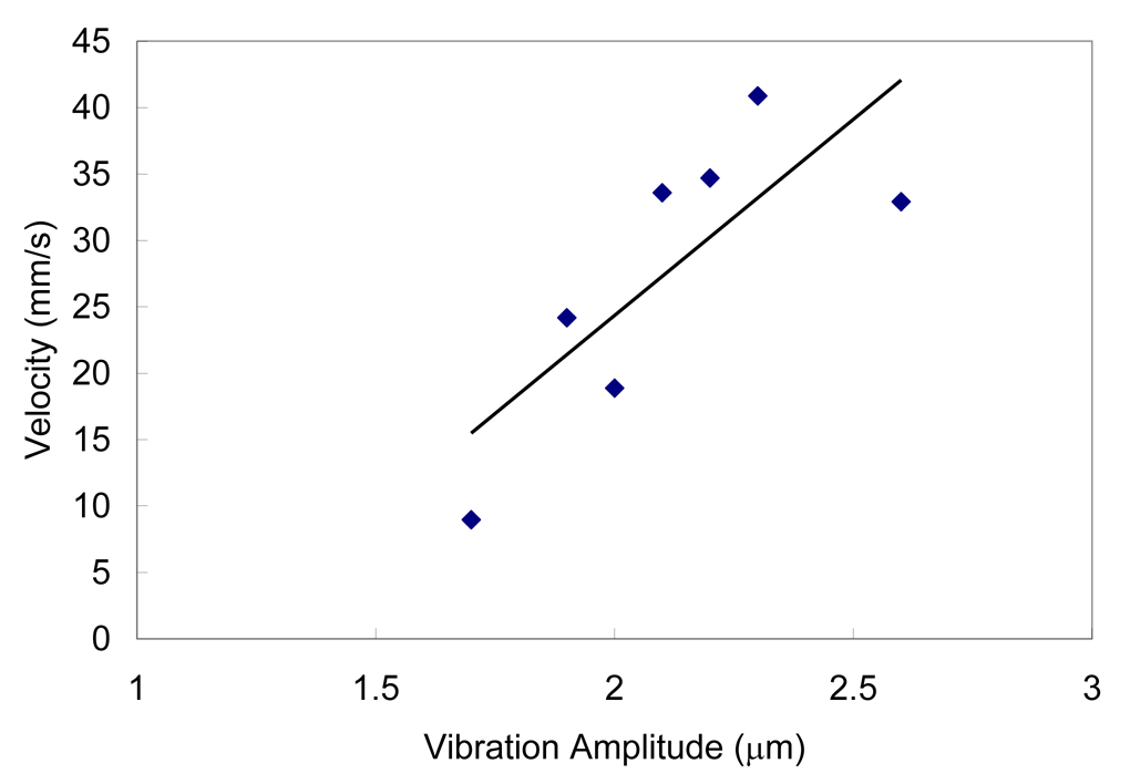
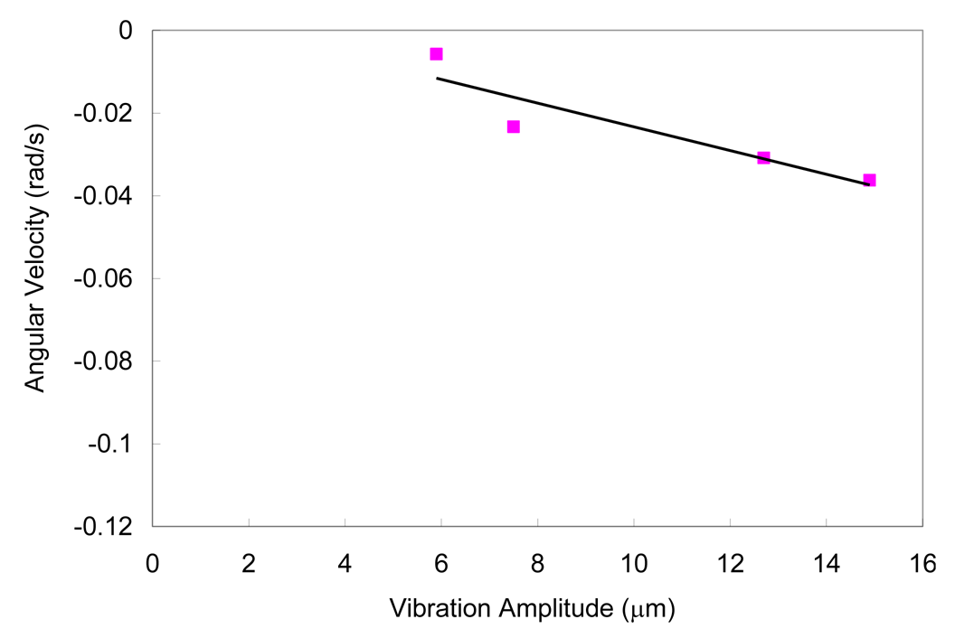
Velocity was determined in MATLAB by analyzing the position of the centroid in each frame and then multiplying the centroid travel distance between frames by the frame rate. Velocity units were converted from pixels per second to mm per second using pixel dimensions. The frame by frame results were then averaged over the data set. Rotational velocity was determined in a similar way by comparing blob orientation between frames. For these studies, the optical displacement sensor was used to calibrate the plate at the robot location for different signal generator amplitudes. The results are shown in Figures 10–13. There is a clear correlation between the vibration amplitude and the robot's velocity. The range for the shaker amplitude in this data is limited for two reasons: frequency variability in the shaker plate and the limited frame of the camera. The shaker plate amplitude was highly dependent on position and frequency, as well as on how the shaker plate was attached to the shaker and supported. For a given operation mode, there was a relatively narrow window of shaker plate displacements available that would also keep the robot within the reference frame of the camera for a reasonable length of time.
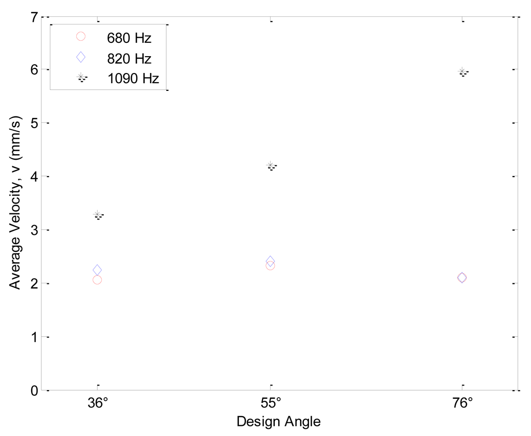
The results of the front leg angle study are shown in Figures 14 and 15. The shaker stage had been modified from the earlier studies, so that absolute stage displacement values were not known. For these studies the stage vibration amplitude was adjusted for each frequency mode to give a measurable but small response (so that the robot would not move too quickly out of the camera field of view), although the amplitude and starting stage location was kept constant for the same frequency across different angles. Altering the angle of the front leg had little effect on the resonant frequencies for the structure. It also did not affect the forward velocity or angular rate except in the case of the 1,090 Hz mode. For this mode, velocities increased with leg angle.
5. Downsizing to the Microscale
In summary, the experimental results demonstrate the viability of vibration actuation at the millimeter size scale. The front leg angle study data also suggests that increasing the front angle will increase robot speed in at least one of the frequency modes. This is useful as we consider the next design phase of bringing the device down to the microscale. A microscale version of this robot could be formed using a standard multi-user microfabrication process followed by the post-process addition of a stress layer on the legs, in a manner similar to the fabrication of other microrobots [3]. Varying angles could be achieved by altering the fractional coverage of the stress-inducing layer on the legs. COMSOL was used to model determine the operational frequencies were all dimensions reduced by a factors of 100 and of 1,000, and the material changed to polysilicon. The resulting eigenfrequencies were in the 50 kHz to 2 MHz range, which includes frequencies already in use in medical ultrasonic equipment. However, there are significant challenges with the reduction to microscale that were not captured by this COMSOL model—in particular surface tension forces are not well understood at these size scales, and they will dominate robot behavior as the size and mass reduces. Rather than a completely proportional scaling, the authors will explore making use of multiple layers within the fabrication process to keep the body and hands relatively thick compared to the hands and arms as the device reduces in dimension.
6. Conclusions
This work demonstrates a meso-scale seismically actuated robot that can be steered by controlling the frequency of the global vibration field. Furthermore, our experimental results are consistent with finite element modeling predictions, particularly for the higher frequency rocking modes. With the two motion primitives of turning clockwise with translation and counter-clockwise with translation, the Jitterbot can theoretically be moved to any arbitrary point by altering the frequency of the vibration field. The device design is also compatible with scaling down to the microscale using a standard microfabrication process, however there will be additional technical hurdles in this miniaturization as inertial forces decrease with respect to friction forces.
An additional avenue of exploration for future work would be to study how different operational media, such as water or oil, might affect operation. Also, the ability of jitterbots to interact with other objects should be investigated, in order to assess the potential of these robots for micromanipulation tasks. Finally, the authors plan to investigate how the motion primitives can be combined to steer the robot in an arbitrary path. This task would be simplified if the device could be modified to achieve a purely translational (without rotation) motion primitive, which could be achieved by rearranging the suspended springs in the device.


| Experimental | COMSOL |
|---|---|
| 90–100 Hz (CW) | |
| 220–240 Hz (CW) | 320 Hz (CW) |
| 680–690 Hz (CW) | 424 Hz (CW) |
| 810–820 Hz (CW) | 861 Hz (CW) |
| 1,085–1,095 Hz (CCW) | 1,016 Hz (CCW) |
Acknowledgments
This work began as an undergraduate research project sponsored by the Department of the Navy's Program Executive Office for Integrated Warfare Systems (PEO/IWS). The authors also wish to thank the USNA machine shop, particularly Matt Stanley, for the machining of the jitterbots. The authors also wish to thank Anders Ekerot at COMSOL for his assistance in setting up the ALE application mode for the finite element model.
References
- Abbott, J.; Nagy, Z.; Beyeler, F.; Nelson, B. Robotics in the small. IEEE Robot. Autom. Mag. 2007, 14, 92–103. [Google Scholar]
- Firebaugh, S.L.; Piepmeier, J.A.; McGray, C.D. Soccer at the microscale: Small robots with big impact. In Robot Soccer; Papic, V., Ed.; In-Tech: Vukovar, Croatia, 2010. [Google Scholar]
- Donald, B.; Levey, C.; McGray, C.; Rus, D.; Sinclair, M. Power delivery and locomotion of untethered microactuators. J. Microelectromech. Syst. 2003, 12, 947–959. [Google Scholar]
- Vollmers, K.; Frutiger, D.; Kratochvil, B.; Nelson, B. Wireless resonant magnetic microactuator for untethered mobile microrobots. Appl. Phys. Lett. 2008, 92, 144103. [Google Scholar]
- Pawashe, C.; Floyd, S.; Sitti, M. Modeling and experimental characterization of an untethered magnetic micro-robot. Int. J. Robot. Res. 2009, 28, 1077–1094. [Google Scholar]
- Yasuda, T.; Shimoyama, I.; Miura, H. Microrobot actuated by a vibration energy field. Sens. Actuat. 1994, 43, 366–370. [Google Scholar]
- Yasuda, T.; Shimoyama, I.; Miura, H. Microrobot locomotion in a mechanical vibration field. Adv. Robot. 1995, 9, 165–176. [Google Scholar]
- Saitou, K.; Wang, D.-A.; Wou, S.J. Externally resonated linear microvibromotor for microassembly. J. Microelectromech. Syst. 2000, 9, 336. [Google Scholar]
- Mathieu, J.-B.; Beaudoin, G.; Martel, S. Method of propulsion of a ferromagnetic core in the cardiovascular system through magnetic gradients generated by an MRI system. IEEE Trans. Biomed. Eng. 2006, 53, 292–299. [Google Scholar]
- Sul, O.J.; Falvo, M.R.; Taylor, R.M.; Washburn, S., II.; Superfine, R. Thermally actuated untethered impact-driven locomotive microdevices. Appl. Phys. Lett. 2006, 89, 203512. [Google Scholar]
© 2011 by the authors; licensee MDPI, Basel, Switzerland. This article is an open access article distributed under the terms and conditions of the Creative Commons Attribution license (http://creativecommons.org/licenses/by/3.0/).
Share and Cite
Firebaugh, S.; Piepmeier, J.; Leckie, E.; Burkhardt, J. Jitterbot: A Mobile Millirobot Using Vibration Actuation. Micromachines 2011, 2, 295-305. https://doi.org/10.3390/mi2020295
Firebaugh S, Piepmeier J, Leckie E, Burkhardt J. Jitterbot: A Mobile Millirobot Using Vibration Actuation. Micromachines. 2011; 2(2):295-305. https://doi.org/10.3390/mi2020295
Chicago/Turabian StyleFirebaugh, Samara, Jenelle Piepmeier, Elizabeth Leckie, and John Burkhardt. 2011. "Jitterbot: A Mobile Millirobot Using Vibration Actuation" Micromachines 2, no. 2: 295-305. https://doi.org/10.3390/mi2020295