Cylindrical Resonator Utilizing a Curved Resonant Grating as a Cavity Wall

Abstract
:1. Introduction

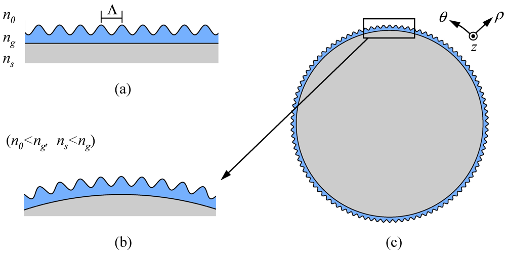
2. Characteristics of a Curved RG
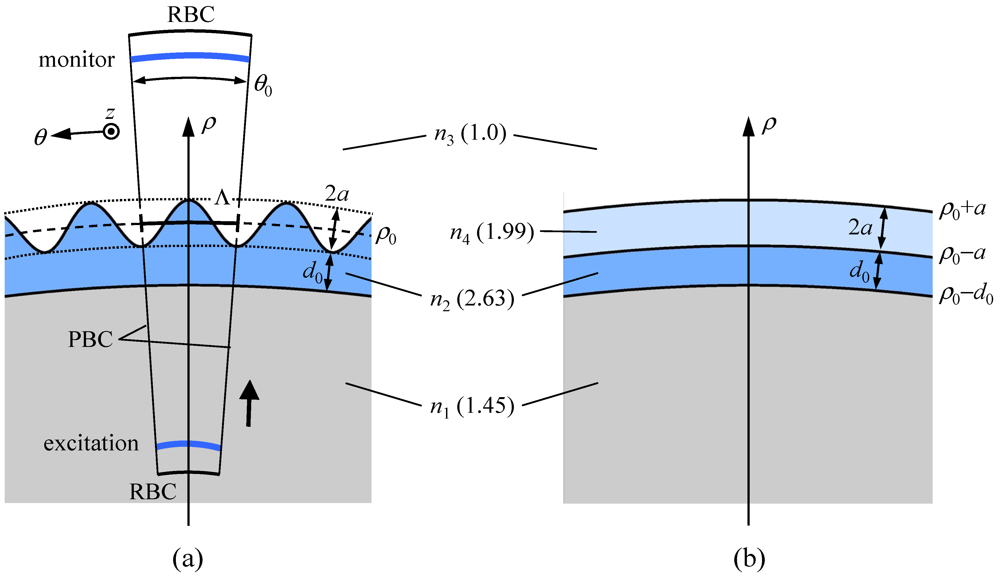
2.1. Structure and Method of Calculation

 (1)
(1)  .
.
 (2)
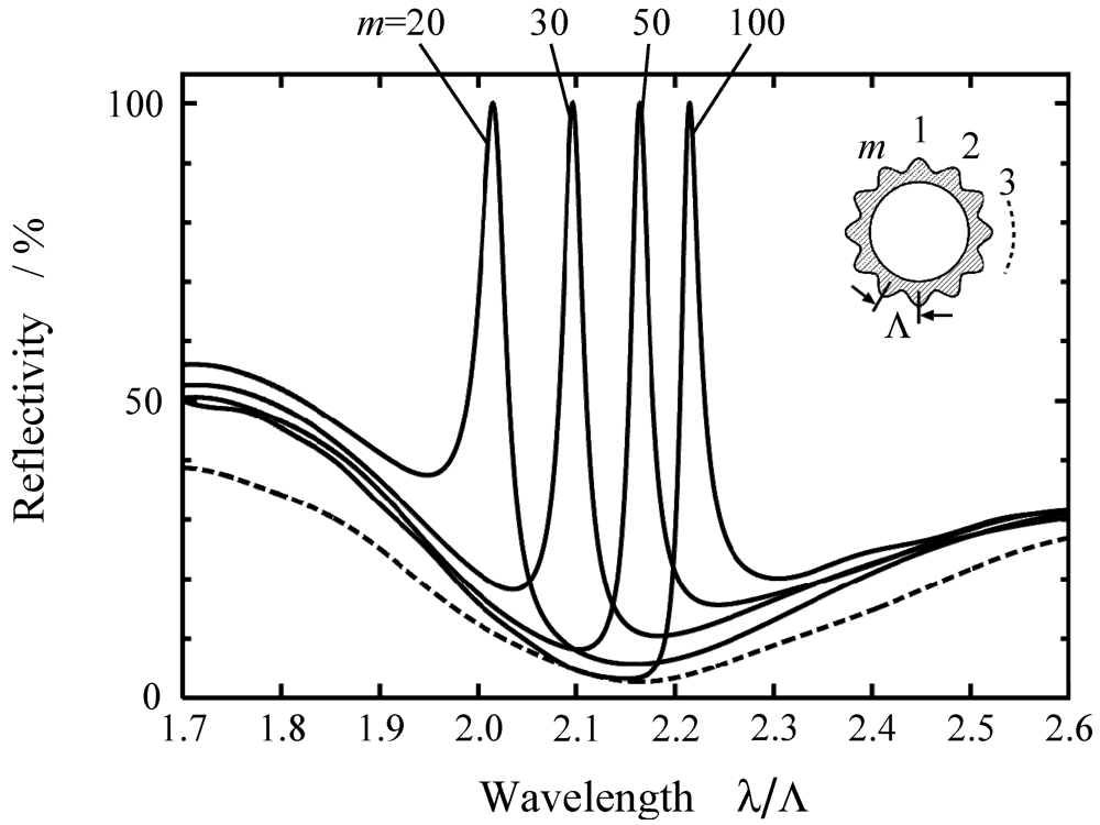
(2) 2.2. Reflection Spectra
 . A similar calculation is carried out for a uniform space of n = 1.45 to obtain a reference Poynting vector
  . The reflectivity of RG is then evaluated by
  . The results for various curvature radii are plotted in Figure 3. It is clearly seen that the spectra are the superposition of average structure reflectivity (Figure 2(b)) and a sharp resonance peak.
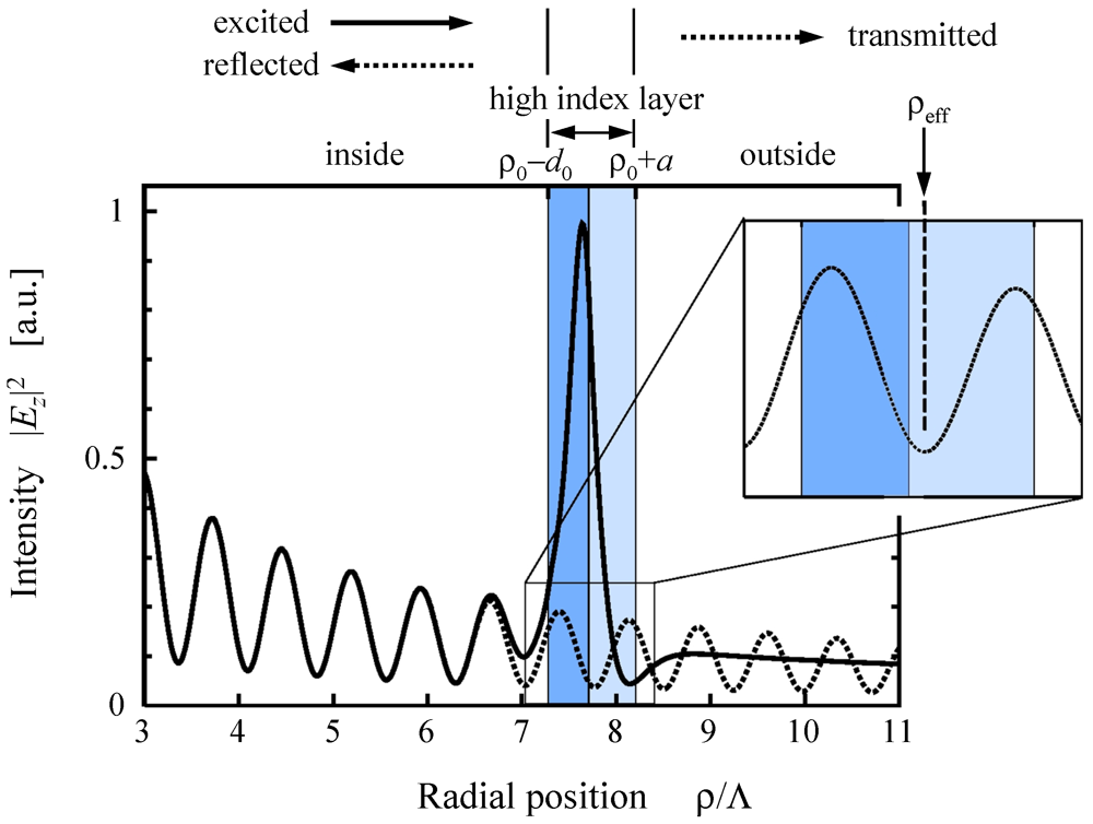
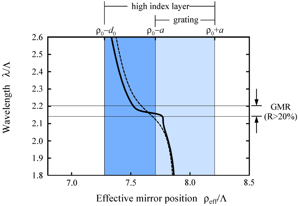
2.3. Effective High-Index Mirror Position

 (3)
(3)  and
and  denote the 0th-order Hankel function of the first and second kind, and correspond to converging and diverging waves, respectively. Ac and Ad are their complex amplitudes. k0 and ρ are the free space wave number and the radial coordinate, respectively.
 should therefore be a negative real number. The electric field at such a plane can thus be expressed as:
 (4)
(4)  (5)
(5)  ,
,  (6)
(6)  and
and  .
and .
.
and .

3. Characteristics of RGC
3.1. Resonance Wavelength of the Cavity Mode
 , where ρeff is the radial position of the effective high-index mirror.
, where ρeff is the radial position of the effective high-index mirror.
, where ρeff is the radial position of the effective high-index mirror.
 (7)
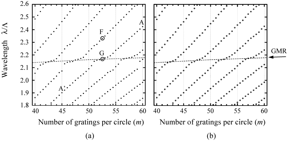
(7)  is the radius of the cavity. We tried to check whether or not this condition also applies to our RG-type resonator. We replaced the physical radius ( ) by the effective one (
  ) and plotted the wavelengths which satisfy the above relationship for various cavity sizes (m). The effective position, , for various curvatures was calculated by the procedure described in Section 2.3. The result is shown in Figure 7(b). These results look similar for both Fresnel and Grating modes. It is clear that the deformation of the resonance curve near the GMR wavelength corresponds to the behavior of seen in Figure 6. This indicates that the resonance wavelength of the proposed cavity is also governed by the conventional resonance condition of Equation (7), regardless of the confinement mechanism (Fresnel reflection or resonant reflection) of the modes.
3.2. Quality Factor
 (8)
(8) 

4. Conclusions
Acknowledgment
References
- Collin, R.E. Electromagnetic Resonators. In Foundations for Microwave Engineering, 2nd ed; Wiley: Hoboken, NJ, USA, 2001; pp. 496–517. [Google Scholar]
- Cohn, S.B. Microwave bandpass filters containing high-Q dielectric resonators. IEEE Trans. Microw. Theory Tech. 1968, MTT-16, 218–227. [Google Scholar] [CrossRef]
- Jiao, X.H.; Cuillon, P.; Bermudez, L.A.; Auxemery, P. Whispering-Gallery modes of dielectric structures: Applications to millimeter-wave bandstop filters. IEEE Trans. Microw. Theory Tech. 1987, MTT-35, 1169–1175. [Google Scholar]
- Cros, D.; Guillon, P. Whispering Gallery dielectric resonator modes for W-band devices. IEEE Trans. Microw. Theory Tech. 1990, 38, 1667–1674. [Google Scholar] [CrossRef]
- Preu, S.; Schwefel, H.G.L.; Malzer, S.; Dohler, G.H.; Wang, L.J.; Hanson, M.; Zimmerman, J.D.; Gossard, A.C. Coupled whispering gallery mode resonators in Terahertz frequency range. Opt. Express 2008, 16, 7336–7343. [Google Scholar]
- Alexopoulos, N.G.; Kerner, S. Coupled power theorem and orthogonality relations for optical disk waveguides. J. Opt. Soc. Am. 1977, 67, 1634–1638. [Google Scholar] [CrossRef]
- Vahala, K.J. Optical microcavities. Nature 2003, 424, 839–846. [Google Scholar] [CrossRef]
- Ilchenko, V.S.; Matsko, A.B. Optical resonators with whispering-gallery modes-part II: Applications. IEEE J. Sel. Top. Quantum Electron. 2006, 12, 15–32. [Google Scholar] [CrossRef]
- Scheuer, J.; Yariv, A. Annular Bragg defect mode resonators. J. Opt. Soc. Am. B 2003, 20, 2285–2291. [Google Scholar] [CrossRef]
- Sun, X.; Yariv, A. Surface-emitting circular DFB, disk-, and ring-Bragg resonator laser with chirped gratings: A unified theory and comparative study. Opt. Express 2008, 16, 9155–9164. [Google Scholar] [CrossRef]
- Fujita, M.; Baba, T. Microgear laser. Appl. Phys. Lett. 2002, 80, 2051–2053. [Google Scholar] [CrossRef]
- Wang, S.S.; Magnusson, R.; Bagby, J.S.; Moharam, M.G. Guided-mode resonances in planar dielectric-layer diffraction gratings. J. Opt. Soc. Am. A 1990, 7, 1470–1474. [Google Scholar] [CrossRef]
- Wang, S.S.; Magnusson, R. Theory and applications of guided-mode resonance filters. Appl. Opt. 1993, 32, 2606–2613. [Google Scholar] [CrossRef]
- Vincent, P.; Neviere, M. Corrugated dielectric waveguides: A numerical study of the second-order stop bands. Appl. Phys. 1979, 20, 345–351. [Google Scholar] [CrossRef]
- Rosenblatt, D.; Sharon, A.; Friesem, A.A. Resonant grating waveguide structures. IEEE J. Quantum Electron. 1997, 33, 2038–2059. [Google Scholar] [CrossRef]
- Peters, D.W.; Kemme, S.A.; Hadley, G.R. Effect of finite grating, waveguide width, and end-facet geometry on resonant subwavelength grating reflectivity. J. Opt. Soc. Am. A 2004, 21, 981–987. [Google Scholar] [CrossRef]
- Peters, D.W.; Boye, R.R.; Wendt, J.R.; Kellogg, R.A.; Kemme, S.A.; Carter, T.R.; Samora, S. Demonstration of polarization-independent resonant subwavelength grating filter arrays. Opt. Lett. 2010, 35, 3201–3203. [Google Scholar]
- Ding, Y.; Magnusson, R. Resonant leaky-mode spectral-band engineering and device applications. Opt. Express 2004, 12, 5661–5674. [Google Scholar] [CrossRef]
- Liu, Z.S.; Tibuleac, S.; Shin, D.; Young, P.P.; Magnusson, R. High-efficiency guided-mode resonance filter. Opt. Lett. 1998, 23, 1556–1558. [Google Scholar] [CrossRef]
- Fattal, D.; Li, J.; Peng, Z.; Fiorentino, M.; Beausoleil, R.G. Flat dielectric grating reflectors with focusing abilities. Nature Photon. 2010, 4, 466–470. [Google Scholar] [CrossRef]
- Ohtera, Y.; Iijima, S.; Yamada, H. Guided-mode resonance in curved grating structures. Opt. Lett. 2011, 36, 1689–1691. [Google Scholar] [CrossRef]
- Lu, M.; Zhai, H.; Magnusson, R. Focusing light with curved guided-mode resonance reflectors. Micromachines 2011, 2, 150–156. [Google Scholar] [CrossRef]
- Hocker, G.B.; Burns, W.K. Mode dispersion in diffused channel waveguides by the effective index method. Appl. Opt. 1977, 16, 113–118. [Google Scholar] [CrossRef]
- Huy, K.P.; Morand, A.; Amans, D.; Benech, P. Analytical study of the whispering-gallery mode in two-dimensional microgear cavity using coupled-mode theory. J. Opt. Soc. Am. B 2005, 22, 1793–1803. [Google Scholar] [CrossRef]
- Taflove, A. Computational Electrodynamics: The Finite-Difference Time-Domain Method; Artech House: Boston, MA, USA, 1995; pp. 397–410. [Google Scholar]
- Xu, Y.; Vuckovic, J.S.; Lee, R.K.; Painter, O.J.; Scherer, A.; Yariv, A. Finite-difference time-domain calculation of spontaneous emission lifetime in a microcavity. J. Opt. Soc. Am. B 1999, 16, 465–474. [Google Scholar] [CrossRef]
- Gambling, W.A.; Matsumura, H.; Ragdale, C.M. Field deformation in a curved single-mode fibre. Electron. Lett. 1978, 14, 130–132. [Google Scholar]
- Fan, S.; Joannopoulos, J.D. Analysis of guided resonances in photonic crystal slabs. Phys. Rev. B 2002, 65, 235112:1–235112:8. [Google Scholar]
- Pozer, D.M. Microwave Engineering, 3rd ed; Wiley: Hoboken, NJ, USA, 2005; pp. 117–126. [Google Scholar]
- Haus, H.A. Waves and Fields in Optoelectronics; Prentice-Hall: Upper Saddle River, NJ, USA, 1984; p. 208. [Google Scholar]
- Magnusson, R.; S-Saremi, M. Widely tunable guided-mode resonance nanoelectromechanical RGB pixels. Opt. Express 2007, 15, 10903–10910. [Google Scholar] [CrossRef]
© 2012 by the authors; licensee MDPI, Basel, Switzerland. This article is an open-access article distributed under the terms and conditions of the Creative Commons Attribution license (http://creativecommons.org/licenses/by/3.0/).
Share and Cite
Ohtera, Y.; Iijima, S.; Yamada, H. Cylindrical Resonator Utilizing a Curved Resonant Grating as a Cavity Wall. Micromachines 2012, 3, 101-113. https://doi.org/10.3390/mi3010101
Ohtera Y, Iijima S, Yamada H. Cylindrical Resonator Utilizing a Curved Resonant Grating as a Cavity Wall. Micromachines. 2012; 3(1):101-113. https://doi.org/10.3390/mi3010101
Chicago/Turabian StyleOhtera, Yasuo, Shohei Iijima, and Hirohito Yamada. 2012. "Cylindrical Resonator Utilizing a Curved Resonant Grating as a Cavity Wall" Micromachines 3, no. 1: 101-113. https://doi.org/10.3390/mi3010101