A Digitally Controllable Polymer-Based Microfluidic Mixing Module Array


Department of Mechanical and Biomedical Engineering, City University of Hong Kong, Kowloon, Hong Kong, China
*
Authors to whom correspondence should be addressed.
Micromachines 2012, 3(2), 279-294; https://doi.org/10.3390/mi3020279
Submission received: 11 February 2012
/
Revised: 15 March 2012
/
Accepted: 27 March 2012
/
Published: 29 March 2012
(This article belongs to the Special Issue Micro Flow Controllers)
Abstract
:This paper presents an integrated digitally controllable microfluidic system for continuous solution supply with a real-time concentration control. This system contains multiple independently operating mixing modules, each integrated with two vortex micropumps, two Tesla valves and a micromixer. The interior surface of the system is made of biocompatible materials using a polymer micro-fabrication process and thus its operation can be applied to chemicals and bio-reagents. In each module, pumping of fluid is achieved by the vortex micropump working with the rotation of a micro-impeller. The downstream fluid mixing is based on mechanical vibrations driven by a lead zirconate titanate ceramic diaphragm actuator located below the mixing chamber. We have conducted experiments to prove that the addition of the micro-pillar structures to the mixing chamber further improves the mixing performance. We also developed a computer-controlled automated driver system to control the real-time fluid mixing and concentration regulation with the mixing module array. This research demonstrates the integration of digitally controllable polymer-based microfluidic modules as a fully functional system, which has great potential in the automation of many bio-fluid handling processes in bio-related applications.
1. Introduction
Research on microfluidics has been advancing rapidly in the past two decades—progressing from single channel devices [1] to complicated and multifunctional systems integrating manifold microfluidic components [2,3,4]. With the advancement of polymer-based microfabrication technology [5], contemporary microfluidics is no longer restricted to silicon-based devices and can be biocompatible. Various microfluidic devices, such as micropump [6,7], microvalve [8,9], micromixer [10,11] and microfluidic flow sensors [12,13,14] were developed with more robust functionalities. Integrated microfluidic systems, which are composed of multiple microfluidic components, have been typically applied to manipulate, regenerate and sense chemicals and bio-fluids with volumes ranging from micro-liters down to pico-liters [15,16,17,18,19] for delicate and sensitive biochemical applications, e.g., single-cell [20], subcellular [21] and single-molecule [22] analyses. While microfluidics has achieved superior processing, the detection of biochemical samples, preparation and handling of a large variety of samples with defined concentrations are also indispensable demands for the automation of these highly integrated miniaturized systems.
In addition, development of integrated microfluidic systems includes long-term operation and high-throughput applications. [23,24,25] An analysis of an individual region in the system may consume only pico-liters of chemicals/bio-reagents, yet the total required volume for multiple regions can accumulate up to micro/submicro-liters. The current liquid preparation processes often rely on manual pipetting with a low yield and consistency, or on bulky macro-scale automated machines incompatible with the integrated microfluidic systems. These limitations have been critical challenges for practical biomedical and clinical implementations. Therefore, portable and digitally controllable micro-machines with precise concentration controls should be developed as the interface between the stock biochemical solutions and the automated microfluidic processes.
A microfluidic pump is an actuator that provides hydraulic pressure and volumetric flow to displace liquids along channels in microfluidic systems. Major concerns in the device development are size, driving power, flow rate and induced hydraulic pressure. Some of the typical embedded micropumps (e.g., peristaltic [8] and electrokinetic [26] micropumps) may be challenged to achieve the relatively fast micro-flow (~0.1–10 mL/min) to drive biochemical samples for high-throughput microfluidic operations. Instead, conventional continuous-flow micropumps such as lead zirconate titanate (PZT) valveless micropumps [27,28] can fulfill such flow requirement, as it has been reported that this type of microdevice attaines flow rates up to 0.5 mL/min and works against a back pressure of >102 kPa [28].
Moreover, mixing of multiple liquids is required in many microfluidic systems handling liquids, typically with a low Reynolds number laminar flow, in which molecular transport is mainly due to diffusion. The mixing enhancement can be achieved by (1) a passive geometry design of microchannels and (2) the application of external actuation energy to actively generate molecular vibration in liquids [29]. Over the years, many micro-mixing devices have been described based on distinct principles, for example, parallel lamination [30], mechanical vibration [27], Taylor dispersion [31,32] and electrokinetic pumping [33]. Among various approaches, the active mechanical vibration mixing mechanism could support superior mixing efficiency for a continuous liquid stream with high flow rate and a wide range of Reynolds numbers for sample preparation applications [27,34].
Here, we present a digitally controllable polymer-based microfluidic system integrated with vortex micropumps and vibration-based micromixers for thorough mixing and delivery of continuously flowing liquids with flow rates of ~0.1–10 mL/min. Multiple independently operating modules were designed and characterized in our system for parallel liquid preparation with adjustable concentrations. This microfluidic system is a requisite to deliver fluid with adjustable sequence, fast mixing with the desired mixing ratio and, hence, to miniaturize the bio-fluid and chemical preparation processes. Furthermore, a portable computer-controlled driver system has also been developed for real-time control of the microfluidic components. Integrating the control system with the microfluidic systems can potentially achieve fast and precise microfluidic processes and automate bio-fluid manipulation, mixing and detection.
2. Methods
2.1. Fabrication
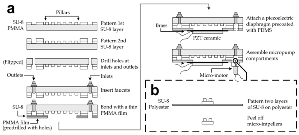
The fabrication of the microfluidic mixing module array is illustrated in Figure 1(a). Two layers of ~100 µm height channel patterns on a polymethylmethacrylate (PMMA) substrate (thickness: 3 mm) were manufactured by photolithography of SU-8 (SU-8 100, Microchem, Newton, MA, USA). The structural materials were chosen due to their biocompatibility and optical transparency. The first layer of SU-8 was spincoated on the PMMA substrate, baked at 50 °C for 5 min and 70 °C for 40 min, exposed to ultraviolet (UV) radiation with the patterns of micro-pillars and fluidic connections (energy: 1 mW/cm2 for 120 s), and post-exposure baked at 50 °C for 30 min. The second SU-8 layer containing microchannel and mixing chamber (diameter: 11 mm) patterns was aligned and fabricated with the same photolithography procedures, followed by developing with the SU-8 developer (Microchem) for 10 min. The substrate was then briefly rinsed with isopropyl alcohol and distilled water. The device inlets and outlets were generated by drilling holes with diameter of 2.9 mm to allow the insertion of faucets. Afterwards, another thin PMMA film (thickness: 500 µm) with predrilled holes at fluidic connections and chamber openings (diameter: ~10 mm) was bonded to the pattern side of the PMMA-SU-8 substrate using a layer of uncured SU-8 (SU-8 5, Microchem), which had been pre-spincoated on the PMMA film at 4,000 rpm for 40 s. The permanent sealing formed by UV-exposure (energy: >200 mJ/cm2) and baking at 50 °C for >120 min achieved closed channels between the the PMMA substrate and the film. Furthermore, brass diaphragms (diameter: 11 mm) each pre-deposited with an underlying lead zirconate titanate (PZT) ceramic film (diameter: 9 mm, resonant frequency: ~1.5 kHz; South China Electronics, Hong Kong) were spincoated (~4,000 rpm for 60 s) on their brass side with a layer of ~10 μm thick polydimethylsiloxane (PDMS; Sylgard 184, Dow Corning Corporation, Midland, MI, USA) to achieve surface biocompatibility. The outer region of the PDMS layer was then cut and peeled off from each brass diaphragm and replaced by uncured SU-8 (SU-8 5, Microchem) as an adhesive to bond the diaphragm to each mixing chamber region. The lower sides of brass and PZT ceramic were soldered with electrical wires for electrical connection of the oscillating driving voltage. Because the piezoelectric PZT layer was attached under each diaphragm, liquids in the mixing chambers could be mechanically oscillated under the driving voltage. The height of the chamber wall was 100 µm taller than that of the pillars, so the diaphragm could vibrate freely given the vertical displacement was limited to <100 µm.
Figure 1.
Fabrication processes of (a) the microfluidic mixing module array and (b) the micro impellers.
Figure 1.
Fabrication processes of (a) the microfluidic mixing module array and (b) the micro impellers.

On the other hand, the micropump compartments were each equipped with a motor, and an SU-8 impeller and a PMMA substrate containing a micropump cavity. Fabrication of the biocompatible impellers based on photolithography of SU-8 is shown in Figure 1b. The circular bases of the impellers (diameter: 3 mm) were patterned by the photolithography of SU-8 (SU-8 100) for a thickness of 100 μm on a polyester film; then the 100 μm tall blade patterns were aligned and patterned again by the photolithography of SU-8 (SU-8 100). Release of the SU-8 impellers was simply achieved by peeling off manually. Each individual impeller was then fixed using SU-8 (SU-8 5) with baking and UV-exposure on the shaft of a micro-motor (Jinlong Technology, Hong Kong) mounted in each micropump cavity, which had been created by drilling with a diameter of 4 mm and to a depth of ~1 mm. Afterwards each micropump compartment was bonded to the cavity below each inlet using SU-8 (SU-8 5). Finally, the corners of the mixing module array were drilled with holes for the insertion of the device stands.
2.2. Actuation of Micropumps and Micromixers
An electrical manifold device driver was created to generate electrical driving signals for both the micropump and micromixer units of the microfluidic mixing module arrays. (Details of the electronic circuit are discussed in the Appendix.) Briefly, relay-based switches were applied to control the activation of the micromixers individually. The driver generated square-wave signals to actuate active acoustic mechanical vibration (~1–3 kHz) of the piezoelectric diaphragms below the mixing chambers for mixing enhancement. On the other hand, the vortex micropump units were actuated by a steady voltage from either a commercial power supply or our manifold device driver.
2.3. Measurement of Micropump Characteristics
We calibrated the impeller rotational speed in the micropump chamber driven by different input voltages based on an optical measurement strategy. Technically, a light beam windowed from a light emitting diode using a film mask with an aperture was illuminated from the topside of the micropump region, while a photodiode was mounted below the device for detection. In our measurement, one half of the impeller was pre-painted with black color to block the light beam, and thereby the impeller rotational speed could be reflected by the pulse signal frequency from the photodiode during pumping. To determine the micropump flow rate driven by a given voltage, the inlet and outlet of a micropump were each connected to a water reservoir. Water levels in the reservoirs were regulated to the same level prior to the experiments in order to eliminate the initial flow governed by gravity. The micropump then pumped water to the outlet with different driving voltages. In this stage, the change in liquid levels by micropumping was negligible. Hence, the pump discharge Q was measured from the weight increment at the outlet reservoir m with the relation Q = m/(ρt), where ρ is the liquid density and t is the pumping duration. To measure the induced hydraulic pressure, the pump outlet was connected to a vertical polyurethane tube for the liquid level measurement. The induced hydraulic pressure was indicated by the elevation of outlet liquid level during the operation of a vortex micropump driven by different input voltages. Similar to the flow rate characterization, the change of inlet liquid level was negligible and thus the pumping pressure P was estimated to be P = ρgh, where g is the gravitational acceleration and h is the liquid level elevation at the micropump outlet.
3. Results and Discussion
3.1. Design of Microfluidic Mixing Module Array
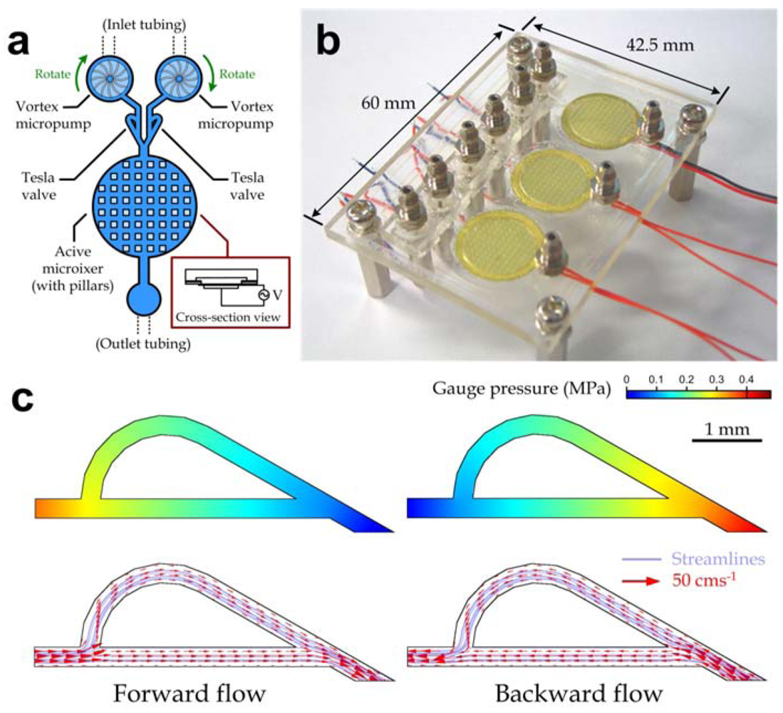
An array of digitally controllable mixing modules was developed to deliver multiple liquids with defined concentrations such as chemicals and bio-fluids. Because microfluidic devices are required to be transparent and chemically inert for many bio-optical detection applications, we chose PMMA as the major structural material. Multiple mixing modules, which each contained two vortex micropumps, two Tesla valves [35,36] and an active micromixer (Figure 2(a)), were fabricated in a single microfluidic device using our process described in Methods; and a fabricated microfluidic device (top view dimensions: 42.5 mm × 60 mm) integrated with three mixing modules is shown in Figure 2(b). Each module was utilized to supply a chemical or reagent with a regulated concentration of the additive components. This operation was achieved by delivering a stock solution with saturated concentration into one inlet using the vertex micropump, while another inlet was filled with distilled water that was pumped into it to dilute the stock solution to the required concentration. By replacing the distilled water with a solution containing additive components, the mixing module array can also be applied to solutions with variable concentrations of additive components. Furthermore, we developed a handheld automated driver system with both specialized hardware and software to control the integrated microfluidic device. (The system design and structure are available in the Appendix.) The driver system generated required electrical signals to actuate both the vortex micropumps and the active micromixers. Because such system replaced the required bulky macro-equipment, the overall automated concentration regulation implemented by our mixing module array was highly portable.
Figure 2.
Array of digitally controllable microfluidic mixing modules. (a) Device layout of a microfluidic mixing module; (b) Photograph of a fabricated device composed of three mixing modules; (c) Simulated pressure (top row) and velocity (bottom row) profiles of a Tesla valve model for the forward (left) and backward (right) flow directions.

The vortex micropump unit supported microfluidic applications that require liquid delivery in the micro-liter range. Its operation principle was based on the kinetic energy generated by the impeller rotation [37]. Fluidic pressure induced by centrifugal force at the center of impeller during rotation drove liquids to flow from the center to perimeter of the impeller. Consequently, the solution dilution or the additive component concentration was regulated by the ratio between the flow rates driven by the two inlet micropumps. The liquids from both inlets then passed the Tesla valves and merged at the “Y”-shape channel section indicated in Figure 2(a) and flowed into the micromixer chamber. Each of the active micromixer units was driven by an oscillating input voltage to actuate the diaphragm vibration perpendicular to the flow direction (inset in Figure 2(a)). It had been demonstrated that such mechanical vibration with a frequency in the range of ~1–10 kHz could induce a highly unsteady flow and enhance chaotic mixing [27]. The liquid mixture with a precisely defined concentration ratio of the two inlet liquids was then collected from the device outlet.
It should be mentioned that the Tesla microvalves (Figure 2(c)) located at the channel sections between the pumps and the mixers were applied to reduce potential backward flow since the backward fluidic resistance of the Tesla valve was comparatively higher than the forward one [36]. We performed computational analysis on the fluid flow in a Tesla valve to verify the flow resistance in different flow directions using commercially available software (COMSOL Multiphysics, COMSOL, Burlington, MA, USA). The average inflow velocity, 0.1667 ms−1 (equivalent to ~0.6 mL/min for our valve dimensions), of water flow was set at the Tesla microvalve model inlet/outlet for both forward and backward flow cases. Indeed, the simulation results validated that the fluidic pressure drop for backward flow (440.9 kPa) was larger than for forward flow (383 kPa). In our mixing module array, the Tesla valves were particularly effective to eliminate the net backward flow generated from the fluidic oscillation during the active mechanical mixing.
3.2. Pumping Characterization
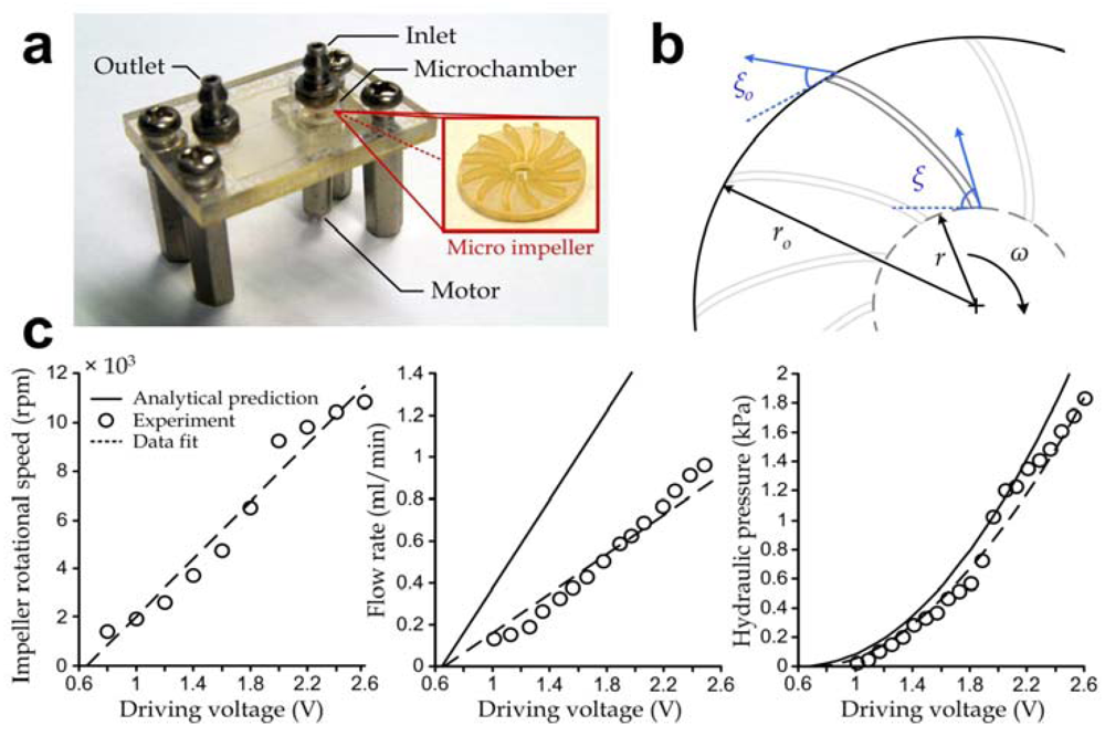
Structure and operation principle of the vortex micropump are similar to the classical centrifugal pump. Each device consists of a rotary impeller (outer diameter: 4.5 mm) located in a flow chamber (diameter: 5 mm), which is driven by the rotation of a mini-motor. To effectively characterize the micropump units, we fabricated the individual pump modules (Figure 2(a)) and performed experiments to investigate their operation performance in terms of the induced fluidic pressure and discharge. The experimental procedures are described in Methods. Fabrication of the micropumps was identical to the mixing module arrays, except that the assembly process of the piezoelectric diaphragm was omitted. During pumping, liquid entered from the center and was then pumped to the perimeter of the rotary impeller. Based on the classical pump theory, discharge of the vortex micropump Q can be expressed as [38]:

where ω is the rotational speed of the impeller in rad/s, r is the inner impeller radius, b is the impeller blade thickness and ξ = 50° is the inner blade angle as shown in Figure 3(b).
Figure 3.
(a) Photograph of a vortex micropump with a device area of 20 mm × 30 mm. Inset: Photograph of an impeller with a diameter of 3 mm; (b) Key design parameters of the micro-impeller for determining the pumping characteristics; (c) Impeller rotational speed (left), pumping flow rate (middle) and pumping hydraulic pressure (right) as functions of the driving voltage.

Our experiments show that the rotational speed of the impeller increased with the effective driving voltage V with reasonably high linearity (R2 = 0.879 in Figure 3(c), left plot) and repeatability (±4%) during operation, hence we may approximate the rotational speed ω = k(V – Vo), where k (≈ 537 rad/s/V) and the minimum driving voltage Vo (= 0.66 V) were both determined based on our experiments. This result was applied to estimate the theoretical micropump discharge under different driving voltages using Equation (1). In our micropump units, the impeller was designed with the dimensions r ≈ 250 µm and b = 100 µm. The results also indicate that the pumping efficiency was ~65.3% (estimated by the ratio of experimental-to-analytical flow rates) and that the corresponding pump discharge increased linearly (R2 = 0.911) with the driving voltage as expected based on Equation (1) (Figure 3(c), middle plot). In particular, the vortex micropump devices could achieve a flow rate of 0.850 mL/min at ~2.5 V.
The maximum hydraulic pressure P without pumping discharge induced by the impeller rotation can be analytically approximated based on the Euler’s turbine theory as [37]:

where ro = 1.5 mm is the outer impeller radius and ξo = 30° is the outer blade angle (Figure 3(b)). Another set of experiments was performed to determine the fluidic pressure induced by the micropumps and the results (Figure 3(c), right plot, circles) indicate a good agreement with the analytical estimation using Equation (2) (solid line).
3.3. Mixing Characterization
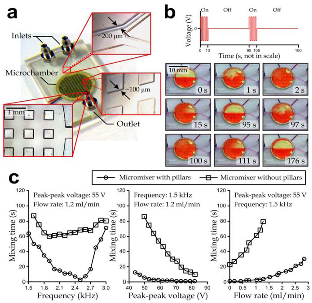
Operation of the active micromixer is based on the mechanical vibration of liquids in the mixer chamber, generated by piezoelectric oscillation of a lead zirconate titanate (PZT) ceramic mounted underneath the mixing chamber diaphragm. Similar to the characterization of the micropump unit, we manufactured the individual active micromixer devices (Figure 4(a)), each consisting of mainly a PMMA substrate and a biocompatible PDMS-coated piezoelectric oscillating diaphragm, in order to investigate their operation performance. The fabrication process was the same as mentioned in the Methods section except that the Tesla valve patterns and the micropump compartments were omitted. Half of the fabricated devices contained arrays of 500 μm (w) × 500 μm (l) × 100 μm (h) microstructured pillars (lower left and lower right insets in Figure 4(a)) in their circular mixing chamber (diameter: 10 mm, height: ~200 μm), while the pillar structures were absent in the other devices. Here, we improved the active mixing by adding arrays of micro-pillar structures in the chamber, in order to further disorder the oscillating liquid flow direction. The spacing of pillars was set as 500 μm to create cavities with a sufficient width to facilitate generation of complex flow profiles such as the circulation behind a backward facing step [39]. Two streams of liquids from the inlets (channel width: 300 µm) of a “Y”-shaped channel (upper inset in Figure 4(a)) were mixed by acoustic mechanical vibration in the mixing chamber and subsequently flowed to the device outlet (channel width: 600 µm).
We conducted experiments to examine the repeatability of the active mixing operation. Two vortex micropump devices were connected to an active micromixer with silicon tubing (internal diameter: 2 mm). Driving voltages of the micropumps were both set as 1.5 V (equivalent to 1.2 mL/min total liquid flow rate), generated by a dual-output power supply (EL302RT, Aim-TTi, Hong Kong, China). The periods of the mixer actuation (peak to peak square-wave voltage: 55 V, frequency: 1.5 kHz) and the typical mixing patterns of the active micromixer with micro-pillars are shown in Figure 4(b). The driving signal of the diaphragm vibration was supplied by a square-wave pulse signal generator (8656B, Hewlett Packard, Palo Alto, CA, USA) and further magnified by a power amplifier (TREK 630, TREK, Medina, NY, USA). To illustrate the mixing performance, two liquids with different colors (water and red dye) were pumped through the inlets. When fluids were passed into the chamber, a sharp and straight interfacial line between water and dye indicated the viscosity-driven laminar flow inside the microchamber (right before 0 s). In this stage, the viscous effect inside the microchamber dominated over advection with ρQD/μ = ReH(D/H) = 0.06 («1), where Q = 1.2 mL/min is the flow rate, D = 10 mm is the chamber diameter, µ ~ 10−3 Pas is the viscosity of water, and ReH is the Reynolds number with the characteristic length H. Once the mixer was actuated at time = 0 s, thorough mixing was observed in the chamber within ~2 s. The corresponding liquid flow was highly unsteady, i.e., the transient effect dominated over both the viscosity (ρfH2/μ > 60 » 1, where f > 1.5 kHz is the vibration frequency of the piezoelectric diaphragm) and advection (H/X = 20 » 1, where X = 10 µm is the average magnitude of diaphragm vibration measured by a laser vibrometer (OFV-3001, Polytec, Irvine, CA, USA)). We expected that the optimal vibration frequency and chamber geometry would vary for different liquid densities and viscosities. As a next step, we turned off the signal generator at 10 s, and subsequently the fluid inside the chamber was reverted to be half red and half transparent. The typical restoring time was within 85 s (time: 10–95 s). At experiment time = 95 s, the input signal was applied to the micromixer again for 10 s for thorough mixing. Then, the input signal was turned off at experiment time = 105 s and separated flow was then observed at t = 176 s. Hence, it is clear that the mechanical vibration induced thorough mixing of flowing liquids inside the chamber. We also demonstrated repeatable results with the mixing time and restoring time both within 5 s and 85 s, respectively, in the two operation periods.
In addition, we performed another set of experiments to further investigate the dominating factors and to verify the mixing enhancement of micro-pillars. We examined the effect of three operation parameters (liquid flow rate, vibration frequency and peak to peak driving voltage) on the mixing time by regulating one of the input values and keeping the other two values constant. The results are shown in Figure 4(c). The results for varying frequency at 55 V peak to peak voltage and 1.2 mL/min liquid flow rate (left) indicated that the optimal operating frequencies for the micromixers with and without pillars were ~2.5 kHz (corresponding to a mixing time of 3 s) and ~1.9 kHz (corresponding to a mixing time of 58 s). The results for varying peak to peak driving voltage reflected that a higher voltage amplitude induced shorter a mixing time (middle). This was due to the more rigorous mechanical vibration of the membrane that enhanced the local liquid oscillation for a better mixing outcome. The results also showed that liquids with a higher liquid flow rate required longer mixing times (right). Additionally to these observations, it should be noted that the micromixers with pillar structures induced shorter mixing times compared to the ones without pillars in all the above-mentioned operation configurations, and so the mixing enhancement induced by pillars was clearly demonstrated. While these results have essentially demonstrated the significant mixing improvement induced by the micro-pillar structures, further quantitative characterization of the mixing mechanism can provide guidelines for device optimization.
Figure 4.
(a) Fabricated active micromixer device. Top inset: “Y”-shaped channel region. Right inset: projection view of micro-pillars. Bottom inset: mixing chamber exit; (b) Representative time-lapse images of dual-stage micromixing operation. Under a defined mixing operation arrangement (top), the flowing liquids were repeatedly mixed and de-mixed via the mixer activation and deactivation, respectively, as shown in the microscopic image snapshots (bottom); (c) Mixing characteristics as functions of pumping flow rate, peak to peak voltage and oscillating frequency of mixer driving signals. Three sets of experiments were performed by varying the oscillating frequency (left), peak to peak voltage (middle) and pumping flow rate (right), respectively, while the other two parameters were fixed for each individual case.

3.4. Concentration Regulation of the Microfluidic Mixing Module Array
Experiments were further conducted to generated solution mixtures with different volumetric ratios between liquids from the two inlets. Water and red dye were pumped with different flow rates form inlet 1 and 2, respectively; and their flow rates were adjusted individually by their corresponding vortex micropumps. An interfacial cutoff between the two liquids was clearly observed in the chamber without mixing operation. Different widths of the liquids at the center cross-section of the chamber (d1 and d2) are indicated in Figure 5(a). The flow patterns for different pumping ratios shown in Figure 5(b) indicate that the ratio between the liquid widths in the chamber reflected that of the effective driving voltages, which were the voltage levels beyond the minimum driving voltage (Vo = 0.66, V as mentioned). To effectively characterize the operation of the mixing module array, we defined three parameters to normalize the ratios between driving voltages of the micropumps (voltage index), widths of the unmixed liquids (width index) and color intensities (color index) of the liquids inside the mixing chamber as described in the Appendix. (In the case of only one liquid flowing from either inlet 1 or inlet 2, all the three values equal “1” or “−1”, respectively; and they equal “0” for a balanced flow from the two inlets.) Results (Figure 5(c)) shows that both the width index (R2 = 0.9988) and color index (R2 = 0.9974) strongly correlated with the voltage index. Therefore, the microfluidic mixing module array developed in this work can precisely generate output solutions with defined concentrations by regulating the driving voltages of the two inlet micropumps with a relatively high production rate (~1–2 mL/min).
Figure 5.
(a) Top view of a mixing module during operation with the micromixer deactivated; (b) Representative profiles of flowing liquids with (bottom row) and without (upper row) mixing operation corresponding to different effective voltage inputs of the micropumps: 0.3 V:0.8 V (left), 0.4 V:0.4 V (middle) and 0.6 V:0.3 V (right); (c) Width index and color index as functions of voltage index. These index parameters are defined in the Appendix.

4. Conclusion
We successfully designed and developed an integrated microfluidic mixing module array including vortex micropumps, Tesla microvalves and active micromixers for continuous solution supply with real-time tunable concentrations. This microfluidic device was micro-fabricated based on photolithography of SU-8. Chemically inert materials (PMMA and PDMS) were used as the inner flow surfaces to achieve the biocompatibility for potential clinical and biochemical applications. Due to the digital controllability of the device, we also developed an external manifold device driver and an interface program to automate operations of the microfluidic components and to achieve the overall system portability. We characterized the vortex micropump units using the classical centrifugal pump theory that states that the flow rate governed by the micropumps is proportional to the driving voltage. Each micropump can deliver a wide range of flow rates and pumping pressures up to 0.850 mL/min and 1.831 kPa at ~2.5 V, respectively. Additionally, we also investigated the functionality of the active micromixer units for the required thorough mixing time according to different operation configurations: Liquid flow rate and magnitude (peak to peak driving voltage), and frequency of the mechanical diaphragm vibration underneath the mixing chamber. We validated the significant mixing enhancement of the micro-pillar array fabricated inside the chamber. Optimal mixing time of the pillar-equipped mixers could be achieved by mixing within 5 s for liquid outflow >1 mL/min. The optimal oscillation frequency of the input voltage was 2.5 kHz and 1.9 kHz for the mixing chambers with and without micro-pillars, respectively.
Furthermore, we demonstrated the integrated microfluidic mixing module array to deliver and mix multiple liquids with adjustable volumetric ratios. Concentrations of the output mixtures could be precisely regulated (R2 > 0.99) by different driving voltages of micropumps. In essence, we have demonstrated a technology that can be further integrated with other microfluidic components for complex sample preparation, delivery and detection. In particular, the system integration will potentially automate the high-throughput bio-fluids/chemicals processes requiring significant sample volume (>0.1 mL/min) into a single versatile polymer-based microfluidic chip for biomedical applications such as drug delivery [40], molecular analyses and gene screening [25].
Acknowledgments
We acknowledge financial support from the City University of Hong Kong (project# 7200267 and 9610216). We would like to thank Thomas K. F. Lei (currently with the Chang Gung University, Taiwan) for the early development of the vortex micropump. Wen J. Li would also like to thank The Chinese University of Hong Kong for its partial financial support of this project.
Appendix
S1. Automated Driver System for the Microfluidic Mixing Module Array
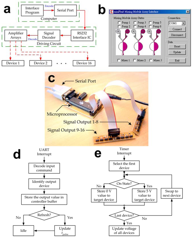
Interface hardware and software were developed to control the microfluidic mixing module array and eventually to automate the entire bio-fluid delivery and transport processes. As mentioned in the main text, both the vortex micropump and active micromixer units were controlled by electrical signals and thus automation of our microfluidic system could be achieved by amplifying driving signals from a computer. A unified handheld automated driver system was established to simultaneously operate multiple microfluidic devices and the basic operation flow is described in Figure S1(a). Users could either manually inputting commands or coding operation sequence and parameters to an interface program (Figure S1(b)) to regulate flow rates of the micropumps and switch on/off the mixing operation. These input parameters then transmitted via the serial port to a manifold device driver shown in Figure S1(c), which decoded the received commands and drove the multiple microfluidic units up to 16 channels simultaneously.
Technically, each motor driver circuit was composed of three integrated circuit chips: a microcontroller (AT90S8515, Atmel, San Jose, CA), a serial port encoder/decoder (MAX232, Maxim, Sunnyvale, CA) and an operational amplifier. The electrical signals from the device driver were programmed in the pulse-width modulation (PWM) format, followed by a voltage averaging circuit to convert the pulse signals into the equivalent steady voltage levels. Since the ratio between the equivalent driving voltage Veq and the peak voltage Vpeak was equal to the ratio between its pulse width tpulse and signal period T, we adjusted tpulse to regulate flow rate of each micropump by Veq ≈ Vpeak × (tpulse/T) based on the micropump characteristics described in Figure 4c. In our automated driver system, we set Vpeak = 5 V and T = 3.9 ms, so the target Veq was generated by regulating tpulse between ~0.4 ms and ~2 ms. For the mixing operation, an additional module integrated with a relay-based oscillating signal generator circuit (peak to peak voltage: 55 V, frequency: 1.5 kHz) was inserted between the micromixer and the device driver to generate the required electrical signals. The micromixers were then actuated by digital signals (on/off) from the driver.
Figure S1.
(a) Operation flow of the automated driver system; (b) Layout of the interface program; (c) Digitally controllable manifold device driver; (d–e) Flow diagrams of (d) UART and (e) timer interrupt functions implemented by our automated driver system.
Figure S1.
(a) Operation flow of the automated driver system; (b) Layout of the interface program; (c) Digitally controllable manifold device driver; (d–e) Flow diagrams of (d) UART and (e) timer interrupt functions implemented by our automated driver system.

It should be noted that the microfluidic mixing module array often required parallel operation, i.e., multiple microfluidic devices operate with different output parameters together. Due to the fact that the information contained by each serial port data package was limited to an 8-bit integer, we adopted a specific transmission protocol such that the operation parameters of various microfluidic units were temporarily stored in the device driver. Thereby the microfluidic units kept their defined operations until an updating command was received and so the parallel operation of multiple units was ensured. In detailed, the microcontroller processed command data and PWM signals with the Universal Asynchronous Receiver/Transmitter (UART, Figure S1(d)) and the timer interrupt (Figure S1(e)) functions, respectively. The microcontroller kept swapping the output voltages to generate PWM signals using the timer interrupt function. When an external command was received from the serial port of a computer, the UART interrupt function instantly transferred the corresponding output values to the buffer storage and check whether updating of the output voltages was needed. If so, the system subsequently altered the output PWM signals for the target microfluidic unit, while others units continued their operations without any interruption.
S2. Definitions of Voltage, Width and Color Indices
The voltage index V is defined by V = (V1 – V2)/(V1 + V2), where V1 and V2 are the effective driving voltages (the voltage levels above the minimum driving voltage of micropumps, i.e., Vo = 0.66 V) of micropump 1 and 2 shown in Figure 1(a), respectively.
The width index d is defined by d = (d1 – d2)/(d1 + d2), where d1 and d2 are the widths of flowing liquids along the center chamber cross-section from inlet 1 and 2, respectively, without mixing operation.
The color index C is defined by C = (2C3 – C1 – C2)/(C2 – C1), where C1 and C2 are the average color intensities in the chamber of the liquids from inlet 1 and 2, respectively, without mixing; and C3 ≈ (C1d1 + C2d2)/(d1 + d2) is the average color intensity of mixture in the chamber.
References
- Harrison, D.J.; Fluri, K.; Seiler, K.; Fan, Z.; Effenhauser, C.S.; Manz, A. Micromachining a miniaturized capillary electrophoresis-based chemical analysis system on a chip. Science 1993, 261, 895–897. [Google Scholar]
- Thorsen, T.; Maerkl, S.J.; Quake, S.R. Microfluidic large-scale integration. Science 2002, 298, 580–584. [Google Scholar]
- Melin, J.; Quake, S.R. Microfluidic large-scale integration: The evolution of design rules for biological automation. Annu. Rev. Biophys. Biomol. Struct. 2007, 36, 213–231. [Google Scholar] [CrossRef]
- Fettinger, J.C.; Manz, A.; Lüdi, H.; Widmer, H.M. Stacked modules for micro flow systems in chemical analysis: Concept and studies using an enlarged model. Sens. Actuat. B: Chem. 1993, 17, 19–25. [Google Scholar] [CrossRef]
- Xia, Y.; Whitesides, G.M. Soft lithography. Annu. Rev. Mater. Sci. 1998, 28, 153–184. [Google Scholar] [CrossRef]
- van Lintel, H.T.G.; van de Pol, F.C.M.; Bouwstra, S. A piezoelectric micropump based on micromachining of silicon. Sens. Actuat. 1998, 15, 153–167. [Google Scholar]
- Chen, C.; Santiago, J.G. A planar electroosmotic micropump. J. Microelectromech. Syst. 2002, 11, 672–683. [Google Scholar] [CrossRef]
- Unger, M.A.; Chou, H.P.; Thorsen, T.; Scherer, A.; Quake, S.R. Monolithic microfabricated valves and pumps by multilayer soft lithography. Science 2000, 288, 113–116. [Google Scholar]
- Vandelli, N.; Wroblewski, D.; Velonis, M.; Bifano, T. Development of a MEMS microvalve array for fluid flow control. J. Microelectromech. Syst. 1998, 7, 395–403. [Google Scholar] [CrossRef]
- Bau, H.H.; Zhong, J.; Yi, M. A minute magneto hydro dynamic (MHD) mixer. Sens. Actuat. B: Chem. 2001, 79, 207–215. [Google Scholar] [CrossRef]
- Stroock, A.D.; Dertinger, S.K.; Ajdari, A.; Mezic, I.; Stone, H.A.; Whitesides, G.M. Chaotic mixer for microchannels. Science 2002, 295, 647–651. [Google Scholar]
- Bedö, G.; Fannasch, H.; Müller, R. A silicon flow sensor for gases and liquids using AC measurements. Sens. Actuat. A: Phys. 2000, 85, 124–132. [Google Scholar]
- Dijkstra, M.; de Boer, M.J.; Berenschot, J.W.; Lammerink, T.S.J.; Wiegerink, R.J.; Elwenspoek, M. Miniaturized thermal flow sensor with planar-integrated sensor structures on semicircular surface channels. Sens. Actuat. A: Phys. 2008, 143, 1–6. [Google Scholar] [CrossRef]
- Wu, J.; Ye, J. Micro flow sensor based on two closely spaced amperometric sensors. Lab Chip 2005, 5, 1344–1347. [Google Scholar] [CrossRef]
- Tay, F.E.H. Microfluidics and BioMEMS Applications; Kluwer Academic Publishers: Norwell, MA, USA, 2002. [Google Scholar]
- Breslauer, D.N.; Lee, P.J.; Lee, L.P. Microfluidics-based systems biology. Mol. Biosyst. 2006, 2, 97–112. [Google Scholar] [CrossRef]
- DeMello, A.J. Control and detection of chemical reactions in microfluidic systems. Nature 2006, 442, 394–402. [Google Scholar] [CrossRef]
- Sia, S.K.; Whitesides, G.M. Microfluidic devices fabricated in poly(dimethylsiloxane) for biological studies. Electrophoresis 2003, 24, 3563–3576. [Google Scholar] [CrossRef]
- McClain, M.A.; Culbertson, C.T.; Jacobson, S.C.; Allbritton, N.L.; Sims, C.E.; Ramsey, J.M. Microfluidic devices for the high-throughput chemical analysis of cells. Anal. Chem. 2003, 75, 5646–5655. [Google Scholar]
- Zare, R.N.; Kim, S. Microfluidic platforms for single-cell analysis. Annu. Rev. Biomed. Eng. 2010, 12, 187–201. [Google Scholar] [CrossRef]
- Rohde, C.; Zeng, F.; Gonzalez-Rubio, R.; Angel, M.; Yanik, M. Microfluidic system for on-chip high-throughput whole-animal sorting and screening at subcellular resolution. Proc. Natl. Acad. Sci. USA 2007, 104, 13891–13895. [Google Scholar]
- Vasdekis, A.E.; Laporte, G.P.J. Enhancing single molecular imaging in optofluidics and microfluidics. Int. J. Mol. Sci. 2011, 12, 5135–5156. [Google Scholar] [CrossRef]
- Warrick, J.; Meyvantsson, I.; Ju, J.; Beebe, D.J. High-throughput microfluidics: improved sample treatment and washing over standard wells. Lab Chip 2007, 7, 316–321. [Google Scholar] [CrossRef]
- Gomez-Sjoberg, R.; Leyrat, A.A.; Pirone, D.M.; Chen, C.S.; Quake, S.R. Versatile, fully automated, microfluidic cell culture system. Anal. Chem. 2007, 79, 8557–8563. [Google Scholar]
- Battersby, B.J.; Trau, M. Novel miniaturized systems in high-throughput screening. Trends Biotechnol. 2002, 20, 167–173. [Google Scholar] [CrossRef]
- Studer, V.; Pepin, A.; Chen, Y.; Ajdari, A. An integrated AC electrokinetic pump in a microfluidic loop for fast and tunable flow control. Analyst 2004, 129, 944–949. [Google Scholar] [CrossRef]
- Yang, Z.; Matsumoto, S.; Goto, H.; Matsumoto, M.; Maeda, R. Ultrasonic micromixer for microfluidic systems. Sens. Actuat. A: Phys. 2001, 93, 266–272. [Google Scholar] [CrossRef]
- Rife, J.C.; Bell, M.I.; Horwitz, J.S.; Kabler, M.N.; Auyeung, R.C.Y.; Kim, W.J. Miniature valveless ultrasonic pumps and mixers. Sens. Actuat. A: Phys. 2000, 86, 135–140. [Google Scholar] [CrossRef]
- Munsondonald, B.R.; Young, Y.; Okiishi, T.H.; Huebsch, W.W. Fundamentals of Fluid Mechanics, 6th ed; John Wiley & Sons: New York, NY, USA, 2008. [Google Scholar]
- Nguyen, N.; Wu, Z. Micromixers—A review. J. Micromech. Microeng. 2005, 15, R1–R16. [Google Scholar] [CrossRef]
- Bottausci, F.; Mezic, I.; Meinhart, C.D.; Cardonne, C. Mixing in the shear superposition micromixer: Three-dimensional analysis. Philos. Trans. A Math. Phys. Eng. Sci. 2004, 362, 1001–1018. [Google Scholar] [CrossRef]
- Chou, H.-P.; Unger, M.A.; Quake, S.R. A microfabricated rotary pump. Biomed. Microdevices 2001, 3, 323–330. [Google Scholar] [CrossRef]
- Oddy, M.H.; Santiago, J.G.; Mikkelsen, J.C. Electrokinetic instability micromixing. Anal. Chem. 2001, 73, 5822–5832. [Google Scholar] [CrossRef]
- Yang, Z.; Goto, H.; Matsumoto, M.; Maeda, R. Active micromixer for microfluidic systems using lead-zirconate-titanate(PZT)-generated ultrasonic vibration. Electrophoresis 2000, 21, 116–119. [Google Scholar] [CrossRef]
- Tesla, N. Valvular Conduit. U.S. Patent 01329559, 21 February 1916. [Google Scholar]
- Morris, C.J.; Forster, F.K. Low-order modeling of resonance for fixed-valve micropumps based on first principles. J. Microelectromechan. Syst. 2003, 12, 325–334. [Google Scholar] [CrossRef]
- Tuzson, J. Centrifugal Pump Design; John Wiley & Sons: New York, NY, USA, 2000; pp. 61–89. [Google Scholar]
- Turton, R.K. Rotodynamic Pump Design; Cambridge University Press: New York, NY, USA, 1994; pp. 1–10. [Google Scholar]
- Lin, C.M.; Lai, Y.S.; Liu, H.P.; Chen, C.Y.; Wo, A.M. Trapping of bioparticles via microvortices in a microfluidic device for bioassay applications. Anal. Chem. 2008, 80, 8937–8945. [Google Scholar]
- Tsai, N.-C.; Sue, C.-Y. Review of MEMS-based drug delivery and dosing systems. Sens. Actuat. A: Phys. 2007, 134, 555–564. [Google Scholar] [CrossRef]
© 2012 by the authors; licensee MDPI, Basel, Switzerland. This article is an open-access article distributed under the terms and conditions of the Creative Commons Attribution license (http://creativecommons.org/licenses/by/3.0/).
Share and Cite
MDPI and ACS Style
Lam, R.H.W.; Li, W.J. A Digitally Controllable Polymer-Based Microfluidic Mixing Module Array. Micromachines 2012, 3, 279-294. https://doi.org/10.3390/mi3020279
AMA Style
Lam RHW, Li WJ. A Digitally Controllable Polymer-Based Microfluidic Mixing Module Array. Micromachines. 2012; 3(2):279-294. https://doi.org/10.3390/mi3020279
Chicago/Turabian StyleLam, Raymond H. W., and Wen J. Li. 2012. "A Digitally Controllable Polymer-Based Microfluidic Mixing Module Array" Micromachines 3, no. 2: 279-294. https://doi.org/10.3390/mi3020279