1. Introduction
Precise fluid flow control is a key requirement in many reaction, production or analytical processing systems. Over the past decade, miniaturization of complex fluidic systems has led to many new and potential applications, including microreactor assemblies [
1], microscale chemical analysis systems [
2] and medical systems such as rapid DNA sequencers [
3] and drug micro-dosers [
4]. However, the need for a small-volume, high-precision mass flow controller for minute fluid flows has not yet been fulfilled. A typical mass flow controller can be modeled as shown in
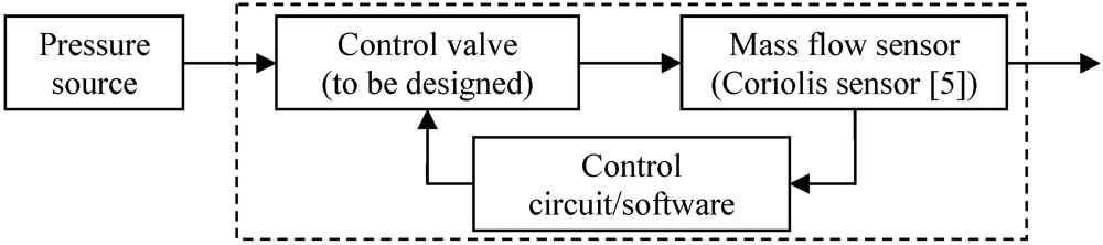
Figure 1. It consists of a mass flow sensor, a proportional control valve and control electronics connected in a closed control loop, set to adjust flow to a specific set point.
Figure 1.
Functional model of a typical mass flow controller (dashed box), consisting of a control valve, flow sensor and control circuit.
Figure 1.
Functional model of a typical mass flow controller (dashed box), consisting of a control valve, flow sensor and control circuit.
In recent research a new micromachined mass flow sensor has been developed based on the Coriolis principle, capable of measuring mass flows up to 1.2 g/h with an accuracy of 10 mg/h [
5]. To apply this sensor in a low-throughput mass flow controller, a microvalve capable of proportionally controlling such tiny flows is required. The potential applications of such a miniature mass flow controller include the following:
Evaporation systems for the production of solar cells, requiring a very stable flow rate without overshoot;
Microreactors for flow chemistry, demanding chemical compatibility and low leakage for safety reasons;
Gas and liquid chromatographs, requiring a very stable flow rate and a large dynamic control range to facilitate both high-pressure and low-pressure flows;
Dosing systems for the food production and pharmaceutical industries, demanding high control precision and easily cleanable or replaceable components;
Flow control for medical purposes, e.g., in blood pressure measurement systems, requiring compatibility with the human body.
Other common applications of dosing systems include lab-on-a-chip, point-of-care test systems or in-situ drug micro-dosers. A review of the strengths and weaknesses of various microfluidic platforms for these applications can be found in [
6].
This paper analyses the requirements and challenges associated with fabricating a low-throughput microvalve for continuous mass flow control. First a set of specific performance demands are formulated based on the intended applications listed above. Subsequently, the basic concepts used in existing designs are analyzed with respect to functionality and technology. Finally, we describe the predominant actuation schemes and evaluate them for their application in a micromachined control valve. Proceeding from these analyses, we identify the design concepts and actuation schemes that we think are best suited for the proportional control valve.
2. Basic Design and Operating Principle
Given a certain differential pressure, controlling fluid flow requires control over the flow resistance of at least one element in the flow circuit. In most cases, this resistance change is achieved by changing the mechanical geometry. Some non-mechanical alternatives have been reported, such as electro-capillary [
7] or diffuser microvalves [
8], but since there is no actual closure these systems cannot guarantee low leakage. They are therefore not considered in this review.
A basic design of a mechanical control valve is shown in
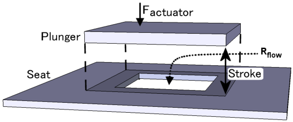
Figure 2, consisting of an orifice in a fixed plate (the valve seat), which is covered by a vertically translating plunger. The maximum flow supported by the valve is defined by the structural dimensions—specifically, the diameter of the orifice and the separation between the two plates. The maximum separation that can be achieved is called the stroke. The leakage performance of a valve is determined by the closing surface area, the relative surface roughness and flatness of seat and plunger and the force by which the plunger is pressed against the seat.
Figure 2.
Typical structure and operating principle of a microvalve. The moving plunger covers an orifice in the valve seat, thus changing the flow resistance.
Figure 2.
Typical structure and operating principle of a microvalve. The moving plunger covers an orifice in the valve seat, thus changing the flow resistance.
Mechanical microvalves are commonly divided into active and passive systems,
i.e. with and without a powered actuator. Passive valve designs are not evaluated in this study, because they are either one-way flow rectifiers [
9] or designed to control a single, specific flow [
10].
In order to achieve precise control over a range of flows, a powered actuator is required. The maximum actuator force determines the maximum differential pressure across the valve, as the actuator needs to be able to counteract the fluid force acting on the plates. The maximum actuator stroke limits the valve stroke, unless a mechanical amplification scheme is applied. The actuator also defines the power dissipation of a control valve, as well as its open-loop response time.
3. Valve Specifications
Many properties determine the performance of (micro) valves, including flow range, control precision, leakage flow, power usage, speed, physical dimensions and dead volume. The specific set of demands for any microvalve design is determined by its application.
For the applications listed in
Section 1, translating the demands into quantitative values leads to the specifications listed in
Table 1. Taking gas chromatography as an example, the requirement of controlling both high and low-pressure gas sources leads to a high demanded dynamic control range. Typical flow rates could be 20 mL/min helium at a pressure difference of 2 bar on the one hand, and 1,500 mL/min argon at a pressure difference of 100 mbar [
11] on the other hand. This also means the microvalve must have a fine resolution of flow control.
Table 1.
Operational specifications of the desired microvalve.
Table 1.
Operational specifications of the desired microvalve.
| | Specification | Influenced by |
|---|
| Max flow range | 1 g/h (liquids), 100 sccm (gases) | Orifice diameter/Stroke |
| Flow control resolution | 0.1 mg/h (liq.), 0.01 sccm (gas) | Resolution of plate separation |
| Leakage | <10−6 mbar L/s He | Seal surface area/Relative roughness & flatness |
| Max. differential pressure | >10 bar | Closing force |
| Static operating power | <100 mW | Actuator/Dimensions |
| Settling time | <1 ms | Actuator/Dimensions |
| Dimensions | <10 × 10 × 10 mm3 | |
The signal-to-noise ratio in the detectors is strongly dependent on the stability of the flow rate and the sample purity, so a good stability of the valve in open state as well as low leakage of the valve in closed state is absolutely necessary. The leakage specification of 10−6 mbar L/s helium is typical for most macro-scale applications. It will be particularly challenging to obtain this performance at the microscale, because closure forces are limited in small-volume, low-power actuators.
A typical value for the closed-loop settling time of an entire mass flow controller is 100 ms, which is generally dominated by the response time of the flow sensor and the stabilization of the fluid flow. To ensure that the valve does not become a limiting factor, an open-loop response time of 1 ms is demanded for the microvalve. Finally, the total valve volume should be kept as low as possible, so that the flow control system as a whole remains compact and easy to integrate.
4. Valve Concepts
At the macroscopic scale a wide range of valve designs exists for a large variety of applications. Gate valves, ball valves, poppet valves and needle valves are just a few common examples. In contrast, the diversity in microvalve designs is far smaller; in fact, the vast majority of valve designs at the micro scale are based on the same principle, namely using a vertically translating plunger to cover a tube or orifice. This concept—illustrated in
Figure 3(a)—was used for the first valve micromachined in silicon, as reported by Terry
et al. [
12], and has been applied with modifications in a large number of later designs. However, other valve concepts do exist, although they are applied less frequently. This section will give an overview of these concepts and will highlight their key advantages and drawbacks.
Figure 3.
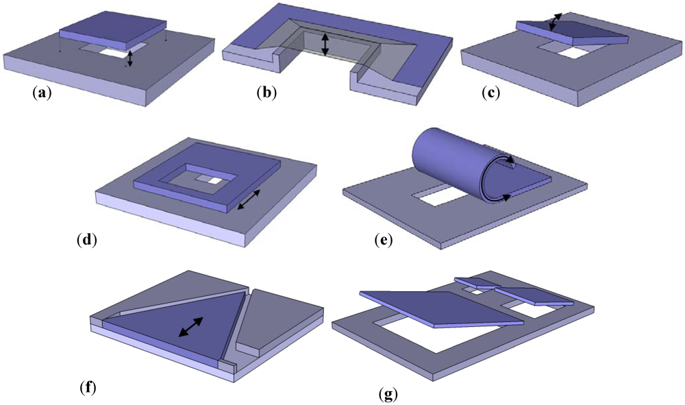
Schematic drawings of several microvalve design concepts. (a) Vertically translating plate; (b) Vertically translating membrane (cross-section); (c) Tilting plate; (d) Horizontally translating plate; (e)Bending plate; (f) Needle (planar); (g) Scaling valve array.
Figure 3.
Schematic drawings of several microvalve design concepts. (a) Vertically translating plate; (b) Vertically translating membrane (cross-section); (c) Tilting plate; (d) Horizontally translating plate; (e)Bending plate; (f) Needle (planar); (g) Scaling valve array.
4.1. Vertically Translating Plate Valves
Refinements of the vertically translating plate concept have led to many different microvalve designs. With the development of advanced silicon micromachining processes, the nickel diaphragm was commonly replaced with silicon, or silicon-derivative materials [
13]. However, there are two important disadvantages of using hard materials such as nickel or silicon.
First, obtaining a leak-tight seal between two plates with high Young’s modulus is challenging, as they will not readily deform to match each other’s surface topography. It has been reported in [
14] that the flatness of typical silicon wafers (~60 nm peak-peak across sub-millimeter scales) is already too large to obtain good closure. A possible solution for this problem has been reported by Yanagisawa
et al. [
15]. It uses conformal layer deposition to fabricate a plunger shaped (nearly) identical to the seat surface, which is released from the seat using sacrificial layer etching. Because of the nearly perfect fit between seat and plunger, an exceptionally low leakage flow of 6 × 10
−9 mbar L/s is achieved [
16].
The second disadvantage to using hard materials is that any particle landing in between the seat and plunger will prevent the valve from closing fully. Thus, in order to crush such particles and allow the valve to close, actuator pressures of the order of thousands of bars become required [
17]. A possible solution to this particle sensitivity was presented by Chakraborty
et al. [
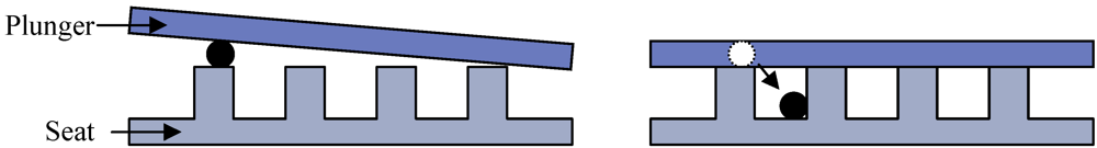
18]. By etching concentric grooves in the valve seat surface, as shown in
Figure 4, particles can be trapped away from the closing surfaces. This approach has however not yet been proven successful, as no leakage performance data were published for this valve, even though it was specifically aimed at low-leakage aerospace applications.
Figure 4.
Trapping of particles in grooves etched in a hard plate.
Figure 4.
Trapping of particles in grooves etched in a hard plate.
4.2. Flexible Membrane Valves
A common modification of the translating plate concept is to replace the rigid plate by a flexible membrane that wraps over the valve seat(s), as shown in
Figure 3(b). The advantage of using membrane closure is that the plunger can elastically deform to match the precise shape and curvature of the valve seat, improving the seal and so reducing leakage flow. Dust particles can also be enveloped by the membrane, reducing the required actuator force at the cost of a slight increase in the required stroke. This reduction in force requirements may however be offset by an increase in stiction, which occurs when the seat and plunger remain in close contact for a prolonged period of time.
When the flow channel is fabricated entirely out of flexible material, the design comes close to the pinch valve concept at the macroscopic scale. Such valves are highly tolerant of particles and other contaminants, which makes them well suited to the control of slurry-like fluids and use in contaminated environments.
The primary disadvantage of membrane closure is the increased fragility. Specifically thin membranes made from high Young’s modulus materials may easily rupture, due to the large stress caused by the deformation strain. Excessive strain can occur during fabrication, for example if a sharp-edged particle is introduced into the system, or when the pressure difference between the channel and the surroundings becomes too great. It is therefore common to use materials with low Young’s modulus such as silicone rubber [
19,
20] or PDMS [
21,
22].
Compared to rigid materials, elastomers typically have a reduced chemical resistance and higher permeability to moisture and gases. Some highly inert elastomers do exist, such as the commercially available Viton
® and Kalrez
® fluoroelastomers [
23]. The latter is however only available as pre-fabricated sheets and seals, making it difficult to apply in a microfabricated design. Yang
et al. reported the use of a thin layer of parylene as an addition to silicone rubber, to counteract the gas penetration [
20].
Another disadvantage of elastomers is the increased stiction between seat and plunger, caused by an increase of contact area as the elastic material conforms more closely to the underlying morphology. A possible solution to this problem is to gradually peel the plunger off the seat surface [
22].
4.3. Tilting Plate Valves
A second modification of the “translating plate” concept is to fix one side of the plunger to the surrounding bulk. This turns a translating motion into a tilting motion, as shown in
Figure 3(c). With an appropriately chosen pivot point, this geometry can supply an amplification of actuator stroke (or force). An early tilting plate design was reported by Ohnstein
et al., using a flexible beam fixed on one side to the bulk [
24] as shown in
Figure 5. An electrode embedded in the beam enabled direct electrostatic attraction to the substrate, but due to the electrostatic pull-in effect the valve suffered from very poor control precision (see
Section 5.3).
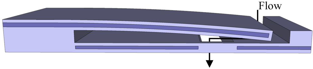
A design better suited to flow control applications is used in the commercially available NC-1500 Fluistor, shown schematically in
Figure 6. This valve uses thermal actuation, where the formation of evaporation bubbles creates a small expansion of a movable membrane. This small initial stroke is then transferred so that the actuator and plunger tilt away from the valve seat over a larger distance [
25,
26].
Figure 5.
Electrostatic tilting plate microvalve [
24].
Figure 5.
Electrostatic tilting plate microvalve [
24].
Figure 6.
Design and operating principle of the NC-1500 Fluistor, a commercially available tilting plate microvalve [
25].
Figure 6.
Design and operating principle of the NC-1500 Fluistor, a commercially available tilting plate microvalve [
25].
4.4. Bending Plate Valves
A more elaborate variation on the tilting plate concept utilizes specific materials, or combinations of materials, to fabricate a plunger that detaches itself from the valve seat. Material properties, such as thermal expansion, piezoelectric strain or phase-change shape memory, can be applied to obtain plates that bend or curl away from the valve orifice, as shown in
Figure 3(e). The gradual “peeling” of the plate can significantly reduce the force required to overcome plate stiction. It can also allow for precise flow control, provided the actuation has sufficient resolution. A drawback is the large bending moment created by the fluid pressure on the necessarily compliant plate, which leads to low leakage performance at large differential pressures.
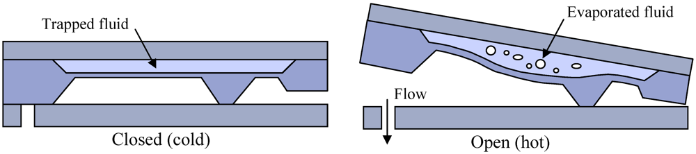
A variation of the bending plate scheme that could circumvent this problem was presented by Watanabe
et al., as shown in
Figure 7 [
27]. It uses an annular piezoelectric disc that contracts radially in the in-plane direction, eliminating any moving parts in the third dimension and so reducing the total volume of the device. Because the actuation direction is perpendicular to the fluid pressure, the stiffness in the direction of the fluid pressure can be increased without penalty.
Figure 7.
Annular disc actuation scheme presented by Watanabe
et al. [
27].
Figure 7.
Annular disc actuation scheme presented by Watanabe
et al. [
27].
4.5. Horizontally Translating (Sliding) Plate Valves
A concept intuitively well suited to flow control applications is the use of a horizontally translating or sliding plate to vary the overlap between two orifices, shown in
Figure 3(d). Apart from straightforward control, a big advantage of such a design is that it can be made to require zero power in the steady state.
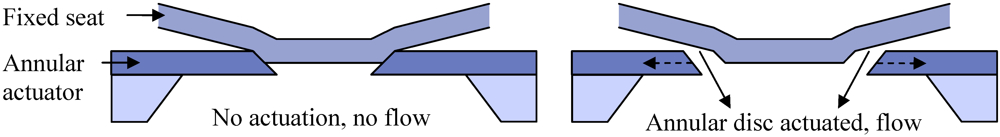
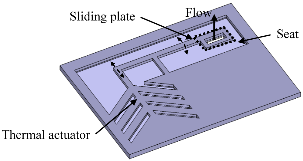
The sliding motion can be executed linearly, in rotation or using a pivoting structure. The latter design is used in a valve reported by Williams
et al. [
28] and shown in
Figure 8. Thermal expansion of silicon rods pushes a perforated plate across the valve seat, changing the overlap of the orifices.
Figure 8.
Horizontally translating plate microvalve using thermal actuation in a pivoting design [
28]. The dashed line marks the perforated plate, which overlaps with the inlet and outlet orifices.
Figure 8.
Horizontally translating plate microvalve using thermal actuation in a pivoting design [
28]. The dashed line marks the perforated plate, which overlaps with the inlet and outlet orifices.
In contrast to its good control properties, the sliding or rotating plate concept suffers from very poor leakage performance. This is because the sliding movement takes place in the same plane as that in which the channel closure needs to be achieved. For low-force, high-precision actuation it is desirable to have low friction between the two plates, whereas good closure requires pretension between the plates, which leads to friction. Thus there is an inherent tradeoff between friction and closure. The valve presented by Williams illustrates this problem, as it is designed to always keep the plate floating.
4.6. Needle Valves
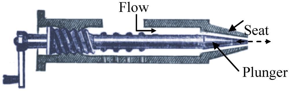
The needle valve is a macroscopic scale design commonly used when precise flow control is required. It uses a tapering plunger moved into a tapered valve seat, commonly implemented as a sharp needle such as shown in
Figure 9. The good control properties stem from the large ratio between the needle’s length and its diameter: A large axial translation leads to only a small change in radial closure, allowing for very precise flow control. These valves can also be made to have low leakage, by using the large closing area between the needle and the tapered seat.
The needle valve concept can be applied at the microscale as well, although the reduced dimensions mean the total closure contact is significantly reduced. This, in combination with the limited pressures available from micro-actuators, increases the demands on the contact between plunger and seat significantly. To obtain low-leakage closure, the surfaces must be made exceptionally smooth and flat with respect to each other so that they can fit closely together. It should be noted that the planar design illustrated in
Figure 3(f) is not well suited to low leakage, because of the inherent tradeoff between friction and closure due to the sliding motion of the needle.
Figure 9.
Macro-scale needle valve, using a tapered plunger (needle) to increase closure contact and controllability [
29].
Figure 9.
Macro-scale needle valve, using a tapered plunger (needle) to increase closure contact and controllability [
29].
4.7. Scaling Valve Array
The scaling array concept shown in
Figure 3(g) is not a valve design in itself, but can be used as an extension of all valve designs presented above. By fabricating an array of microvalves and opening and closing each valve separately, the total flow through the array can be controlled digitally. This allows the use of on/off bistable microvalve designs, or actuation schemes unsuited to proportional control, while maintaining the required flow control precision. The array can be constructed with all valves equal, by which the flow scales linearly with the number of open valves, or with exponentially scaling valve dimensions, which would allow binary control.
Applying the scaling array concept increases the total device footprint, but also increases the leakage flow considerably. For full binary control with a 1:10,000 resolution, a total of 14 on/off valves would be required. Consequentially, the leakage demands would also be increased by a factor of 14.
5. Actuators
As stated in
Section 2, the type and specifications of the actuator have a great influence over the performance of a microvalve. Because the choice of the optimal actuator and the design and operation of the microvalve are mutually dependent on each other, it is difficult to choose any one actuator type as the best. To allow a relatively objective comparison between microvalve actuators, this study focuses on the response time, for which the requirements have been defined in
Section 3, and the work density, which measures the maximum work an actuator of a certain volume can deliver.
Power consumption is also an important measure for actuator performance, but it can be greatly influenced by the operating mode of the microvalve. Therefore no explicit comparison will be made for this metric. So-called “stick and slip” stepper actuators are not considered here, as they are extensions of more general actuator types. Typically, they offer increased stroke lengths at the expense of decreased actuation speed [
30].
5.1. Thermal Expansion Actuators
Thermal expansion actuators are based on Joule heating of materials, usually applying bilayer strain mismatch or other forms of stroke amplification [
31,
32,
33]. A more elaborate approach, known as thermopneumatic actuation, uses the expansion of a trapped working fluid [
25]. This gives more flexibility in the choice of membrane material, but the sealing of the fluid makes the fabrication process more complex. However, typical settling times for thermopneumatically actuated microvalves in the literature are of the order of seconds [
34], rendering them unusable for the flow control applications targeted here.
An actuation scheme very similar to thermopneumatics is to use materials capable of shape changing under thermal, chemical, optical or electrical stimuli. Recent examples are hydrogel [
35], ionogel [
36] or electrochemical actuators [
37]. Similar to thermopneumatic actuators, they suffer from very long response times on the order of seconds to minutes, which is too slow for mass flow control.
The work density of a thermal expansion actuator for an ideal elastic load has been derived by Brouwer [
38]. For a slim, prismatic beam of volume
V at an average temperature difference
ΔTavg with the surroundings, the maximum work density
ξmax is:
where Fbl is the blocking force at zero extension, Δlmax is the maximum stroke without load, α is the thermal expansion coefficient of the beam material and Ey is the Young’s modulus of the beam material.
Because thermal actuation is based on a temperature change, the speed of these actuators is limited to the heating and cooling of materials. The time constant for the thermal expansion of a slim, uniform beam of length
l0 has been approximated in [
33] to be:
where Cp is the specific heat capacity, ρ the density and λ the thermal conductivity of the material.
Two common expander materials are (poly)silicon and polyimide.
Table 2 shows the work densities and response times for 1 mm long beams of these two materials. Although polyimide requires a lower temperature to reach the same work density as polysilicon, and thus is more energy efficient, its low thermal conductivity makes it too slow for valve applications. The response time of polysilicon is within range of the demands listed in
Section 3.
Table 2.
Work density and response time of common materials in thermal expansion actuators [
38].
Table 2.
Work density and response time of common materials in thermal expansion actuators [38].
| Title | Ey [N∙m−2] | α [K−1] | Cp [J∙kg−1∙K−1] | ρ [kg∙m−3] | λ [W∙m−1∙K−1] | ΔTavg [K] | ξmax [J∙m−3] | τ [s] |
|---|
| Silicon | 1.6 × 10¹¹ | 2.6 × 10⁻⁶ | 700 | 2,400 | 157 | 600 | 4.9 × 10⁴ | 1.1 × 10⁻³ |
| Polyimide | 2.5 × 10⁹ | 5.5 × 10⁻⁵ | 2,000 | 1,420 | 0.16 | 250 | 5.9 × 10⁴ | 1.8 |
5.2 Shape Memory Alloy Actuators
Shape memory alloy (SMA) is a special type of thermal actuator that applies a specific material phase change, which occurs in some metal alloys, such as NiTi, under the influence of temperature. SMA actuators are known for offering higher work densities than any other MEMS actuator, of the order of 10
6 or 10
7 J/m
3 [
39,
40], and therefore have been applied in a wide range of micromechanical systems over the past decades [
41]. However, similar to many other thermal actuators, thermal phase change actuators suffer from very long response times, ranging from tens of milliseconds to several seconds [
34,
42]. Another major disadvantage is that the performance of SMA actuators significantly decreases after thousands of cycles [
43], while proportional controllers require several orders more actuator cycles during their lifespan.
5.3. Electrostatic Actuators
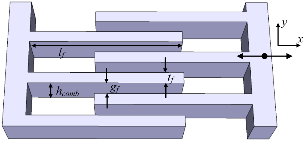
Electrostatic actuators are commonly used in MEMS because they are relatively easy to integrate in silicon fabrication processes. They offer a very high speeds if resistance and capacitance is kept low, and they show low power usage in steady state. However, the strongly nonlinear relation between electrode separation and electrostatic force leads to the so-called ‘pull-in’ effect, which makes direct electrostatic actuation unsuitable for proportional control. A design that (partially) solves this problem is the laterally driven comb drive, which uses the fringing field between interdigitated electrodes to generate work [
44]. It supports larger strokes than gap-closing designs (on the order of 100 µm), but can deliver only very small forces (<1 mN).
Figure 10.
Definitions of structural dimensions in a lateral comb drive, with motion along the x-axis.
Figure 10.
Definitions of structural dimensions in a lateral comb drive, with motion along the x-axis.
The maximum energy that a lateral comb drive transfers to an elastic suspension has been derived to be [
38]:
where
n is the number of finger pairs,
ε is the dielectric constant of the gap between the fingers,
gf is the gap spacing,
hcomb is the height of the comb fingers,
U is the voltage across the gap and
s is the stroke of the actuator, which in the ideal case equals the finger length
lf (see
Figure 10). If the gap width
gf is limited by the spatial resolution of the fabrication process, the minimum thickness of the fingers
tf will be equal to
gf. If the width of the comb drive equals two times the finger length
lf, the minimum volume of the comb drive then becomes:
The maximum work density then equals:
where
Ee is the electrical field in the gap. Assuming an electrical field of 100 MV/m, the maximum work density for a lateral comb drive in air becomes 2.2 × 10
4 J/m
3. Considering that an actual comb drive will have a larger volume than the minimum derived above, this value will be lower in practice. Comb drives can typically be driven at frequencies of the order of 10
4 Hz or higher [
44], meaning that the response time is well below 1 ms.
5.4. Electromagnetic Actuators
Electromagnetic actuators use the net Lorentz force on a current-carrying wire in a magnetic field. In the micro domain the current density can be high, because the heat generated due to resistivity in relation to the heat transport is low. The current density is not limited by the temperature rise of the coil, as in macro-scale Lorentz actuators, but by electromigration. Because of this limit, the current density
J can remain constant when scaling down the device [
38]:
where r represents the scaling factor, defined as the length scale of typical dimensions in a device. The deliverable work density of a Lorentz actuator can be described as:
where FL is the Lorentz force, s is the total stroke, Vcm is the coil volume opposing the magnet and Bavg is the average flux density in the coil. Therefore, the work density scales linearly with reducing dimensions, meaning the performance decreases significantly at higher levels of integration. The work density for a realizable Lorentz actuator design measuring 700 × 500 µm2 has been calculated by Brouwer to be approximately 150 J/m3.
This highly limited work density leads to very poor actuator performance in small-scale designs. Meckes
et al. presented an integrated, planar electromagnetic coil design for use in a microvalve, which had a diameter of approximately 1 mm and was reported to generate an actuator force of 0.8 mN [
45]. For a total valve area of 1 mm
2, this actuator would be capable of withstanding only 8 mbar of differential pressure.
An advantage of electromagnetic actuators is that they can be placed outside of the valve chamber, with the magnetic field coupling to magnetic materials inside the valve. This is commonly done using large external coils, particularly for testing purposes. A micromachined design applying this concept was demonstrated by Sadler
et al., using NiFe flux guides to couple the magnetic field to a NiFe membrane in the valve chamber [
46].
5.5. Piezoelectric Actuators
Piezoelectric actuators use the strain of piezoelectric materials that is induced when they are submitted to an electric field. This strain is limited to approximately 0.1% of the original size, but it can be delivered with very large forces of the order of kilonewtons. The limited stroke is commonly amplified using bimorph membranes or a leverage mechanism, or by creating stacks of actuators. Piezo actuators offer high speeds and very low power consumption in the steady state [
47], but typically require high voltages of the order of 100 V. They also often contain hazardous substances, such as lead in Pb[Zr
xTi
1−x]O
3 (PZT), meaning the actuator must remain separated from the fluid in many applications.
For a beam of piezoelectric material with length
l0 and strain coefficient
d31, the maximum work density using an ideal elastic load can be derived to be [
38]:
where Fbl is the blocking force, Δlmax is the maximum stroke, E3,max is the maximum electrical field between the electrodes, A is the surface area of the beam cross-section and c11 is the ratio of longitudinal stress to longitudinal strain. For PZT, currently the best performing piezoelectric material, typically c11 = 150 × 109 N/m2, d31 = 100 × 10−12 and E3,max = 40 × 106 V/m. This results in a maximum work density of 3 × 10⁵ J/m3. Commercially available stack piezos smaller than 10 × 10 × 10 mm3 typically offer actuation forces of the order of hundreds of Newtons with strokes up to 10 µm, corresponding to work densities of the order of tens of kJ/m3.
Micromachining of thin-film piezoelectrics can be accomplished in silicon technology [
48]. This is of interest to large-scale integration applications, but with layer thicknesses of the order of micrometers such actuators will not have enough volume to offer large work. Furthermore, the integration of piezoelectric films in the microfabrication process can significantly reduce the thermal budget available for further processing steps [
49].
6. Conclusions
In this paper we have described design considerations for a micromachined proportional control valve for very small flows. We have formulized a set of demands based on a range of specified applications. Based on these demands we have surveyed a number of basic microvalve design concepts and analyzed their suitability for use in the envisioned control valve. A valve’s capability to control flow is deemed the most important specification, but the leakage performance is also given high weight, as good closure is difficult to obtain at the micro scale. The results of this analysis are summarized in
Table 3 below.
Table 3.
Summary of the valve concepts described in
Section 4.
Table 3.
Summary of the valve concepts described in Section 4.
| | Flow control | Leakage performance | Design freedom |
|---|
| Translating plate | ○ | ○ | + | Many designs reported |
| Translating membrane | ○ | + | Matches seat topography, may be permeable to gases | − | Limited to thin or elastic materials |
| Tilting plate | + | Large Stroke : ΔRflow ratio | ○ | ○ |
| Bending plate | + | (Assuming sufficient actuator resolution) | − | Pliable materials susceptible to buckling | − | Limited to specific (actuating) materials |
| Sliding plate | ++ | Plate position directly determines Rflow | −− | Tradeoff between friction and closure | ○ |
| Needle | ++ | Very large Stroke : ΔRflow ratio | ○ | Large contact surface, but needs high conformity | ○ |
| Scaling array | ++ | Resolution scales with number of sub-valves | −− | Demands scale with number of sub-valves | ○ |
Precise flow control can best be achieved by using a horizontally translating (sliding) plate design or a needle valve. The first suffers from severe leakage, whereas the latter poses very high demands on the relative roughness and flatness of the plunger and seat. An alternative is the tilting plate design, which can be made to have the same advantage as the needle valve.
Good closure performance can be obtained from using soft, elastomer materials, capable of shaping themselves to match the valve seat surface and of embedding contaminants in the microvalve assembly. They do however suffer from increased valve stiction, reduced chemical resistance and increased permeability for gases. It is therefore preferable to use harder, more resistant materials, for which the challenge to achieve good closure lies with obtaining very high conformity between seat and plunger.
Proportional control of fluids requires an actuator, and only a few types of actuator are capable of fulfilling the requirements outlined at the beginning of this paper. The properties of the discussed actuators are summarized in
Table 4. Thermal expansion and shape memory alloy actuators are used in many designs, but cannot offer high enough speeds for high bandwidth control applications. Electrostatic actuators are very fast, but the pull-in effect in gap-closing designs makes them poor control actuators. The lateral comb drive circumvents this problem, but while it can be designed for relatively large strokes, it can only deliver very small forces.
Table 4.
Summary of the actuator types described in
Section 5.
Table 4.
Summary of the actuator types described in Section 5.
| | Work density [J/m3] | Response time | Integration |
|---|
| Thermal expansion | <105 | ○ | Strongly material-dependent | + | Standard materials supported |
| Shape memory alloy | <107 | −− | >10 ms–10 s | ○ |
| Electrostatic | <104 | + | <1 ms | + | Standard materials supported |
| Electromagnetic | <103 at microscale | ○ | Limited by drive current electronics | ○ |
| Piezoelectric | <105 | + | <1 ms | − | Volume limitations, low thermal budget |
Micromachined electromagnetic and piezoelectric actuators suffer from severely decreased performance with respect to their macro-scale counterparts: The work density of electromagnetic actuators decreases with increasing level of integration, while micromachined piezoelectrics are very limited in layer thicknesses. This problem can be avoided by using macroscopic scale components, but this is disadvantageous for wafer-scale fabrication as the assembly of fine machined devices cannot easily be automated.
Given its high work density, high speed and low power usage, piezoelectric actuation is considered the best candidate for the proportional control valve, but unless the integration compatibility is significantly improved it will remain challenging to obtain the required performance at a manageable level of complexity.


