Review

Hydrodynamic Flow Confinement Technology in Microfluidic Perfusion Devices

Department of Chemical and Biological Engineering, Chalmers University of Technology, Kemivägen 10, 412 96 Göteborg, Sweden
*
Author to whom correspondence should be addressed.
Micromachines 2012, 3(2), 442-461; https://doi.org/10.3390/mi3020442
Submission received: 24 March 2012 / Revised: 18 April 2012 / Accepted: 2 May 2012 / Published: 10 May 2012
(This article belongs to the Special Issue Micro Flow Controllers)

Abstract

:
Hydrodynamically confined flow device technology is a young research area with high practical application potential in surface processing, assay development, and in various areas of single cell research. Several variants have been developed, and most recently, theoretical and conceptual studies, as well as fully developed automated systems, were presented. In this article we review concepts, fabrication strategies, and application areas of hydrodynamically confined flow (HCF) devices.

1. Introduction

Microfluidic devices for processing nano- and picolitre volumes of liquids is now a well established technology, of great benefit to molecular biology, diagnostic medicine [1], and various branches of analytical chemistry [2]. Closed-channel configurations, operating in a laminar flow regime, are the most common implementation of microscale fluid handling technology today, well suited for the small volume samples in pharmacology, proteomics, DNA analysis and other life science areas [3]. The number of practical applications of microfluidics is rapidly growing, and the commercial availability of devices and methods is progressing accordingly. Recent technological developments, in particular droplet microfluidics [4], are expected to further facilitate and advance this trend. Moreover, the drive to integrate various on-chip detection schemes with sample handling and analyte separation in the context of chemical and medical analytics led to a new class of microfluidic devices, the micro-total analysis systems (µTAS) [5]. The fabrication of closed channel microfluidic devices is generally achieved through top-down microengineering techniques [6,7,8]: lithography of quartz, glass and silicon substrates [9], soft lithography employing various polymers [10], and layered (laminate) technologies, for example utilizing paper or polymeric thin films [11].
However, in many important instances a closed channel microfluidic device is not a practical solution, even though sample size, flow velocity and other requirements are in the optimal range [6]. For example, it is difficult or often impossible to interact with selected surface regions surfaces or small surface adhered objects, such as tissue slices or single biological cells. In this context, perfusion of biological cells with chemical solutions is an important experimental procedure, often performed for the purpose of drug testing or screening, for studies of ion channel activity, chemical signaling and other properties and features of single cells. In order to perform these tasks in closed channel microfluidic devices, the cells have to be introduced into the channel structure, manipulated to the desired position, kept alive under spatially confined conditions, and often exchanged or removed from the channels [12]. Growing cells in microscale channels is subject to limits imposed by the diffusion dominated material transport in confined volumes, which can have a detrimental effect on cell growth. Moreover, the spatially controlled delivery of small amounts of liquid to a larger surface area—for instance in order to create defined patterns on a surface, achieve localized surface functionalization, or perfuse regions of tissue slices—goes beyond the abilities of closed channel devices [13].
A fresh approach to the problem was introduced a few years back with the development of open channel microfluidic devices [14], exploiting regions of coexisting flows at the exits of multiple parallel channels for cell perfusion. As microflows are typically laminar, several streams of fluid can flow in parallel in the same channel without converging into each other (
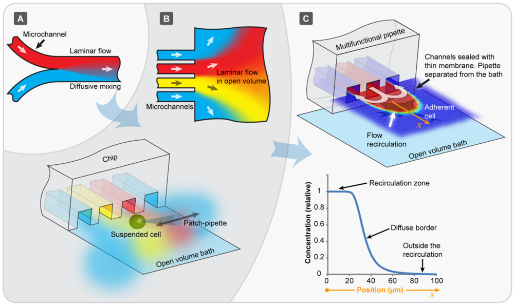
Figure 1(A)). Diffusion dominates the exchange of molecular species in those parallel streams, and equilibration is achieved on a short timescale of seconds to minutes. This feature allows for diffusional mixing as the sole mode of transport between flows, and can be used to control separation and the progress of chemical reactions. When such laminar microstreams exit into an open volume (Figure 1(B), upper panel), the pattern remains parallel for a short distance before they diverge and merge. If a cell is manipulated through such a fluidic arrangement (Figure 1(B), lower panel), very short solution exchange times, at the order of a few milliseconds, can be achieved. The flows are typically generated by means of applying air pressure to wells located at the opposite end of the channels. Open volume devices shortened the times necessary to perform dose-response determinations on single cells tremendously, but suffered from a number of drawbacks. Over time, the open volume becomes contaminated by the outflow from the channels. It is even more problematic that cells have to be picked up individually, and micromanipulated to the channel exits.
An elegant practical solution to these problems is offered by a fairly new microflow concept, which uses a dynamically defined open volume principle rather than pre-defined, closed or open channels for confinement and delivery of fluids (Figure 1(C)). Hydrodynamically confined flow (HCF) devices are a modern class of microfluidic flow cells, where a small rapidly moving volume of fluid is spatially confined within another, significantly larger fluid volume. The two miscible or immiscible liquids are physically in contact, separated only by means of a dynamically created virtual boundary (Figure 1(C) top panel). The transport of molecules across the boundary is only possible by diffusion. The boundary can be sharply defined (Figure 1(C), bottom panel), and in practical terms be controlled by adjusting the ratio between the inflow and outflow rate.
Figure 1. Evolution of chip-based perfusion microfluidics. (A) Conventional microchannel in a laminar flow regime. The different colors represent individual solutions of different compositions which coexist in the streams and mix only by diffusion; (B) Open volume microfluidic devices, where parallel microchannels lead into an open bath, where the individual streams coexist for a short distance. Arrays of densely packed chemical environments are formed by the flows from neighboring microchannels. When a suspended cell is translated through these environments very fast (10 ms range), rapid solution exchange around the single cell is achieved highly effectively; (C) The hydrodynamically confined flow device technology is a similar, but more recent concept, where the beneficial features of laminar flow are available outside the physical device boundaries for an extended period of time. A confined volume is created at the device tip, where active convection out-competes diffusion. Contamination of the open volume is prevented, and the device can be positioned close to surface adhered cells and tissues.
Micromachines 03 00442 g001
The idea of a dynamic fluid confinement was first published in 2003 by Feinerman and Moses [15], who described the use of a picoliter “fountain-pen” constructed from co-axial dual glass pipettes. This inspiring device allowed delivery of a liquid to an arbitrary location within the open bath, and contamination of the surrounding bath by the inflowing reagents is effectively avoided. This early device has its drawbacks in practical use. For example, upscaling of fabrication is impractical, and small errors in positioning in close proximity to the surface will instantly break the delicate glass assembly. The first report of a microfabricated device of this kind, which overcomes these limitations, arrived soon thereafter. It appeared as recently as 2005 in a publication [16], where the term “hydrodynamic flow confinement” was also coined.
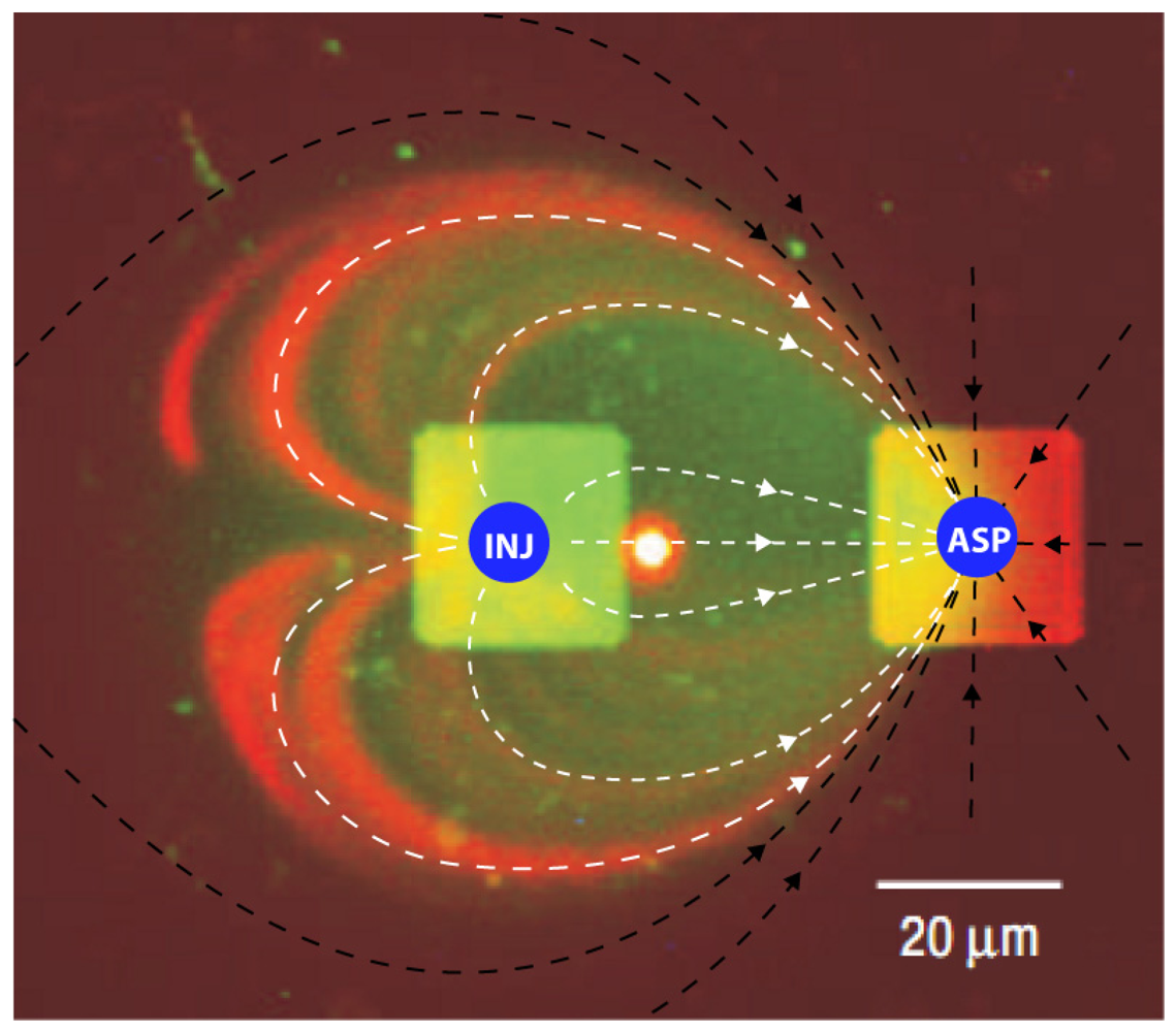
The operation principle of a hydrodynamically confined flow device is illustrated on the minimal two-channel configuration in Figure 2. One channel serves as injection port or outlet (positive pressure), where liquid is introduced into an open volume, and one as aspiration port or inlet (negative pressure), through which liquid is removed from it. Figure 2 shows a micrograph of the exits of two adjacent channels into an open volume, overlaid with arrows depicting the flow lines. The inflow into the aspiration port consists mainly of the open bath liquid (black lines in Figure 2), and partially of the fluid injected through the outlet channel into the flow field of the aspiration channel (white lines in Figure 2). The stream exiting from the outlet channel is confined and directed into the aspiration channel.
Figure 2. Fluorescence micrograph, providing the view through an open volume onto the two quadratic channels of a microfluidic device which generates a hydrodynamically confined flow. The aqueous flow from the injection channel (outflow) contains fluorescein and red fluorescent beads to directly visualize the flow lines. The open volume appears dark. White arrows depict the flow lines of the injection channel outflow, black arrows the flow lines of the open volume medium. INJ: injection channel (outflow), ASP: aspiration channel (inflow). The image was adapted with permission from [16]. 2005 Nature Publishing Group.
Micromachines 03 00442 g002
In order to achieve hydrodynamic confinement, the flow rate of the aspiration flow must be higher than the flow rate of the injection flow, and the outflow to inflow ratio must be smaller than a critical value. The ratio for the device in Figure 2, featuring 20 × 20 µm channels with 30 µm separation, and an injection flow rate of 0.44 nL/s, is ~0.4. The boundary between the confined and the open volume is diffusive; its width is determined by the solution exchange time, i.e., the time a molecule stays in the confined volume, and its diffusivity. The experimental conditions necessary to achieve efficient confinement, while inhibiting diffusion across the virtual boundary, are characterized by low Reynolds and high Péclet numbers.
There is currently only a relatively small number of HCF devices presented in the literature, as this novel class of device has just started to progress into a research area [16,17,18,19,20,21,22,23,24,25,26,27]. The pronounced advantages of the technology, being highly localized confinement, the ability to work on adherent cell cultures, and the possibility to use familiar and well-established culture protocols, come at the cost of low throughput. HCF devices are limited to relatively slow movements inside the open volume, as rapid shifts in position cause turbulences and distortions of the confined volume, which causes loss of confinement and contamination of the open volume. HCF devices are currently best suited for adherent single cell handling [16,19], some excel in surface processing [24,27] and analysis [23], and others can be advantageously applied to tissue cultures [18], which are typically too large to be introduced into closed channel devices. Some devices can be used in conjunction with other probes, such as patch clamp needles or external electrodes [26]. Despite the low throughput characteristics, the high spatial resolution and contamination-free fluid delivery renders HCF devices as valuable research instruments for many applications that require localized perfusion.
The developments reported by several different research groups are summarized in Table 1. Technologically closely related flow devices, which do not employ hydrodynamic confinement, but feature similar channel arrangements and in/out-flow concepts with an exposed liquid volume, are included for comparison. These can be considered milestones in the development of the HCF devices, and have their own interesting set of applications, for example in electrochemical surface analysis and in parallel assay technology. Highlighted in the table are typical materials and fabrication as well as application parameters, working distances and applications as reported in the original publication.
Figure 3. 
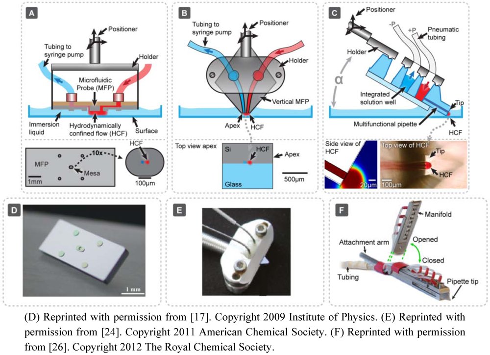
Hydrodynamically confined flow devices. (A) The microfluidic multipurpose probe [16,17], fabricated from a planar silicon dice. It features one injection port and one aspiration port and is positioned in parallel orientation to the surface;(B) The vertical microfluidic probe [24], constructed from a bonded silicon-glass quadrilateral, held in place by a holding clamp. It is identical in channel arrangement and function to the microfluidic multipurpose probe (MFP), but fabrication has been facilitated. The channel outlet face of the chip is also oriented parallel to the surface of interest, such that the surface is in full contact with the confined volume; (C) The multipurpose pipette [26], fabricated as a bonded PDMS-glass composite. This device creates a hydrodynamically confined volume at the tip of a pipette-shaped device, which is pressurized via on-chip wells confined within a holding interface. This device can be positioned at an angle α to the surface, since the three channel design with one injection port and two adjacent aspiration ports is supported by a thin bottom membrane, which allows close surface proximity. The fabrication procedure for the multilayered PDMS device by Queval et al. [18] is similar to the one depicted here, but requires an alignment of the channels prior to bonding;(DF) Photographic images of the devices of (A–C), as shown in the original publications.
Micromachines 03 00442 g003
Figure 3 summarizes three current concepts of hydrodynamically confined flow devices, the microfluidic multipurpose probe (MFP), the vertical microfluidic probe (vMFP), and the multifunctional micropipette (MFπ), pioneered by different research groups. They represent chronologically major steps in the development of the concept from the earliest reported device [16], via a considerable conceptual improvement, in particular with respect to fabrication complexity [24], to the most recent HCF pipette [26]. The three different devices are also representative of typical material choices, ranging from silicon, via a silicon glass hybrid to PDMS elastomer. The fabrication strategies and applications are very briefly discussed further in the text. Figure 3(A), depicts schematically the microfluidic probe developed by Junker et al. from IBM. From design and idea, but not necessarily from principle, it may be considered a remote descendant of IBM’s classic ink jet printing technology [16].
The device consists of a flat silicon plate of cm2 dimensions with two central microscale orifices on a central mesa-like structure, one for solution inlet and one for outlet. For operation, it is arranged parallel to the surface of interest, and submerged in a shallow bath of fluid. It is held at a fixed distance of a few micrometers (cf. Table 1) by four protruding corner posts. The plate is interfaced by supply tubes, and can be positioned by a micromanipulation device. When positive pressure is applied to the injection port and a moderate vacuum to the aspiration port, a stream of liquid moves through the bath and creates a defined volume of fluid, which is spatially confined to the region between surface and silicon mesa. The red color represents the inflow (injection) into and the blue color the outflow (aspiration) from the open volume. A part of the open volume is simultaneously drawn into the outflow channel. This open volume component is typically the major share of the total inflow volume, which is fundamental to define the hydrodynamic confinement. In this two-cannel device, the close proximity of the surface is preferred to prevent fluid from escaping the confinement. The lower panel in Figure 3(A) displays the bottom plate of the device together with an enlarged view of the mesa. Figure 3(D) shows a photograph of this device, as presented in the original publication. Figure 3(B) schematically displays a design modification of the MFP, termed the vertical microfluidic probe [24]. The large silicon bottom plate of the earlier design has been replaced by a tetragonal Si/glass composite with a flat, polished apex, which can be clamped and interfaced by a sealing holder. In order to achieve efficient interaction of the out-flowing liquid with the surface, this design still requires parallel alignment of the channel outlet plane with the surface. The generation of the confined volume is commensurate to the MFP, fluid circulation is also achieved through tubing and syringe pumps. The photograph in Figure 3(E) shows the device protruding from its holder, which has in- and outflow tubing attached. Both MFP and vMFP are fabricated from silicon or bonded silicon/glass. Somewhat disadvantageous for use with upright microscopes is the vertical positioning. The vertical probe eliminates some of the problems, since it is rather small and at least partly transparent. Inverse microscopes are accessible, even though a means of precise positioning might be advisable, such as a motorized stage. The multifunctional pipette (MFπ), depicted schematically in Figure 3(C) and as a photograph in its interface/holder in Figure 3(F), overcomes these problems by both using a transparent material combination and a design which allows positioning at an angle to the surface. The MFπ is a three-channel device, with one central injection, and two adjacent aspiration ports in the same plane. This arrangement improves the confinement around the injection channel, and reduces the danger of device failure due to aspiration channel clogging. An important functional feature of the device is the 10–30 µm thin transparent bottom membrane, which allows it, just like the coaxial pipette [15], to be manipulated close to an object of interest on the surface. In contrast to the coaxial pipette, the MFπ tip is entirely fabricated from PDMS elastomer, and can be repeatedly brought in contact with the surface without loss of integrity. The flow profile generated by the three-channel arrangement is similar to the one provided by the coaxial fountain pen. It allows free-standing operation, since no fluid can escape the hydrodynamic confinement within the frontal recirculation zone. The lower panel in Figure 3(A) shows a side view (FEM simulation of the concentration profile at the channel outlet) and a top view. The channels are filled with a red colored liquid for visualization. The device further features on-chip fluid reservoirs and microfluidic circuitry and requires only positive and negative pressure supplied through an interface/holder. This pipette opens interesting opportunities in biosciences, pharmacology and clinical research, since it can be co-located with additional probing equipment under most microscopes, and allows highly localized interaction of a chemical or biochemical stimulant with surface-adhered cells and tissue in dish cultures.
The three devices have individual design strengths, which make them attractive research instruments in particular application areas (cf. Table 1). Each of the concepts requires a different set of microfabrication techniques for fabrication and assembly, owing to the materials requirements and, most likely, to the availability of processing equipment and expertise.

2. Fabrication Strategies

2.1. The Microfluidic Probe

The fabrication of the MFP follows a multi-step fabrication route based on traditional silicon processing techniques (Figure 4(A)). Bonding to a PDMS block is employed to obtain closed channel structures. The original publication reports use of double-side-polished silicon wafers as starting material. Three UV-photolithography steps, targeting both sides of the wafer, and two deep-reactive-ion etching (DRIE) steps are required to fabricate the relatively complex structure. After initial photolithography, the top channel structure is etched into the wafer. The wafer is then turned upside-down, and a protective silicon dioxide layer is deposited, photolithographically patterned and etched to pre-define the bottom mesa and the support pillars. A third photolithography step follows in order to create two orifices for the following first DRIE step. After removal of the resist layer, and resist residue ashing, a second DRIE step on the same wafer side produces the bottom mesa and the support pillars. The top channel structure is then activated by oxygen plasma, and bonded to a PDMS slab in order to close the device, and finally interfaced to the liquid supply lines.
Figure 4. (A) Schematic fabrication procedure for the MFP, consisting of essentially three photolithography and two deep reactive ion etching (DRIE) steps. Double-side-polished silicon wafers are used for the procedure. The first two panels depict the fabrication of the upper side of the chip, producing the horizontal channels for liquid supply to the through holes. The next three panels show the SiO2 fabrication to define the locations for mesa and support pillars, followed by the first DRIE step to open the vertical channels. Two photolithography steps are required. The next two panels depict resist removal and a second DRIE step in order to fabricate the bottom geometries. Also shown are the interfacing strategy by means of tubing or fused silica capillaries embedded in a PDMS lid layer, and a three-dimensional representation of the chip, with slightly exaggerated bottom features. Injection and aspiration port are depicted in red and blue, respectively, according to the convention introduced in Figure 2;(B) Fabrication procedure for the vMFP, comprising two photolithography and DRIE steps to define the channels and vias, followed by bonding and polishing. The upper two panels depict the first photolithography and DRIE steps performed on a silicon wafer, which define the channel groves. The next two panels show the opening of the vias by a second cycle of photolithography/DRIE. Note: the second PL is not shown in detail. Subsequently a glass wafer is anodically bonded onto the silicon, and the channels are closed with a low melting point wax, which at elevated temperature is drawn into the structure by capillary forces. The bonded wafer is then diced, and the apex of the rhombic chip is mechanically lapped and polished. Typically, several stacked dices are polished at the same time. The final step involves removal of the wax by submerging the dices in an organic solvent, which dissolves the hydrocarbon based filling. The bottom panel schematically shows a perspective of the flat apex with the channels. Shape and approximate dimensions of the chip are apparent from the photograph of the full device in Figure 2(E);(C) Soft lithography procedure for the fabrication of the MFπ, starting from a PDMS pre-polymer mixture, which is filled into a molding chamber (top panel). The master is a silicon wafer with the channels embossed, typically generated by SU-8 photolithography. DRIE can be employed if a large number of replicas are desired. The casting/curing procedure yields a PDMS slab with imprinted channel grooves. For the purpose of closing the grooves, a thin PDMS membrane is fabricated by spin coating, as depicted in the next panel. The PDMS slab is removed from the molding form and oxygen plasma bonded to the membrane. Holes are punched through the structure in order to connect the channels with the well interior, and the device tip is cut off after alignment under a microscope. A glass support is finally bonded to the underside of the body, leaving a 5 mm end at the pipette tip uncovered. The bottom panel shows the pipette tip geometry obtained by this fabrication procedure.
Micromachines 03 00442 g004
Table 1. Summary of publications of hydrodynamically confined flow (HCF) devices and related exposed-volume microflow technologies.
Publication TitleConfinement 1Main MaterialChannel matrixExposure area and reported working distance (µm)Application angle and positioningSupply systemReported applicationsReference
Planar
Autonomous Microfluidic Capillary SystemNone (conformal)Si2 × 1 (×4)500 × 80; n.a.Planar. FixedOn-chip wells and capillary pumpsMiniaturized immunoassayJuncker et al. [28]
High-sensitivity Miniaturized Immunoassays for Tumor Necrosis Factor a Using Microfluidic SystemsNone (conformal)Si2 × 1 (×11)1000 × 30; n.a.Planar. FixedOn-chip wells and capillary pumpMiniaturized immunoassayCesaro-Tadic et al. [29]
Microfluidic Probe: a New Tool for Integrating Microfluidic Environments and Electronic Wafer-probingNone (conformal)PDMS2 × 1~500 × 500; contactPlanar. FixedSyringeField effect sensing, chemical surface patterningRoutenberg et al. [30]
Confinement of Liquids on SurfacesHydrophilic/-phobic (dry)Si2 × 1180 × 60; n.a.Planar. FixedOn-chip wells and capillary pump Delamarche et al. WO2004050245
Multipurpose Microfluidic Probe & Microfluidic Quadrupole and Floating Concentration GradientHydrodynamic (immersed)Si2 × 1~Ø50–100; 4–50 Planar. FixedExternal from syringe pumpsProtein microarraying, complex gradient formation, surface patterning and staining, single cell detachment, microfluidic quadrupoleJuncker et al. [16,31]
Multilayered Microfluidic Probe HeadsHydrodynamic (immersed)Si2 × 1~Ø50–100; 10 Planar. FixedExternal from syringe pumpsProtein surface patterning, direct processing of photoresistLovchik et al. [17]
Design of Hydrodynamically Confined Micro-fluidics: Controlling Flow Envelope and PressureHydrodynamic (immersed)Si2 × 1~Ø300–900; 50 Planar. FixedExternal from syringe pumpsAntibody surface patterning, direct processing of photoresistChrist et al. [22]
Vertical
Micropatterned Fluid Lipid Bilayer Arrays Created Using a Continuous Flow MicrospotterNone (conformal)PDMS2 × 1 (×48)400 × 600; contactPerpendicular (90˚). FixedOn-chip wells and pressure driveLipid bilayer formationSmith et al. [32]
The Chemistrode: A Droplet-based Microfluidic Device for Stimulation and Recording with High Temporal, Spatial, and Chemical ResolutionNone (conformal)PDMS2 × 1200 × 200; contactPerpendicular (90˚). FixedExternal from syringe pumpsStimulation of mouse pancreas cells and measurement of insulin secretionChen et al. [33]
Microfluidic Push-Pull Probe for Scanning Electrochemical MicroscopyFlow ratio (dry)PET2 × 1~Ø100; contactVariable angleExternal from syringe pumpsSECM of Au surfacesMomotenko et al. [34]
Chamber and Microfluidic Probe for Microperfusion of Organotypic Brain SlicesHydrodynamic (immersed)PDMS3 × 2~Ø40–100; 20Perpendicular (90˚). FixedExternal from syringe pumpsLocal perfusion of organotypic brain slicesQueval et al. [18]
A Vertical Microfluidic ProbeHydrodynamic (immersed)Si/glass2 × 1 or 3 × 110–10,000 (area); 1–80Perpendicular (90˚). FixedExternal from syringe pumpsLocalized chemistry on cell culturesKaigala et al. [24]
A Microfluidic Pipette for Single-Cell Pharmacology & A multifunctional pipetteHydrodynamic (immersed)PDMS3 × 130 × 10–120 × 120; 10 Variable angleOn-chip wells and pressure driveDose response measurements, cell blebbing, ion channel stimulation, co-application with patch clamp needleAinla et al. [19,26]
1 Technologically related flow principles (no hydrodynamic confinement) are included for reference.
The elastomeric silicone rubber not only tightly bonds chemically to the wafer surface, it also allows for pushing thin plastic tubes or fused silica capillaries into stamped-out holes, effectively sealing the tubes without additional sealing efforts. Chips with a surface area of about 3 × 7 mm2 are diced, interfaced with tubing and placed in a holding clamp for application. Further details on the fabrication strategy are provided in a previous publication of the authors on microfluidic networks [35]. The limiting step for process upscaling is the bonding to the PDMS lid. Drawbacks are the complex fabrication with three photolithography and three etching steps, but functional advantages are the possibility of arbitrary channel shapes, arrangements and sizes. Arrays of several channels are not more difficult to produce. A variant of this device with a planar 2 × 2 channel array was later utilized to investigate the concept of fluidic multipoles [31].

2.2. The Vertical Microfluidic Probe

The vMFP has been designed based upon the microfluidic probe discussed above, with the goal to overcome the critical inadequacies concerning practical application and implementation of the original device concept. The MFP is associated with a few limitations and fabrication related problems, which have been addressed by the authors in their latest study [24]. They successfully address artifacts of the earlier technology, including the inability to pattern surfaces in liquid environments, and limitations imposed by the physics of liquid ejection with respect to confinement of chemicals within the targeted surface region. Above all, the fabrication of the vMFP has been simplified by eliminating photolithography steps and introducing some more facile, yet unconventional fabrication steps. Figure 4(B) depicts the full procedure. vMFP heads are designed as silicon/glass hybrids, with channel structures etched as 20 µm deep groves into the 400 μm thick silicon. A slightly thicker glass slide of otherwise identical dimensions is anodically bonded to the silicon in order to obtain closed channels. Since the channels are no longer located on the planar silicon face, but on one of the two sharp points of a diamond shaped chip geometry, which requires a finish by lapping and polishing, the risk of contamination of the channels by silicon dust particles had to be addressed. A solution was achieved through filling the channels with a low melting point wax prior to the polishing step. The wax is removed afterwards by submerging the device in an organic solvent, such as heptane, for several hours. The first four panels in the figure show the initial steps, consisting of two sets of photolithography, which define the channel groves and through holes, respectively, and associated DRIE steps. The next two panels depict bonding and wax filling, which is achieved through capillary forces. The following panels show dicing, polishing and wax removal, followed by a side view of the finished device and a perspective drawing of its polished tip. This procedure consumes less instrument time and processing effort when compared to the fabrication scheme for the MFP, but wax filling and solvent treatment might need special consideration regarding reproducibility and remaining wax traces in the channels. From a functional point of view, this device is clearly easier to interface and integrate. It has a smaller footprint of approximately 1 mm2, which suggest better positioning ability, even though the need for parallel alignment of the channel exit plane to the surface remains an inherited difficulty, which might affect integration with conventional light or confocal microscopes. The original publication recommends a setup for the probe, which includes a two-axis positioning table and tilt-adjustment mechanics. Also discussed are extensions to the flow circuitry, as well as concepts of on-chip filter structures, designed to eliminate the threat of inflow-channel clogging by aspirated material from the surrounding volume.
Design, fabrication and advanced features of the vMFP represent a significant improvement over the MFP. The vMFP is a versatile research device, which unfortunately still requires a specialized stage for mounting and operation. The in-plane design allows for most simple integration of one or more functional elements such as resistive heaters, surface printed electrodes, or sensors. The authors have also demonstrated that by means of side channels, immersion liquid dispensing can be integrated into the probe design, which also allows applying the device to dry surfaces. Upscaling is limited by the polishing step, and the advantage of a more facile fabrication route has to be traded in for the limitation to a linear array of channels. The vertical device developed two years earlier by Queval et al. [18] features a two dimensional array of channels. A soft lithography approach using the optically transparent elastomer poly (dimethylsiloxane) (PDMS) was chosen. The fabrication is very similar to the procedure depicted in Figure 4C, with the difference that the multilayer bonding approach requires an alignment step, which is rather tricky and limits the up-scaling of this process.

2.3. The Multifunctional Pipette

The multifunctional pipette [19] device was designed as a three-channel arrangement, with two aspiration ports adjacent to a center injection channel. Through on-chip solution wells [26] the dead volume and reagent consumption are minimized. The microfluidic network is defined by the replica molding master, and can therefore be easily re-configured according to the experimental requirements. The most important design feature is a thin PDMS membrane defining the bottom plane of the device, which is fabricated by spin-coating of a pre-mixed PDMS membrane, and subsequent curing and plasma-bonding to the device body. The distinct advantage of replica molding, a form of soft-lithography, is the simple fabrication protocol, which does not strictly require clean-room conditions. Soft lithography employs a liquid pre-polymer and a fabrication master, typically a silicon wafer with the channel structure and cutting alignment marks microfabricated onto the surface. Such a master can be produced by a photolithographic process or by DRIE in case a large number of replication cycles are desired. Embossed photoresist structures tend to lift off the surface after several replication cycles, but allow for more rapid changes in design. The choice of pre-polymer includes a number of possible materials, most commonly a mixture of organosilicon polymers mixed with cross-linking catalyst. The multifunctional pipette fabrication was performed using a commercially available poly-(dimethyl siloxane) (Sylgard 184 by Dow Corning), which is readily cured above 65 °C, and has low enough viscosity to allow spin coating for membrane manufacture. Figure 3(C) illustrates the fabrication procedure. PDMS is mixed from two components and filled into a steel or plastics chamber in order to produce the top part of the pipette, including the on-chip wells for solution storage and supply. The chamber consists of a top and bottom part, and is designed to minimize the entrapment of air bubbles. The bottom part of the chamber holds the fabrication master, defining the channel structures, typically for up to 20 pipettes. The resulting PDMS slab is ready to be bonded to the thin bottom membrane, which will seal the channel groves and define the minimum distance of the channels to the surface. This membrane is spin coated onto a hydrophobized silicon wafer. Both the wafer carrying the membrane and the PDMS-filled chamber are heat-treated at 95 °C for 1 h, which cross-links the PDMS pre-polymer. The PDMS slab is removed from the chamber, and the well bottoms are stamped out with a sharp ø 1 mm hole puncher. The slab is subsequently plasma bonded to the membrane-carrying wafer to form an array of devices, which is peeled off and cut into individual devices. The tip of each pipette is cut vertically with microscopic precision along the cutting marks defined in the PDMS structure in order to open the channels. To stabilize the device structure, a 1 mm thick borosilicate microscope glass cover slip, cut to pipette dimensions of approximately 8.5 × 54 mm, is plasma-bonded to the bottom of the device. The bottom panel in Figure 4(C) shows schematically a perspective view of the pipette tip with the channel exit region.
This soft lithography based fabrication process is by far the least complex of the fabrication routes presented. Of distinct advantage are (a) the on-chip wells, which drastically reduce dead volume and facilitate handling and interfacing, and (b) the possibility to incorporate complex microfluidic circuitry into the pipette, such as mixers, gradient generation and fluid switching stages. For most purposes, the MFπ is clamped in a metal or plastic pressure manifold, which can be combined with a holding arm to interface to micromanipulation hardware. The free standing pipette is typically applied at an angle (cf. Figure 2), allowing direct integration with common microscope setups, for example upright or inverse light microscopy and confocal microscopy stations. The pipette is best suited for single-cell manipulation experiments. A functional advantage is the possibility to apply the device at an arbitrary angle, which allows combination with other probes and pipettes under a microscope. Shadowing by the device is also much reduced. Integrated wells lower the contamination risk, as well as sample requirement and dead volumes. The limiting steps for up-scaling are the glass alignment and the required manual cutting of the tip. Disadvantages are the limitation to aqueous solvents, as PDMS swells in organic solvents. The soft material may deform slightly if pressure is applied, which has been improved by the introduction of pressure dampening well close to the pipette tip [26].
Currently, each of the technologies has functional advantages, but also up-scaling limitations, most of which can likely be addressed in the future. For example, the strong benefits of the MFπ and the PDMS version of the MFP, being cheap material and facile production without dedicated cleanroom environment, have to be traded off against the inherently limited compatibility of the soft PDMS polymer towards organic solvents [36]. This disadvantage might not be overly limiting in studies of biological material such as single cells and tissue, since buffered aqueous solutions rather than organic media are typically used in these experiments. It is clear that the use of other materials is possible in all of the designs discussed above, and certainly becomes the subject to future investigation. The MFP allows for arbitrary channel positioning and channel shapes, as the openings are generated by DRIE, which gives a certain advantage over the other two concepts, in particular the MFπ, which is currently limited to linear arrays of rectangular channels.

3. Application Examples

Each of the HCF devices discussed above was designed to provide one or more solution(s) to technological challenges, and in some instances to make microscale processes or scientific experiments feasible which were previously difficult or impossible to perform. The applications, which were reported for each device in the respective original publication, are summarized in Table 1. While similar in principle and operation, the differences in design and implementation give each device its own range of particularly suitable applications. While the silicon and silicon-glass composite probes are useful mainly for chemical surface processing, such as staining, etching, labeling or decorating surface areas or surface-attached objects, the MFπ has its strong side in those single cell experiments, where superfusion and direct or indirect support of other probing techniques is desired. In particular, electrophysiology pipettes (patch clamp), intracellular recording probes, and electroporation electrodes can be used together with the pipette. 
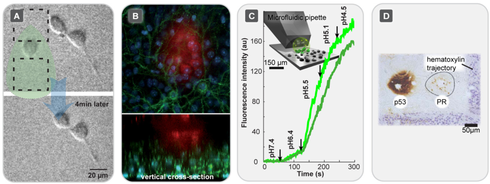
Figure 5 shows application examples for four different HCF devices. In the original publication of the MFP [16] (cf. Figure 2(A)), several application examples were provided. In one example, continuous variation of the scanning velocity of the MFP was utilized to create local concentration gradients, useful for example for patterning surfaces with biomolecules, such as proteins. A MFP with 24 µm separated 40 × 40 µm apertures was positioned 15–20 µm above a substrate covered with fixed NIH3T3 fibroblast cells, and the cells were exposed to a solution of a membrane soluble fluorescent dye, which selectively stained the targeted cells. Figure 5(A) shows another reported example, the selective detachment and collection of a single living cell from a surface, exploiting the shear forces exerted by the moving liquid within the hydrodynamic confinement region. This is on one hand an interesting method for harvesting single adherent cells, but on the other hand illustrates that the HCF technique also poses a certain risk of involuntarily removing cells from the culture plate. The rapid solution exchange achieved by the MFP also suggests applications in chemistry, micro fabrication and surface processing. Mask-less lithography, where photoresistance is developed directly on the size scale of the desired structures, is a promising technique for patterning or modifying planar surfaces. The MFP was reported to be able to write a pattern into an AZ4562 positive photoresist layer of 3 µm thickness, dispensing AZ400K developer as process liquid. The shape of the spots is here determined by the geometry of the HCF region. Figure 5(B) shows the application of a multi-channel version of the MFP for the localized microperfusion of hippocampal organotypic slice from a L15 transgenic mouse. This MFP was made in poly(dimethylsiloxane) and features six micrometre-scale apertures. Each aperture can be used deliberately for either injection or aspiration of solutions, allowing many possible combinations. The MFP used for the perfusion of a small number of cells in a brain slice with concurrent multicolor confocal imaging of the perfused fluorescent dye and fluorescently labeled sub-cellular structures within the tissue. This HCF device offers opportunities for, e.g., studies of neuron interactions where high spatial resolution is required [18]. In Figure 5(C), the application of the MFπ [19] (cf. Figure 2(C)) for a single cell dose-response determination is depicted. This device was designed for carrying out a variety of on-chip fluid processing operations, such as mixing, multiplexing, or gradient generation. Using a fluorescence uptake assay, the generation of dose-response curves in situ from adherent Chinese Hamster Ovary (CHO) cells expressing proton-activated human transient receptor potential vanilloid (hTRPV1) receptors was demonstrated. The pipette served as an automatic solution switching and dilution device in order to supply a sequence of buffer solutions of decreasing pH. A device integrated mixer [37] generated the dilution sequence, which was used to perfuse the targeted cells. Reduced pH (5.4) under calcium-free conditions causes TRPV1 pore dilation, and thus allows for entry of a fluorescent dye into the cell. Further application examples for the MFπ were reported, including membrane bleb formation by exposing selected groups of cells to formaldehyde/dithiothreitol-containing solutions, and the sequential delivery of several active compounds to selected cells by valve-less switching between reagent streams originating from on-chip wells [26]. In Figure 5(D), a recently reported application of the vMFP (cf. Figure 2(B)), termed micro-immunohistochemistry, is shown [27]. By means of this HCF device, nanolitre amounts of antibody solutions were applied to micrometre-sized regions of tissue for their incubation with primary antibodies, which is typical in conventional IHC.
Figure 5. Application examples of HCF superfusion devices. (A) Single Cell Selective Detachment and Aspiration of a Multipurpose Microfluidic Probe (MFP)[16]. Reprinted with permission from [16]. Copyright 2005 Nature Publishing Group;(B) Perfusion of Organotypic Tissue Slices with a Microfluidic Probe [18]. Confocal cross-sections (x-y and z scan) of a hippocampal organotypic slice from a L15 transgenic mouse, recorded during application of the MFP [18]. The cell nuclei (blue), mGFP–labeled pyramidal cells (green) and 10 kDa dextran conjugated to Alexa 647 (red), which is used to superfuse the tissue, are visualized simultaneously. Reprinted with permission from [18]. Copyright 2009 Royal Society of Great Britain;(C) Single Cell Dose Response Measurement using a Microfluidic Pipette (MFπ)[19]. Graphic time series of the dependency of intracellular fluorescence intensity on the pH, obtained by selective exposure of CHO cells with overexpressed TRPV1 ion channels to a pH dilution series generated by means of the pipette. The decreasing pH causes pore dilation and uptake of the fluorescent dye YO-PRO-1. The two traces represent fluorescence intensities measured from two independent cells. Arrows: concentrationswitching times; Inset: illustration of the device application. Reprinted with permission from [19]. Copyright 2009 Royal Society of Great Britain;(D) Immunohistochemistry using a Vertical Microfluidic Probe (vMFP)[27]. Staining of a human ductal carcinoma breast tissue section for the presence of tumor suppressor protein p53 (antibody: monoclonal mouse anti-human α-p53) and human progesterone receptor (antibody: anti progesterone receptor α-PR), with an additional hematoxylin (Natural Black 1) nuclear counterstain. Reprinted with permission from [27]. Copyright 2012 Royal Society of Great Britain.
Micromachines 03 00442 g005
By exchanging the fluids in the supply tubing of the device (cf. Figure 2(B)) the probe was used to stain individual cores of tissue microarrays with multiple antigens. The use of this technology is more preservative of tissue samples and reagents than the conventional technique, and addresses antibody cross-reactivity issues. Different staining conditions can be conveniently applied to a single tissue section.
The reported application examples from a range of fields within biology and microtechnology (cf. Table 1) demonstrate clearly the high potential of the different HCF devices, as they address experimental problems that could not, or only with difficulties, be solved by traditional glass pipette methods, closed channel microfluidic chips or other kinds of traditional or microdevice technology.

4. Summary and Outlook

Hydrodynamically confined flow devices represent a powerful approach to localized solution delivery within a liquid environment that is miscible with the solution to be applied. The greatest strength of the technology is the highly localized exposure, which allows for contamination-free superfusion of micrometer sized surface areas or surface-associated objects. The device concepts published thus far have already shown potential to enable new experimental techniques in the life sciences, where conventional channel microfluidics cannot be applied (cf. Table 1 and references therein). For example, there are limitations associated with performing experimental studies on biological cells in closed microflow devices. Some of the problems arise directly from unfavorable properties of the materials used in device fabrication [38], such as the lack of optical transparency (silicon) and oxygen permeability (glass, silicon), while others are connected to limited compatibility of living cells with microfluidic channel confinement during culture, for example due to gas bubble formation [39]. HCF devices can overcome many of these limitations, and can help to develop new experimental methodologies.
The theoretical understanding of the properties of hydrodynamically confined flows is still far from complete, even though the flow confinement for two channel geometries in close proximity to a surface are well described, and experimentally validated modeling studies have recently appeared [22,31]. This includes investigations of the influence of geometry, flow rate and other parameters on device performance. These studies provide essential data for future HCF device development. Lately, more refined designs, which make the application in single cell and tissue studies very convenient, have been introduced [26]. Advanced application examples, ranging from surface processing over neuropharmacology and membrane protein science to drug delivery and beyond, have already surfaced. They also indicate, as is expected, a trend towards integration of more and more complex fluid processing functionality, including mixing, multiplexing, and diluting capacities into the devices themselves, while their actual use and operation become more convenient and universal. These new generation devices hold promise to become routine tools in single cell and tissue culture experimentation. There is also a strong possibility that the hydrodynamically confined flow, as it is drawn back into the device, can be on-chip processed and analyzed for minute amounts of chemicals released from the stimulated cells and slices. This future scenario is tightly coupled to the progressively improving sensitivity of bioanalytical techniques. Apart from the necessary integration of analytical technology with the HCF devices, fabrication related bottlenecks, which limit production scale-up (cf. Table 1), have to be addressed. It can be anticipated that traditional silicon-based processing methodologies, which are still commonly used, will be largely replaced by more flexible, rapid and cost effective processes.

Acknowledgements

The authors acknowledge the European Research Council (ERC), the Swedish Research Council (VR), the National Institute of Health (NIH), and the Nordic council of Ministers (Nordforsk) for their financial support.

References

  1. Eicher, D.; Merten, C.A. Microfluidic devices for diagnostic applications. Expert Rev. Mol. Diagn. 2011, 11, 505–519. [Google Scholar] [CrossRef]
  2. Ohno, K.; Tachikawa, K.; Manz, A. Microfluidics: Applications for analytical purposes in chemistry and biochemistry. Electrophoresis 2008, 29, 4443–4453. [Google Scholar] [CrossRef]
  3. Cho, S.; Kang, D.K.; Choo, J.; de Mello, A.J.; Chang, S.I. Recent advances in microfluidic technologies for biochemistry and molecular biology. BMB Rep. 2011, 44, 705–712. [Google Scholar] [CrossRef]
  4. Seemann, R.; Brinkmann, M.; Pfohl, T.; Herminghaus, S. Droplet based microfluidics. Rep. Prog. Phys. 2012. [Google Scholar] [CrossRef]
  5. Arora, A.; Simone, G.; Salieb-Beugelaar, G.B.; Kim, J.T.; Manz, A. Latest developments in micro total analysis systems. Anal. Chem. 2010, 82, 4830–4847. [Google Scholar]
  6. Whitesides, G.M.; Stroock, A.D. Flexible methods for microfluidics. Phys. Today 2001, 54, 42–48. [Google Scholar] [CrossRef]
  7. Livak-Dahl, E.; Sinn, I.; Burns, M. Microfluidic chemical analysis systems. In Annual Review of Chemical and Biomolecular Engineering; Prausnitz, J.M., Ed.; Annual Reviews: Palo Alto, CA, USA, 2011. [Google Scholar]
  8. Kenis, P.J.A.; Stroock, A.D. Materials for micro- and nanofluidics. MRS Bull. 2006, 31, 87–94. [Google Scholar] [CrossRef]
  9. Jensen, K.F. Silicon-based microchemical systems: Characteristics and applications. MRS Bull. 2006, 31, 101–107. [Google Scholar] [CrossRef]
  10. Becker, H.; Gartner, C. Polymer microfabrication technologies for microfluidic systems. Anal. Bioanal. Chem. 2008, 390, 89–111. [Google Scholar] [CrossRef]
  11. Martinez, A.W.; Phillips, S.T.; Whitesides, G.M. Three-dimensional microfluidic devices fabricated in layered paper and tape. Proc. Natl. Acad. Sci. USA 2008, 105, 19606–19611. [Google Scholar]
  12. Kim, L.; Toh, Y.C.; Voldman, J.; Yu, H. A practical guide to microfluidic perfusion culture of adherent mammalian cells. Lab Chip 2007, 7, 681–694. [Google Scholar] [CrossRef]
  13. Young, E.W.K.; Beebe, D.J. Fundamentals of microfluidic cell culture in controlled microenvironments. Chem. Soc. Rev. 2010, 39, 1036–1048. [Google Scholar] [CrossRef]
  14. Olofsson, J.; Pihl, J.; Sinclair, J.; Sahlin, E.; Karisson, M.; Orwar, O. A microfluidics approach to the problem of creating separate solution environments accessible from macroscopic volumes. Anal. Chem. 2004, 76, 4968–4976. [Google Scholar] [CrossRef]
  15. Feinerman, O.; Moses, E. A picoliter “Fountain-pen” using co-axial dual pipettes. J. Neurosci. Methods 2003, 127, 75–84. [Google Scholar] [CrossRef]
  16. Juncker, D.; Schmid, H.; Delamarche, E. Multipurpose microfluidic probe. Nat. Mater. 2005, 4, 622–628. [Google Scholar] [CrossRef]
  17. Lovchik, R.D.; Drechsler, U.; Delamarche, E. Multilayered microfluidic probe heads. J. Micromech. Microeng. 2009. [Google Scholar] [CrossRef]
  18. Queval, A.; Ghattamaneni, N.R.; Perrault, C.M.; Gill, R.; Mirzaei, M.; McKinney, R.A.; Juncker, D. Chamber and microfluidic probe for microperfusion of organotypic brain slices. Lab Chip 2009, 10, 326–334. [Google Scholar]
  19. Ainla, A.; Jansson, E.T.; Stepanyants, N.; Orwar, O.; Jesorka, A. A microfluidic pipette for single-cell pharmacology. Anal. Chem. 2010, 82, 4529–4536. [Google Scholar]
  20. Perrault, C.M.; Qasaimeh, M.A.; Brastaviceanu, T.; Anderson, K.; Kabakibo, Y.; Juncker, D. Integrated microfluidic probe station. Rev. Sci. Instrum. 2010, 81, 115107:1–115107:8. [Google Scholar]
  21. Sun, M.; Fang, Q. High-throughput sample introduction for droplet-based screening with an on-chip integrated sampling probe and slotted-vial array. Lab Chip 2010, 10, 2864–2868. [Google Scholar] [CrossRef]
  22. Christ, K.V.; Turner, K.T. Design of hydrodynamically confined microfluidics: Controlling flow envelope and pressure. Lab Chip 2011, 11, 1491–1501. [Google Scholar] [CrossRef]
  23. Cortes-Salazar, F.; Momotenko, D.; Girault, H.H.; Lesch, A.; Wittstock, G. Seeing big with scanning electrochemical microscopy. Anal. Chem. 2011, 83, 1493–1499. [Google Scholar] [CrossRef]
  24. Kaigala, G.V.; Lovchik, R.D.; Drechsler, U.; Delamarche, E. A vertical microfluidic probe. Langmuir 2011, 27, 5686–5693. [Google Scholar] [CrossRef]
  25. Tang, Y.T.; Kim, J.; Lopez-Valdes, H.E.; Brennan, K.C.; Ju, Y.S. Development and characterization of a microfluidic chamber incorporating fluid ports with active suction for localized chemical stimulation of brain slices. Lab Chip 2011, 11, 2247–2254. [Google Scholar] [CrossRef]
  26. Ainla, A.; Jeffries, G.D.M.; Brune, R.; Orwar, O.; Jesorka, A. A multifunctional pipette. Lab Chip 2012, 12, 1255–1261. [Google Scholar] [CrossRef]
  27. Lovchik, R.D.; Kaigala, G.V.; Georgiadis, M.; Delamarche, E. Micro-immunohistochemistry using a microfluidic probe. Lab Chip 2012, 12, 1040–1043. [Google Scholar] [CrossRef]
  28. Juncker, D.; Schmid, H.; Drechsler, U.; Wolf, H.; Wolf, M.; Michel, B.; de Rooij, N.; Delamarche, E. Autonomous microfluidic capillary system. Anal. Chem. 2002, 74, 6139–6144. [Google Scholar] [CrossRef]
  29. Cesaro-Tadic, S.; Dernick, G.; Juncker, D.; Buurman, G.; Kropshofer, H.; Michel, B.; Fattinger, C.; Delamarche, E. High-sensitivity miniaturized immunoassays for tumor necrosis factor a using microfluidic systems. Lab Chip 2004, 4, 563–569. [Google Scholar] [CrossRef]
  30. Routenberg, D.A.; Reed, M.A. Microfluidic probe: A new tool for integrating microfluidic environments and electronic wafer-probing. Lab Chip 2010, 10, 123–127. [Google Scholar] [CrossRef]
  31. Qasaimeh, M.A.; Gervais, T.; Juncker, D. Microfluidic quadrupole and floating concentration gradient. Nat. Commun. 2011, 2. [Google Scholar] [CrossRef]
  32. Smith, K.A.; Gale, B.K.; Conboy, J.C. Micropatterned fluid lipid bilayer arrays created using a continuous flow microspotter. Anal. Chem. 2008, 80, 7980–7987. [Google Scholar] [CrossRef]
  33. Chen, D.; Du, W.; Liu, Y.; Liu, W.; Kuznetsov, A.; Mendez, F.E.; Philipson, L.H.; Ismagilov, R.F. The chemistrode: A droplet-based microfluidic device for stimulation and recording with high temporal, spatial, and chemical resolution. Proc. Natl. Acad. Sci. USA 2008, 105, 16843–16848. [Google Scholar]
  34. Momotenko, D.; Cortes-Salazar, F.; Lesch, A.; Wittstock, G.; Girault, H.H. Microfluidic push-pull probe for scanning electrochemical microscopy. Anal. Chem. 2011, 83, 5275–5282. [Google Scholar] [CrossRef]
  35. Juncker, D.; Schmid, H.; Bernard, A.; Caelen, I.; Michel, B.; de Rooij, N.; Delamarche, E. Soft and rigid two-level microfluidic networks for patterning surfaces. J. Micromech. Microeng. 2001, 11, 532–541. [Google Scholar] [CrossRef]
  36. Lee, J.N.; Park, C.; Whitesides, G.M. Solvent compatibility of poly(dimethylsiloxane)-based microfluidic devices. Anal. Chem. 2003, 75, 6544–6554. [Google Scholar] [CrossRef]
  37. Ainla, A.; Gozen, I.; Orwar, O.; Jesorka, A. A microfluidic diluter based on pulse width flow modulation. Anal. Chem. 2009, 81, 5549–5556. [Google Scholar] [CrossRef]
  38. Berthier, E.; Young, E.W.K.; Beebe, D. Engineers are from pdms-land, biologists are from polystyrenia. Lab Chip 2012, 12, 1224–1237. [Google Scholar] [CrossRef]
  39. Wang, Y.; Lee, D.; Zhang, L.S.; Jeon, H.; Mendoza-Elias, J.E.; Harvat, T.A.; Hassan, S.Z.; Zhou, A.; Eddington, D.T.; Oberholzer, J. Systematic prevention of bubble formation and accumulation for long-term culture of pancreatic islet cells in microfluidic device. Biomed. Microdevices 2012, 14, 419–426. [Google Scholar] [CrossRef]

