Article

Micromanufacturing in Fused Silica via Femtosecond Laser Irradiation Followed by Gas-Phase Chemical Etching

by
Francesco Venturini
1,*,
Maurizio Sansotera
1,
Rebeca Martinez Vazquez
2,
Roberto Osellame
2,
Giulio Cerullo
2 and
Walter Navarrini
1,3
1
Politecnico di Milano Dipartimento di Chimica, Materiali e Ingegneria Chimica ”Giulio Natta”, Via Luigi Mancinelli, 7, 20133 Milan, Italy
2
Politecnico di Milano Istituto di Fotonica e Nanotecnologie-CNR, Dipartimento di Fisica, Piazza Leonardo da Vinci, 32, 20133 Milan, Italy
3
Consorzio Interuniversitario Nazionale per la Scienza e Tecnologia dei Materiali, Via G. Giusti, 9, 50121 Firenze, Italy
*
Author to whom correspondence should be addressed.
Micromachines 2012, 3(4), 604-614; https://doi.org/10.3390/mi3040604
Submission received: 6 August 2012 / Revised: 28 August 2012 / Accepted: 17 September 2012 / Published: 28 September 2012
(This article belongs to the Special Issue Glass Micromachining and Applications of Glass)

Abstract

:
Femtosecond laser irradiation followed by chemical etching (FLICE) with hydrogen fluoride (HF) is an emerging technique for the fabrication of directly buried, three-dimensional microfluidic channels in silica. The procedure, as described in literature, consists of irradiating a silica slab followed by chemical etching using hydrogen fluoride. With aqueous HF the etching process is diffusion-limited and is self-terminating, leading to maximum microchannel lengths of about 1.5 mm, while the use of low-pressure gaseous HF etchant can quickly produce 3 mm long channels with an aspect ratio (Length/Diameter) higher than 25. By utilizing this methodology the aspect ratio is not constant, but depends on the length of the channel. When the microchannel is short the aspect ratio increases quickly until it reaches a maximum length at around 1400 µm. Thereafter the aspect ratio starts to decrease slowly. In this paper we present a variation of the low-pressure gaseous HF etching method, which is based on the dynamic displacement of the etchant. This method results in a 13% increase in the aspect ratio (L/D = 29) at the expense of a low etching speed (4 µm/min).

Graphical Abstract

1. Introduction

Microfluidic devices are interesting tools for synthetic chemistry and analysis. They are manufactured using principally three class of materials: metal, ceramics, glass/silicon or polymers. The choice of the material is basically due to the characteristics of the chemicals that will be fluxed inside the microdevices. Inorganic fluorides require metals microdevices [1], organic chemicals and water based solutions are better handled with glass devices while polymer engraved microdevices are used because of their mechanical flexibility [2] and surface energy tuning [3,4]. Any material used in the microfabrication requires its own specific machining technique.
Channels and microchannels in many commercial devices are currently engraved into silicon by using technologies borrowed from semiconductor processing. The silicon slab then needs to be covered with glass in order to obtain a working microfluidic device. In this procedure glass is regulated as a top seal for silicon chips. This is due to the fact that the etching of glass is isotropic thus the absence of a preferential etching direction doesn’t allow fabricating complex structures inside it. However, when compared to silicon, glass has a lower cost, a good transparency and a good corrosion resistance. Thus it remains a good candidate for being used as a main substrate in microfluidic devices, assuming a better control of the aspect ratio of the etched channels is possible. To overcome the glass isotropic etching limitations, standard photolithographic techniques have been employed and photo-sensitive glasses have been developed. The possibility for local modification of the glass structure is also under study, by increasing its reactivity against etching agents via Femtosecond Laser Irradiation followed by Chemical Etching (FLICE) [5,6,7]. With this technique it is theoretically possible to produce three dimensional micro-channels, chambers and complex structures inside transparent solid materials [8]. The procedure described in literature consists in a focused laser irradiation of the silica slab followed by a chemical etching using hydrofluoridric acid, either in aqueous [9,10,11] or gas phase [12]. The photomodification is executed by irradiating the transparent material placed on a motorized translation stage with a train of pulses of a focused femtosecond laser beam. Subsequently, the selective etching is carried out by immersing the irradiated glass slab in aqueous hydrofluoridric acid (or potassium hydroxide) for a specified period of time. With aqueous HF the etching process is diffusion-limited and is self-terminating, leading to maximum micro-channel lengths of about 1.5 mm with a poor aspect ratio (Length/Diameter); with aqueous potassium hydroxide the etching process is very slow but do not show self-termination [11]. To overcome these limitations, we have recently studied a gaseous HF implementation of the FLICE technique, obtaining an aspect ratio higher than 25 and a self-terminating length in excess of 3 mm [12]. In this work we further improved the aspect ratio by removing the unreacted HF from the channel inlet and by contemporaneously increasing the HF concentration at the bottom of the channel; this approach has been followed in order to overcome the convective transport ineffectiveness previously observed above a certain channel length. To realize the above effects we have assembled a simple apparatus suitable to remove the unreached HF from the inlet and, at the same time, increased its selectivity by increasing its concentration at the bottom of the channel by means of a high-pressure nitrogen flow. The procedure consists in a modified HF gaseous etching of a previously prepared short length channel. Immediately after the HF addition a high nitrogen pressure is promptly applied to the etching reactor. Once the HF has reacted, the products (H2O, SiF4), the unreacted HF and the introduced nitrogen are removed by vacuum.

2. Experimental Section

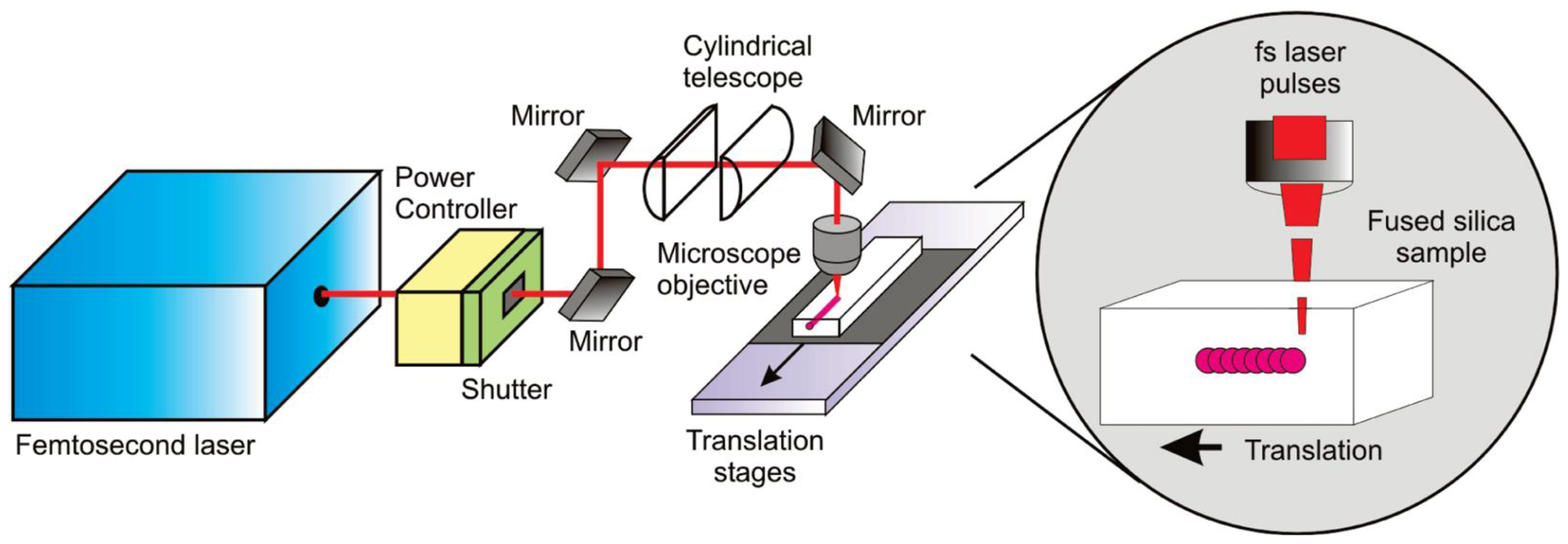
2.1. Femtosecond Laser Irradiation

The substrates used for the microchannel fabrication are 1 × 2 × 6 mm parallelepipeds made of commercial fused silica (Foctek Photonics, China). The experimental setup used for the laser irradiation process is shown in Figure 1 and extensively documented [11,12]; it is based on a femtosecond laser microfabrication apparatus initially described in [13,14]. It starts with a regeneratively amplified Ti:sapphire laser (model CPA-1 from Clark Instrumentation), generating 150 fs, 500 μJ pulses at 1 kHz repetition rate and 790 nm wavelength.
Figure 1. Setup used for femtosecond laser irradiation.
Micromachines 03 00604 g001
For the irradiation it has been used only a fraction of the pulse energy, up to 5 μJ. The beam, initially with circular cross section, is astigmatically shaped by passing it through a cylindrical telescope (f1 = 50 mm, f2 = 150 mm), providing a demagnification by a factor of 3 in one transverse direction. Astigmatic beam shaping allows controlling of the focal volume in such a way that the cross section of the modified track becomes symmetric and with arbitrary size [13]. The astigmatically shaped beam is focused by a 50× microscope objective (numerical aperture 0.6, focal length 4 mm). The writing beam polarization is linear and orthogonal to the translation direction. The samples are moved perpendicularly to the beam propagation direction by a precision translation stage (Physik Instrumente) at a constant speed.

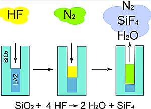
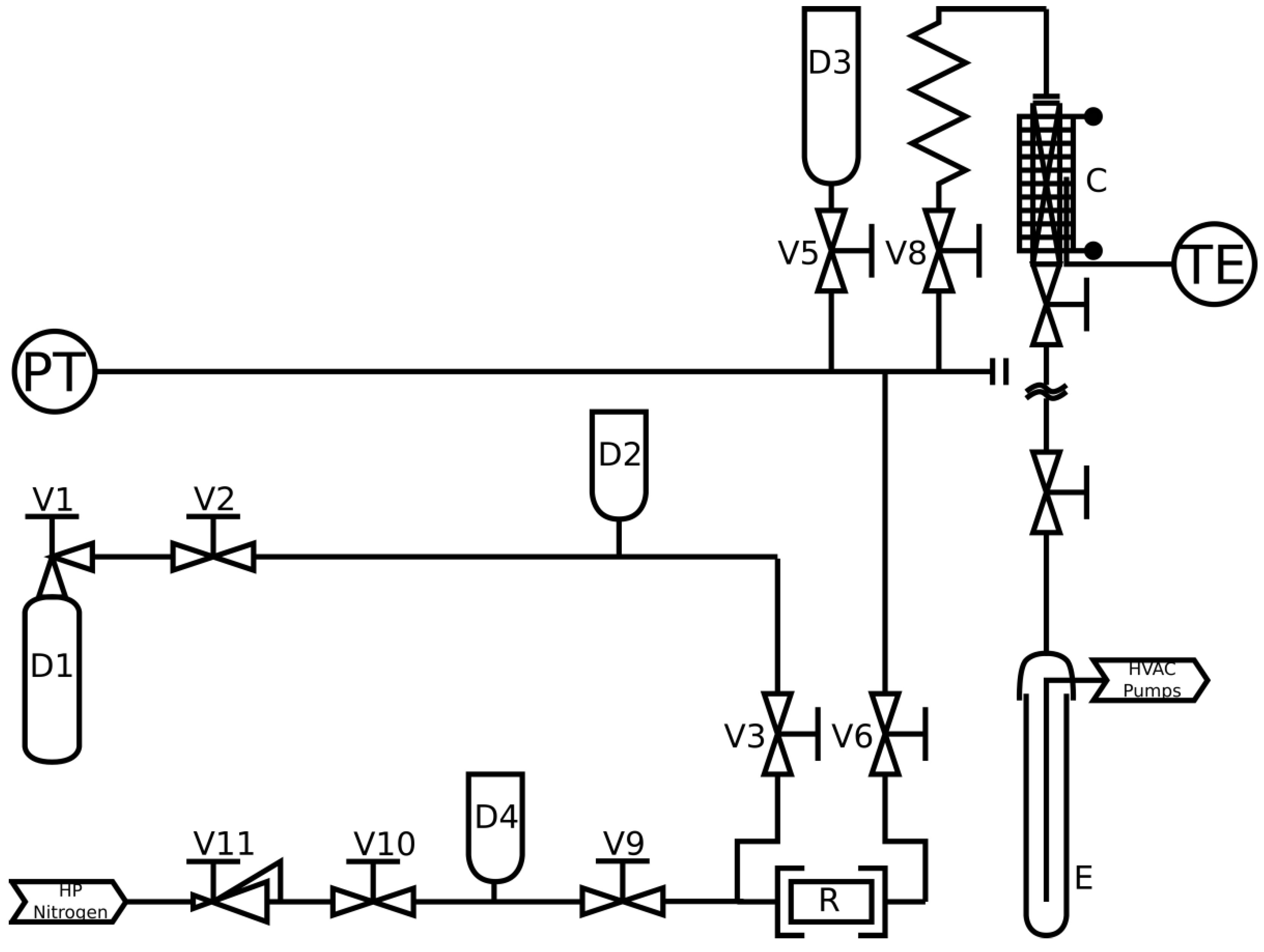
2.2. Gaseous HF Etching

A scheme of the experimental setup used for gaseous HF acid etching is shown in Figure 2. A cylinder containing liquid anhydrous HF (99.5% Rivoira) is connected to the reactor with a vacuum line built with 1/4 in. AISI316 tubing and AISI316 severe service valves (Swagelok JB and JBR), according to the procedures for safety handling of HF described in the literature [15].
Figure 2. Schematic of the etching apparatus. D1: Hydrofluoridric acid cylinder; D2,D3,D4: Expansion drums; V1-V11: valves; R: Etching reactor; C: Heated soda lime trap; E: Cold trap; PT: Pressure transducer; TE: Thermocouple.
Micromachines 03 00604 g002
The reactor has a volume of 52 cm3 and is connected with a stainless steel membrane to a pressure measurement system (Endress+Hauser Cerabar T PMP131). The reactor is also connected through the vacuum line to a knockout trap and a liquid-nitrogen cooled condenser that sequestrates the unreacted acid and moisture, hence protecting the vacuum pumps. The knockout trap is a 2 × 50 cm glass tube limited by two valves and filled with soda lime that contains ethyl violet in order to provide a visual measurement of the soda consumption. The unreacted acid present in the etching gases reacts exothermically with the soda lime. The trap is heated once a day using an electric sheath to 230 °C for 2 h to release most of the absorbed water derived by the reaction of HF with soda lime. This water is frosted in the liquid-nitrogen cooled condenser and subsequently disposed. Vacuum in the reactor (1 × 10⁻⁴ mbar) is provided by the combination of two pumps: a rotative pump (Boc Edwards RV12) and a diffusive pump (Boc Edwards 8,000 L/h). The irradiated fused silica sample is loaded in the reactor and the tube is connected to the vacuum line. Before addition of the HF, the reactor is put under vacuum. Subsequently the selected pressure of room temperature HF is pulled into the reactor using the vacuum line, limited by the two valves (V2, V3) as shown in Figure 2. After the desired reaction time τR = 2 min the reactor is connected to the vacuum line and the unreacted HF, as well as the reaction products, is removed. Subsequently the reactor is reconnected to the HF reservoir (by closing V6 and opening V3), and the cycle is repeated for a given number of times until a 1,200 µm long channel is obtained. A complete cycle thus consists of the combination of two steps: (1) HF-fused silica reaction and (2) products desorption. For all experiments, the desorption time τD has been fixed to 3 min to completely evacuate the reactor. After the desired micro channel length has been obtained, the system is purged with vacuum and subsequently with nitrogen. After this pre-etching a new procedure described below has been applied.

2.3. HF Etching with Dynamic Displacement

The gaseous HF etching procedure described above has been applied to obtain 1,200 µm long michochannels. After the gaseous etching the novel “dynamic displacement” procedure has been applied.
The selected pressure (PR) of room temperature HF is pulled into the reactor using the vacuum line, limited by the two valves (V2, V3). After the desired reaction time, τR , the reactor is connected to the high pressure nitrogen line, limited by the two valves (V9, V10) and left in this status (PN) for a period τN (nitrogen time). After the period τR+τN has passed the reactor is connected to the vacuum line and the unreacted HF, as well as the reaction products, are removed by pumping for a desorption time τD. A complete cycle thus consists of the combination of three steps: τR HF-fused silica reaction time, τN nitrogen induced displacement period and τD products desorption period. After 10 cycles, the system is purged with vacuum and subsequently with nitrogen. The reactor is opened and the geometrical features of the etched channels are measured by using a polarized light microscope (Olympus BX51). For all experiments the desorption time τD has been fixed to 3 min to completely evacuate the reactor while τR and, τN were changed by varying one parameter amongst PR (20; 50; 100; 150 mBar), PN (0; 250; 500 mBar), τR (15; 120 s) and τN (0; 105; 165 s).

3. Results and Discussion

3.1. Gaseous HF Etching

The use of low-pressure gaseous HF etchants and the related comparison between liquid and gas phase etching has been extensively discussed by Venturini et al. [12]. The aspect ratio of the microchannel obtained using the gaseous etching procedure (described in Section 2.2) with τR = 2min and τD = 3 min is shown in Figure 3 and a picture of the starting channel used for the dynamic displacement tests is shown in Figure 4.
The gas phase etching described in Section 2.2 can quickly produce 3 mm long channels with an aspect ratio higher than 25. Unfortunately the aspect ratio is not constant and depends on the length of the channel. It is possible to recognize, in the experimental data shown in Figure 3, the presence of two definite reaction regimes present in the forming channel. In the first reaction regime, at the beginning of the etching process, the aspect ratio increases quickly, while the length of the microchannel grows until it reaches a maximum at around 1,400 µm. After reaching this length a second reaction regime is established and the aspect ratio starts to decrease.
Figure 3. Diameter (Red) and Aspect Ratio (Green) of the sample that undergone the 2 min etching time in Section 2.2.
Micromachines 03 00604 g003
Figure 4. Microchannel with L/D ≈ 25 and L ≈ 1.2 mm obtained following the procedure in Section 2.2 with a 2 min etching time. The image has been taken under polarized light (the channel is black and the irradiated silica is white).
Micromachines 03 00604 g004
At the beginning of the etching process, in the chemical regime region, the excavation velocity is high, but as soon as the channel starts growing the excavation velocity becomes smaller and smaller due to an increase in diffusion resistances distinctive of the diffusive regime region. To demonstrate the existence of a diffusive regime the chemical reaction ratio and the diffusivity of the etchant are compared together in Equation (1) using the Damköhler.
Micromachines 03 00604 i001
where k is the kinetic constant; C is the HF concentration; L is the diffusion length; n is the reaction order and D the Knudsend diffusivity.
This dimensionless quantity is the ratio between the reaction rate and the etchant diffusivity. At low Damköhler numbers (L < 500 µm; Da < 1) the reaction is under chemical regime, while for higher Damköhler values (L > 500 µm; Da > 1) it falls in the diffusive regime. In particular if the Damköhler number is greater than one, the reaction ratio (excavation velocity) is higher than the diffusion speed and the etching reaction is under diffusion regime.
The change in etching regime moving from the external surface (chemical regime) to the internal one (diffusive regime) can be conveniently visualized in Figure 5.
Figure 5. Calculated Damköhler number from the data already reported; k = 4.5 × 10⁴ s−1; n = 1.
Micromachines 03 00604 g005
The chemical etching ratio (k = 4.5 × 10⁴ s−1; n = 1) has been inferred from the experimental data by considering a first order reaction shown in Equation (2).
Micromachines 03 00604 i002
where CHF is the concentration of hydrogen fluoride and nSiO2 represent the moles of silica. It is important to infer the kinetic data at short microchannel lengths to avoid any interference from the diffusive regime. An approximated kinetic constant can be calculated by extrapolating the excavation speed at zero-length (16 µm/min). The ratio of silica consumption (7 × 10⁻³ µmol/min) can be inferred by considering a developing truncated cone, whose volume is growing with a velocity of 137 × 103 µm3/min. For every mole of silica four moles of acid are needed thus the acid depletion speed is 25 × 10−3 µmol/min.
A further important factor to be considered in calculating the Damköhler Number is the diffusivity of the etching agent. Apart from temperature, diffusivity depends on molecular weight and mean free path of the considered molecule. In case of diffusion in microchannels, the molecule is more likely to collide with the walls as opposed to another molecule. A proof of this fact is available in Equation (3) where the mean free path is calculated in the etching conditions.
Micromachines 03 00604 i003
The symbol λ represent the mean free path of a gas evaluated at the etching conditions. R is the gas constant, Na is the Avogadro number, T is the temperature, P is the etchant pressure and σ is the molecular diameter [16].
The higher the molecular weight, the higher the molecular diameter, the lower is the diffusivity. An experimental measurement of the molecular weight has been taken by expanding, up to 20 mBar, a known quantity of hydrogen fluoride in the reaction volume. The pressure has been recorded and the molecular weight has been calculated. The number obtained (MW ≈ 84 g/mol) shows that hydrogen fluoride possesses complex oligomeric structures, also in the etching conditions [17]. These structures accounts for the low diffusivity thus a high Damköhler number.
In these conditions the Diffusivity should be calculated under the hypothesis of Knudsen using Equation (4).
Micromachines 03 00604 i004
where D is the Knudsen Diffusivity, R the gas constant, MW is the molecular weight; r is the radius of the microchannel and T is the temperature.
An increase in hydrogen fluoride pressure results in an increase of molecular weight (MW) and σ thus in a decrease in diffusivity. However, when the governing etching mechanism is driven by the chemical reaction, i.e. in short channels, an increase in HF pressure results in a growing etching speed. When the etching is governed by diffusion, like in deep microchannels, an increase in HF pressure results in a decrease in diffusivity and thus in a reduced reaction ratio.
Experimentally, at low channel length, pressures of HF above 130 mBars led to high etching speed but strongly conical shaped channels. The shape of the microchannels obtained suggests that the reaction at high pressure is diffusion driven. At low HF pressure (10–50 mBars) the reaction produces high aspect ratio microchannels at a lower speed, thus indicating that the diffusion is not interfering with the etching mechanism.

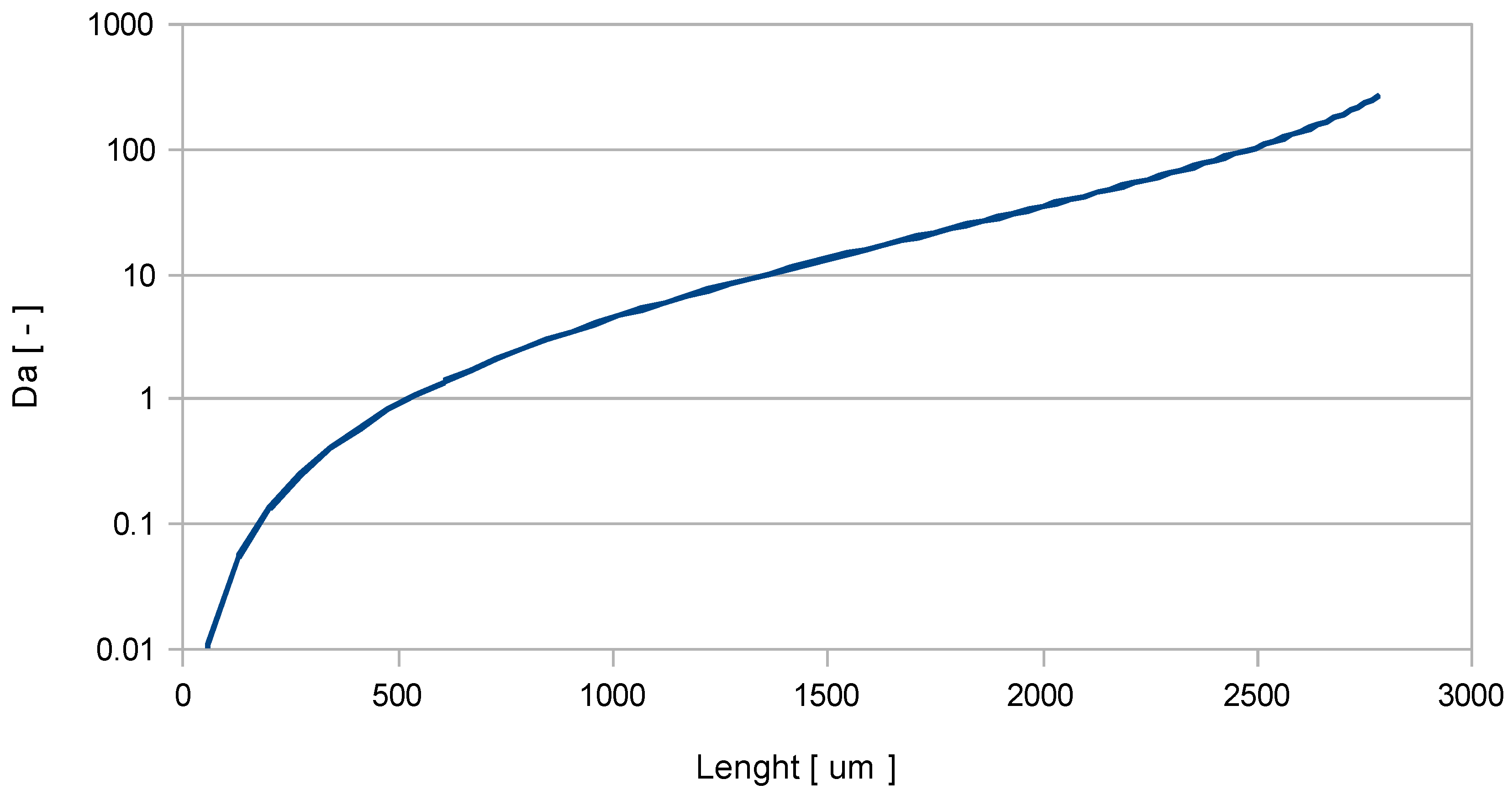
3.2. HF Etching with Dynamic Displacement
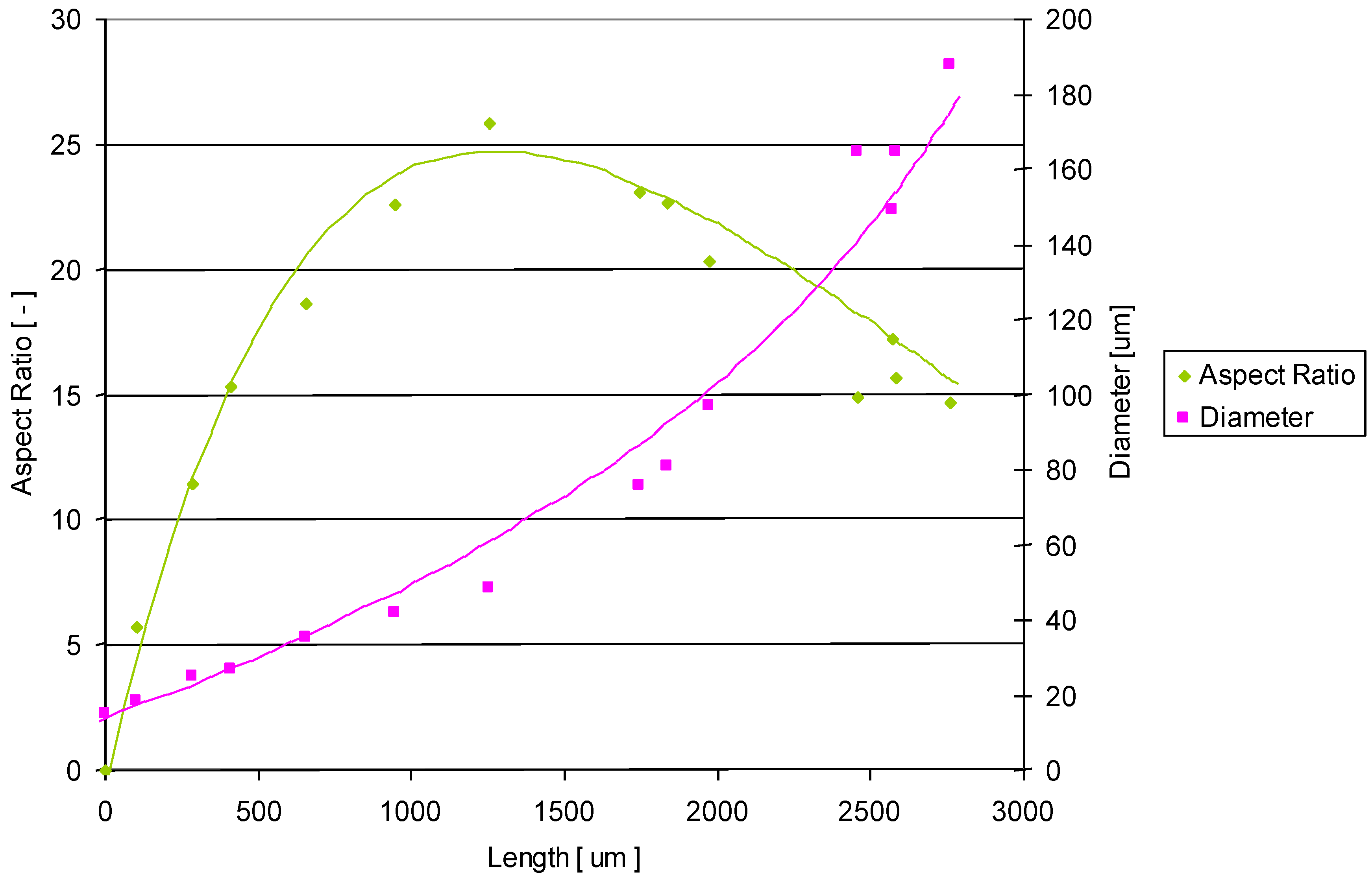
The procedure that has been set up has the aim of constraining the hydrogen fluoride on the bottom of an already made channel (shown in Figure 4) thus preventing it to react with the walls. It has been realized by introducing a high pressure of inert gas immediately after the etching gas.
Initially it consists in vacumizing the reactor containing the irradiated glass sample to be etched and then applying a certain pressure (PR) of gaseous HF and holding this pressure for a known period of time (τR). In this first step the channel is filled with HF. Immediately following this step the gaseous HF is displaced at the bottom of the forming channel by introducing nitrogen at high pressure (PN) in the etching reactor. The system is left to react for a certain time (τN) after which the gases are removed by vacuum. The procedure is repeated iteratively.
The influence of the process parameters on the etching speed as well as on microchannels aspect ratio has been analyzed by using the Pearson product-moment correlation on the data in Table 1 between inputs and outputs shown in Equation (5).
Micromachines 03 00604 i005
Table 1. Results obtained.
(τR) Reaction Time [s](PR) HF Pressure [mBar](τN) Nitrogen Time [s](PN) Nitrogen Pressure [mBar]Etching Speed [µm/min]Aspect Ratio [L/D]
112020009.114.7
2151501055006.714.9
3151001055005.418.1
415501055004.821.4
512020009.322.7
6151501055005.023.0
7151501655002.525.9
8151001055009.025.1
915501055004.328.6
1015201055006.328.7
1115201655004.227.4
1215201652504.123.1
13120200013.025.8
The space of variables is generated by four inputs: HF pressure (PR), reaction time (τR), dilution pressure (PN), dilution time (τN) and two outputs: etching speed and aspect ratio. It should be noted that the Pearson correlation coefficient is a simple but not comprehensive, method to analyze the data.
By analyzing the results, shown in Figure 6 it can be inferred that an increase in HF pressure results in a slight decrease in speed and selectivity but these data do not appear strongly correlated. This is the opposite of what was inferred in the preliminary tests thus it is a symptom that the correlations are nonlinear. An increase in the etching speed could be achieved by lowering the nitrogen pressure and the dilution time or by increasing the reaction time.
Figure 6. Correlation coefficients for speed and aspect ratio in the experiments performed.
Micromachines 03 00604 g006
An interesting reverse interpretation of the results shown in Figure 6 suggest that there is the possibility of increasing the aspect ratio by correctly acting on the dynamic displacement parameters, in particular by reducing the high etching speed (10 µm/min). When this methodology is applied to activated silica, a propagating pressure shock-wave was able to wash the external sample surface and force the HF to move to the bottom of the channel. Thus an increase in selectivity has been achieved as shown in Figure 7 by applying the procedure with the following parameters: PR = 50 mBar, PN = 500 mBar, τR = 15 s, τN = 2 min. The etching speed was 4 µm/min which is lower than the one observed in the standard procedure (12 µm/min).
Figure 7. Photo of microchannel obtained applying 20 steps of dynamic displacement method Length ≈ 1.4 mm; aspect ratio ≈ 29. The parameters used for the etching are: PR = 50 mBar, PN = 500 mBar, τR = 15 s, τN = 165 s The black bubble inside the channel is air while the white part is filled with water.
Micromachines 03 00604 g007

4. Conclusions

The dynamic displacement method herein presented resulted in a 13% increase in the aspect ratio at the expense of a decrease in the etching speed. This approach allowed us to quickly obtain etched channels with an unprecedented aspect ratio for HF etching of fused silica.
The obtained aspect ratio (L/D = 29) is, to our knowledge, the best result obtained up to now for the gaseous HF etching. In contrast, the observed etching speed of 4 µm/min is lower compared to the observed etching speed adopting the standard low pressure HF etching procedure. However more studies are needed to understand the maximum length achievable.
Compared to the standard methodologies, this technique does not require a “clean room” while having the potential to replace, in some applications, the photo-lithographic approach and the use of photo-sensitive glass like FOTURAN.

References

  1. Navarrini, W.; Venturini, F.; Tortelli, V.; Basak, S.; Pimparkar, K.P.; Adamo, A.; Jensen, K.F. Direct fluorination of carbon monoxide in microreactors. J. Fluorine Chem. 2012, 142, 19–23. [Google Scholar] [CrossRef]
  2. Madou, M.J. Manufacturing techniques for microfabrication and nanotechnology. In Fundamentals of Microfabrication and Nanotechnology, 3rd ed; CRC Press: Boca Raton, Florida, USA, 2011; Volume 2. [Google Scholar]
  3. Sansotera, M.; Navarrini, W.; Resnati, G.; Metrangolo, P.; Famulari, A.; Bianchi, C.L.; Guarda, P.A. Preparation and characterization of superhydrophobic conductive fluorinated carbon blacks. Carbon 2010, 48, 4382–4390. [Google Scholar] [CrossRef]
  4. Marco, C.D.; Eaton, S.M.; Suriano, R.; Turri, S.; Levi, M.; Ramponi, R.; Cerullo, G.; Osellame, R. Surface properties of femtosecond laser ablated PMMA. ACS Appl. Mater. Interfaces 2010, 2, 2377–2384. [Google Scholar] [CrossRef]
  5. Gattass, R.R.; Mazur, E. Femtosecond laser micromachining in transparent materials. Nat. Photonics 2008, 2, 219–225. [Google Scholar] [CrossRef]
  6. Khan Malek, C.G. Laser processing for bio-microfluidics applications (part I). Anal. Bioanal. Chem. 2006, 385, 1351–1361. [Google Scholar] [CrossRef]
  7. Khan Malek, C.G. Laser processing for bio-microfluidics applications (part II). Anal. Bioanal. Chem. 2006, 385, 1362–1369. [Google Scholar] [CrossRef]
  8. Marcinkevicius, A.; Juodkazis, S.; Watanabe, M.; Miwa, M.; Matsuo, S.; Misawa, H.; Nishii, J. Femtosecond laser-assisted three-dimensional microfabrication in silica. Opt. lett. 2001, 26, 277–279. [Google Scholar] [CrossRef]
  9. Maselli, V.; Osellame, R.; Cerullo, G.; Ramponi, R.; Laporta, P.; Magagnin, L.; Cavallotti, P.L. Fabrication of long microchannels with circular cross section using astigmatically shaped femtosecond laser pulses and chemical etching. Appl. Phys. Lett. 2006, 88, 191107:1–191107:3. [Google Scholar]
  10. Osellame, R.; Maselli, V.; Vazquez, R. M.; Ramponi, R.; Cerullo, G. Integration of optical waveguides and microfluidic channels both fabricated by femtosecond laser irradiation. Appl. Phys. Lett. 2007, 90, 231118:1–231118:3. [Google Scholar]
  11. Kiyama, S.; Matsuo, S.; Hashimoto, S.; Morihira, Y. Examination of etching agent and etching mechanism on femotosecond laser microfabrication of channels inside vitreous silica substrates. J. Phys. Chem. C 2009, 113, 11560–11566. [Google Scholar]
  12. Venturini, F.; Navarrini, W.; Resnati, G.; Metrangolo, P.; Vazquez, R. M.; Osellame, R.; Cerullo, G. Selective iterative etching of fused silica with gaseous hydrofluoric acid. J. Phys. Chem. C 2010, 114, 18712–18716. [Google Scholar]
  13. Osellame, R.; Taccheo, S.; Marangoni, M.; Ramponi, R. Femtosecond writing of active optical waveguides with astigmatically shaped beams. JOSA B 2003, 20, 1559–1567. [Google Scholar] [CrossRef]
  14. Hnatovsky, C.; Taylor, R.S.; Simova, E.; Rajeev, P.P.; Rayner, D.M.; Bhardwaj, V.R.; Corkum, P.B. Fabrication of microchannels in glass using focused femtosecond laser radiation and selective chemical etching. Appl. Phys. A 2006, 84, 47–61. [Google Scholar] [CrossRef]
  15. Walters, D.B. Safe Handling of Chemical Carcinogens, Mutagens, Teratogens, and Highly Toxic Substances; Ann Arbor Science Publishers: Ann Arbor, Michigan USA, 1980; Volume 1. [Google Scholar]
  16. Perry’s Chemical Engineers’ Handbook, 7th ed; McGraw-Hill Professional: New York, USA, 1997.
  17. Redington, R.L. Infrared absorbance of hydrogen fluoride oligomers. J. Phys. Chem. 1982, 86, 561–563. [Google Scholar] [CrossRef]

