Article

Microbeads for Sampling and Mixing in a Complex Sample

1
Institute for Bioengineering and Bioscience, Georgia Institute of Technology, Atlanta, GA 30332, USA
2
School of Mechanical Engineering, Georgia Institute of Technology, Atlanta, GA 30332, USA
3
Center for Food Safety, Department of Food Science & Technology, University of Georgia, Griffin, GA 30223, USA
*
Author to whom correspondence should be addressed.
Micromachines 2013, 4(1), 103-115; https://doi.org/10.3390/mi4010103
Submission received: 21 January 2013 / Revised: 4 March 2013 / Accepted: 5 March 2013 / Published: 19 March 2013

Abstract

:
This paper presents work on the development of a microfluidic device using super-paramagnetic beads for sampling and mixing. The beads are manipulated via an external rotating permanent magnet in a microfluidic channel. Efficient mixing is achieved in a short distance with this method. Modeling shows the variables which influence the mixing are flow rate, bead rotation speed and the bead number density. Displacement of the bead relative the rotating magnetic field sets an upper limit on the bead rotation speed due to viscous drag. Future work will examine optimization of this system for capture of pathogens from a complex mixture.

1. Introduction

Detection of low concentrations of bacteria, viral particles and parasites in food samples is a challenging process [1]. The separation of the target from the food matrix is a key step that needs to be carried out with highly specific capture of the target onto a mobile phase. This can subsequently be separated and concentrated for detection with florescent, electrochemical or quantum dot labeling. The capture of the target can be more effectively carried out with efficient mixing.
Microfluidics provides exciting possibilities for miniaturized biosensors allowing for highly parallel and high throughput tests to be performed in miniaturized “lab-on-a-chip” packaging with a great deal of control utilizing the low Reynolds number flows. However, laminar flow makes mixing of fluid difficult [2]. Passive mixers stretch and fold fluids, shortening diffusion lengths or use herring-bone features in a channel to achieve mixing [2]. These mixers require either complicated 3-D fabrication, relatively long mixing lengths or both. Active mixers exert time-dependent disturbances.
Microfabricated magnetic devices have been made for a variety of manipulation of paramagnetic beads based on the principle of magnetophoresis (MAP). For example, microscale core/coil design [3], current-carrying wires [4], wire matrix [5], and micropatterned conductors [6] have been used for trapping, transport, and catch-and-release of magnetic beads. However, micro-electromagnetic systems are limited to manipulation of small numbers of beads and with low magnetic forces due to Joule heating and complexity concerns.
We present a simple magnetophoresis system capable of controlled transport of rotating paramagnetic beads among soft magnetic patterns. Low aspect ratio super-paramagnetic NiFe discs (250 nm tall, diameter 3 µm) are patterned onto a silicon wafer. A PDMS channel is bonded onto the wafer to create the microfluidic channel. An external permanent magnet attached to a motor provides a magnetic field, which can be rotated at different speeds while magnetizing the NiFe disks in the channel. Paramagnetic microbeads (Dynabeads MyOne® & M-280, Life Technologies, formerly Invitrogen, Carlsbad, CA, USA) introduced into the channel with a syringe pump are trapped at the poles of the now magnetized soft magnetic discs. Rotation of the external permanent magnet will also rotate the induced magnetic poles in the soft magnetic discs which will in turn rotate the trapped microbeads (Figure 1).
Figure 1. Magnetic attraction between paramagnetic beads and induced magnetic poles. As the external permanent magnet rotates, the induced poles within the soft magnetic features also rotate, pulling the magnetic microbead.
Micromachines 04 00103 g001

2. Experimental Section

2.1. Computational Modeling

We use a mesoscale computational method for fluid-structure interactions [7,8,9] to model the dynamics of superparamagnetic beads driven by an external rotating magnetic field in a fluid-filled microchannel. Specifically, our model, which is based on the lattice Boltzmann model (LBM), explicitly captures the interactions among superparamagnetic beads, soft ferromagnetic (NiFe) disks, and a viscous incompressible fluid in a microfluidic channel.
LBM is a lattice-based numerical method for simulating hydrodynamic flows governed by Navier-Stokes equations. The method is based on the time integration of discretized Boltzmann equation for single particle distribution function [10,11]. In our 3D simulation, LBM is characterized by a set of 19 distribution functions, fі (r,t), describing the mass density of fluid particles at a lattice node r and time t propagating in the direction i with a constant velocity cі. The hydrodynamic quantities are calculated as moments of the distribution function, i.e., the density,
Micromachines 04 00103 i001
the momentum,
Micromachines 04 00103 i002
and the momentum flux
Micromachines 04 00103 i003
In order to model fluid mixing in microchannel with magnetic beads, we use a binary LBM, in which second distribution function is introduced to describe behavior of binary mixtures. In this scenario, the system is characterized by two parameters, the mass density distribution
Micromachines 04 00103 i004
and the density difference
Micromachines 04 00103 i005
where fA (r, cі, t), fB (r, cі, t) are the mass density of fluid A and fluid B respectively [12,13,14]. The conserved quantities are calculated as moments of the distribution functions, i.e., the mass density,
Micromachines 04 00103 i006
the momentum,
Micromachines 04 00103 i007
and the order parameter,
Micromachines 04 00103 i008
The time evolutions of these two distribution functions are governed by the single relaxation time lattice Boltzmann equations for ρі (r, t) and ϕі (r, t), that describe the relaxation of distribution functions towards their equilibrium values, ρіeq (r, t) and ϕіeq (r, t) respectively. The equilibrium distributions, which are constructed to conserve mass, momentum, and order parameter, are respectively given by
Micromachines 04 00103 i009
and
Micromachines 04 00103 i010
Here, P is the pressure tensor, u is the macroscopic fluid velocity, μ is the chemical potential, and Г is a coefficient related to the mobility
Micromachines 04 00103 i011
Solid magnetic beads and static discs are modeled using an array of nodes uniformly distributed on the solid surfaces. The nodes are connected by rigid bonds that form triangles representing the solid-fluid interface at which we impose a no penetration and no slip boundary condition [8,15]. The dynamics of magnetic beads is calculated by integrating the Newton’s equation of motion for the nodes
Micromachines 04 00103 i012
using the velocity Verlet algorithm. Here, the total force F(rі) acting on the node at position rі includes the magnetic force and the force exerted by the fluid at the fluid-solid interface. We have previously validated our model in the limit of low Reynolds number and used it to examine microchannel flows with rigid and compliant particles [16,17,18,19,20].
Soft magnetic materials are characterized by a high permeability and a low coercivity, which makes them easy to magnetize and demagnetize. Thus, the magnetization of NiFe disks is saturated readily under the external magnetic field and follows the rotation of external field. Furthermore, the magnetic moments of superparamagnetic beads tend to align along the applied field. Their saturation value is much smaller than the magnetization of NiFe disks, so we consider the influence of beads on the magnetic field to be negligible. The magnetic field of single cylindrical soft magnet can be calculated theoretically [21]. Due the linearity of the magnetic field, we use superposition of the contribution of the disk array to calculate the total magnetic field in the channel [22]. The magnetic force acting on the magnetic beads is
Micromachines 04 00103 i013
where Micromachines 04 00103 i014 is the permeability of free space, B is the magnetic field vector, and
Micromachines 04 00103 i015
is the magnetic moment of bead with Vp being the bead volume and χ being the difference of magnetic susceptibility between beads and the medium. In the case of bead magnetization saturation, the magnetic force simplifies to Equation (15) [23].
Micromachines 04 00103 i016
Our computational setup is shown in Figure 2 with periodic boundary in x direction. The box dimensions are H = 2a, W = 13a, where a is the diameter of bead. We choose disk diameter Dd = a, disk height h = 0.05a, and the spacing s between disks varies from 2a to 1.5a. All these dimensions match experimental measurement.
Figure 2. Computational setup of magnetic mixer.
Micromachines 04 00103 g002

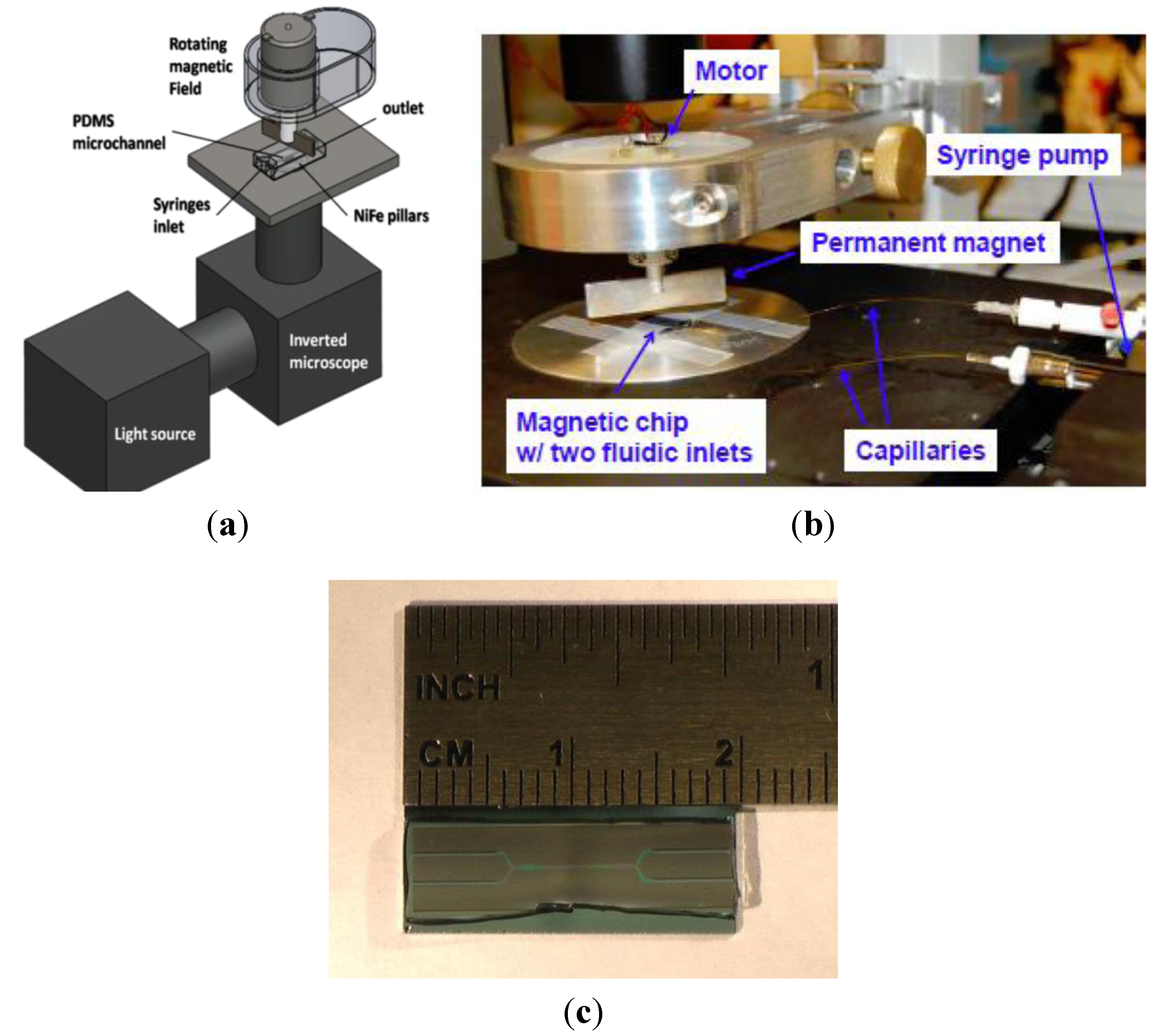
2.2. Current Device Fabrication and Characterization

2.2.1. PDMS Molding

Polydimethylsiloxane microfluidic channels are created by making a 10:1 mixture of Sylgard 184 Elastomer Base and Sylgard 184 Elastomer Curing agent. This mixture was manually stirred for 5 min and then degased until all visible air bubbles were removed. The degased mixture is poured over a SU-8 mold slowly to prevent air bubbles from becoming trapped in the mixture. The mold and uncured PDMS mixture is placed in an oven at 80 °C for 1 hour for curing. After curing, the PDMS array of microfluidic channels is peeled from the mold and stored in a wafer box for future use. Current channel dimensions have a height of 6.5 microns and a width varying from chip to chip of 100 to 175 microns wide.

2.2.2 Chip Fabrication

Full detail for chip fabrication has been previously described [24,25]. In summary, photoresist is patterned on to a “100” silicon wafer. A 10 nm Ti adhesion layer is evaporated onto the chip. Next, a 250 nm of a NiFe alloy is evaporated onto the wafer and photoresist to create the magnetic features. The photoresist is then lifted off in acetone, before growing a 125 nm layer of SiO2 via plasma enhanced chemical vapor deposition. This process must be done via this technique, because PECVD temperatures are low enough to not oxidize the Fe in the magnetic features. The final SiO2 layer is important because it protects the NiFe magnetic features from oxidation in the device and allows the magnetic features’ surface to be functionalized. The SiO2 layer is then annealed before a final layer of photoresist is placed over the entire wafer to protect the wafer surface during dicing to create individual chips.

2.2.3. Chip Preparation

For chip preparation, chips are rinsed twice with acetone in a glass beaker to remove the photoresist. During each rinse, the beaker containing chips and acetone is gently agitated for 30 s. Chips are then washed with ethanol twice to remove any remaining acetone.
Chips are then sonicated three times, for twenty minutes each, in ethanol, 0.5 M KOH and ethanol at room temperature. After each sonication, the chips are rinsed with DI water for a few seconds. The chips are then rinsed twice with isopropanol and then sonicated for 15 min in a silanization solution (49.5 mL isopropanol, 3 microliters glacial acetic acid and 0.5 mL of (3-aminopropyl)triethoxysilane). After silanization, the chips are washed twice in isopropanol then dried in an oven at 90 °C for 30 min.

2.2.4. Device Assembly

The PDMS microfluidic channel described in the PDMS molding section of this paper and the chip with the NiFe magnetic features are placed into separate 2 mL conical tubes with ethanol. The tubes are then sonicated for 5 min. The PDMS channel is placed onto the chip, aligning the PDMS channels over the magnetic features. This alignment is done by hand using forceps under an upright microscope at 20× magnification. The assembled device is then covered while the ethanol is allowed to evaporate from the chip to atmosphere. Once dry, silica tubing (180 microns outer diameter, 100 microns inner diameter) is inserted into the inlets of the device and sealed with uncured PDMS. The inlets for the tubing are created during the PDMS molding process. The inlets are patterned as 250 micron wide and 250 micron tall channels that are open to the sides of the device. This side access for tubing is required because the magnetic features are patterned on to an opaque silicon wafer and an inverted microscope is needed for imaging during experiments. The traditional method of punching port holes into the top of the PDMS cannot be used because the device is flipped with the PDMS layer resting on the inverted microscope stage. After sealing, the entire device is placed on an 80 °C hot plate to cure the sealing PDMS.

2.2.5. Magnetic Bead Solution

Streptavidin coated Dynabeads M-280, 2.8 micron in diameter, were obtained from Life Technologies, formerly Invitrogen. For use in experiments, the stock solution of beads is diluted by a factor of 20 in reagent-grade water with 0.1% Tween-20.

2.2.6. Magnet and Motor Assembly

A custom aluminum and Delrin fixture is used to suspend a Mabuchi RE-260-2295 DC motor over the stage of a Nikon Eclipse inverted microscope. This fixture allows for x, y, and z positioning of the magnet. Note that non-magnetic materials were used whenever possible so as not to interfere with the magnetic field. A permanent bar magnet (B-882-N52, from K&J Magnetics, Jamison, PA, USA) is affixed to the motor shaft via a custom aluminum fixture, at a defined distance above the microflow channel. Figure 3 shows images of our experimental set-up, including microscope, magnet and motor assembly as well as an image of the assembled PDMS microchannel and chip.
Figure 3. Images of experimental set-up. Bottom image shows assembled PDMS channel with two inlets and two outlets and chip with NiFe features.
Micromachines 04 00103 g003

3. Results and Discussion

3.1. Computational Modeling of Mixing

We first examine the mixing performance without fluid flow. We define a dimensionless parameter mixing degree
Micromachines 04 00103 i017
to characterize the efficiency of mixing, where ϕ is the concentration of fluid. When σ equals 1, it means two fluids are fully separated. When it equals 0, it means fully mixed. In Figure 4a, we show the mixing profile due to pure diffusion in the microchannel. Figure 4b shows snapshots of concentration profiles for different magnetic mixer configurations. In the figure, the black circle denotes the disk and the green circle denotes the magnetic bead. We find that the rotation of beads stretch the interface between two fluids, thus enhancing mixing significantly. We also find the mixing is enhanced as the spacing between disks decreases.
Figure 4. Comparison of mixing efficiency between pure diffusion (a) and magnetic mixer without channel flow after 100 bead revolutions (b). The concentration is averaged over channel height. The back circles denote the position of static discs, whereas the green circles indicate the instant position of rotating beads. In (b), left, 2 beads rotation per disk with 2a spacing; middle, 1 bead per disk with 2a spacing; right, 1 bead per disk with 1.5a spacing.
Micromachines 04 00103 g004
Next, we examine the effect of the channel flow rate on mixing performance. We keep the same rotation speed and configuration (1 bead rotation per disk with 1.5a spacing) and vary flow rate. In Figure 5, we show how fluid mixing changes with number of bead rotation periods. We find that an increase in channel flow ratereduces the mixing performance of rotating magnetic beads. Our simulations show that the flow tends to flatten the interface the fluids, thus suppressing the mixing. Thus in order to obtain better mixing performance, one needs to increase the relative rotation speed of beads.
Figure 5. Mixing degree versus time for different flow rates (Um is the maximum velocity of channel flow, Vb denotes the rotation velocity of beads).
Micromachines 04 00103 g005

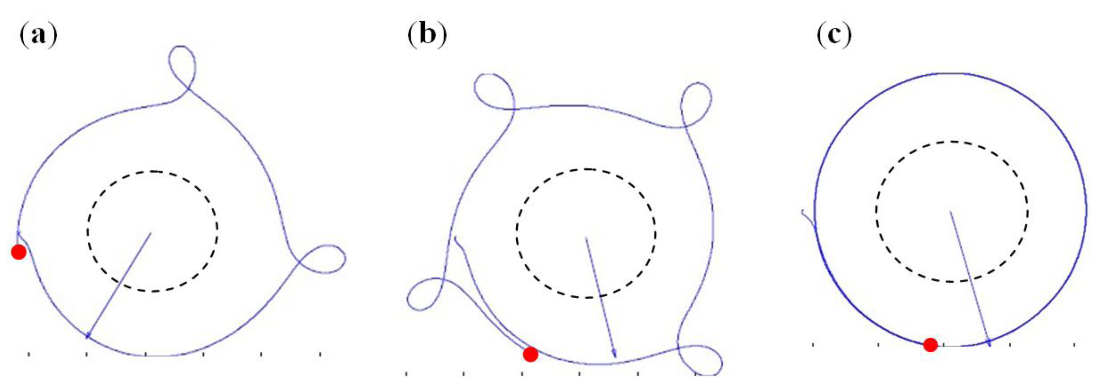
3.1.1. Bead Trajectories

Our simulations indicate that spatial trajectories of beads strongly depend on the magnitude of the magnetic field and its rotation frequency. When the magnetic field strength is low or/and frequency is high beads exhibit aperiodic motion. Illustrative examples of such motion are shown in Figure 6.
Figure 6. Trajectories of magnetic beads moving around static disks in a rotating magnetic field. (a) A bead completes one period around the disk during about three periods of the magnetic field (f = 8000 RPM, B = 0.063 T). (b) A bead completes one period around the disk during about four periods of the magnetic field (f = 10,000 RPM, B = 0.074 T). (c) A bead rotates with the frequency equal to that of the external magnetic field and follows nearly circular trajectory around the disk (f = 8000 RPM, B = 0.13 T). The dotted line shows the outer contour of the static disk. The dot indicates the final position of the bead, whereas the arrow shows the direction of magnetic field.
Micromachines 04 00103 g006

3.2. Experimental Device Characterization

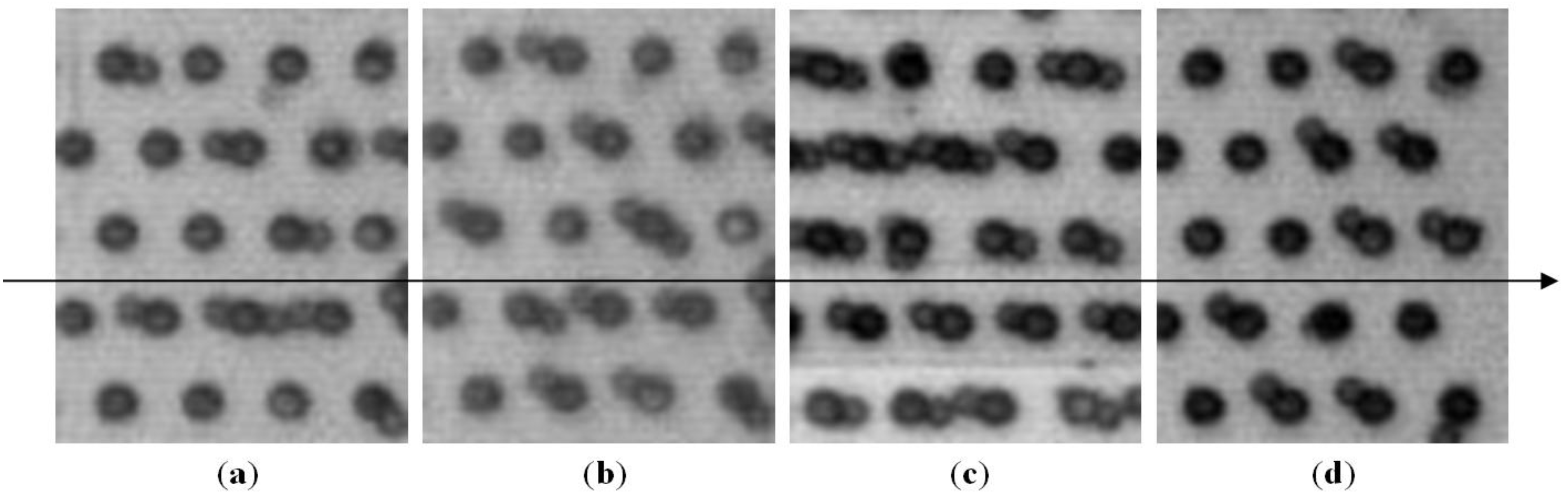
3.2.1. Dynamics of High Speed Rotation

Our theoretical model shows that there is a phase lag between the direction of magnetic field and the direction to the rotating bead (Figure 7c). This phase difference increases with increasing rotating speed or decreasing magnetic strength. The lag increase will progress until the beads no longer maintain the same frequency as the magnetic field lines (Figure 7a,b). Because the phase angle lag is due to the fluid drag force acting on the bead, the phase angle lag can be used as an indirect measure of drag force on the bead.
To examine the operating conditions of the experimental device, the phase lag was measured using two linked high speed Phantom cameras (cameras used: v210 and v9.0, Vision Research, Wayne, NJ, USA). One camera was used to image the spinning and the second camera imaged the beads rotating in the device. Knowing the position of the magnet, gives the direction of the magnetic field.
Figure 7 shows images of beads in the device rotating at two different speeds with two different magnetic field strengths. In each image, the magnetic field lines are horizontal. We find a noticeable variance in the phase angle experienced by beads in the same image. We relate this variation in phase between different beads to slightly different hydrodynamic interactions arising among neighboring beads when the lattice is not fully populated. Another possibility is that beads alternate between periods of sliding or rolling when they move along the silicon surface resulting in unsteady hydrodynamic resistance on individual beads.
Figure 7. Images of microbead circling around static discs in rotating magnetic field. The alignment of the magnetic field lines is represented by the arrow through the images. The magnetic field rotational speed and magnetic field strength felt at the chip is given beneath the images. These were the two experimental parameters varied for the experiments. (a) Speed: 2500 rpm, Mag. Field: 0188 T; (b) Speed: 10,000 rpm, Mag. Field: 0.18 T; (c) Speed: 2500 rpm, Mag. Field: 0.088 T; (d) Speed: 10,000 rpm, Mag. Field: 0.088T.
Micromachines 04 00103 g007
To quantify the phase lag, the angle between the magnetic field and the bead direction was measured at four different speeds. Figure 8 summarizes the results from these measurements, where each data point represents measurements of 60 beads taken across 6 different time points.
These experiments lead to two important observations. First, phase angle lag appears to be inversely related to the magnetic field strength at the chip. It is expected that a weaker magnetic field at the chip more weakly magnetizes the NiFe pillars. This in turn yields a weaker magnetic force pulling the microbeads towards the pillars. As the magnetic force weakens, the drag force causes the microbead to lag more.
Figure 8. Experimental and simulated (use the model described previously) phase angle lags for four different magnetic field rotational speed and two different magnetic field strengths. The force plotted here is the horizontal component of the magnetic force which is balanced by the viscous drag force. Each experimental data point represents 60 measurements across 6 time points. Error bars represent one standard deviation.
Micromachines 04 00103 g008
Figure 8 shows that the experimental and simulation phase angle lag exhibits nearly a linear relationship with magnetic field rotation speed. It was verified using a high speed camera that the bead in Figure 8 maintained synchronicity with the rotating magnetic field. Thus magnetic field rotation speed can be used as an analog for bead linear velocity. Taking this and the phase angle lag as an indirect measure for drag force, the rotating microbeads appear to be following Stoke’s law,
Micromachines 04 00103 i018
which states that for low Re number flows, the drag force on a spherical particle is linearly related to the velocity of the particle. It is possible the discrepancies between the model and experimental values could be from an unaccounted for traction force between the chip surface and the bead or potentially a discrepancy in the modeled value of the magnetization constant of the NiFe pillars in simulation.

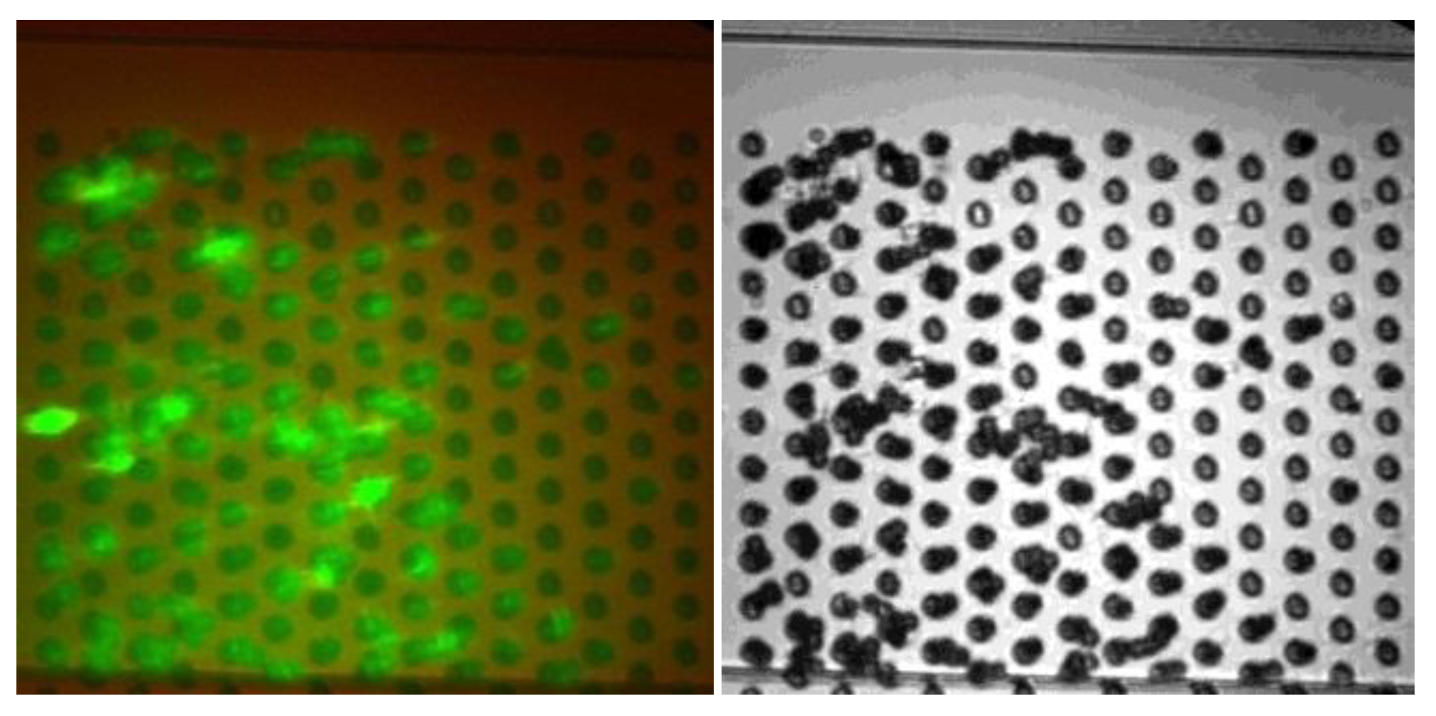
3.2.2. Microbeads Capture Capacity

In order to quantify the amount of material capture on the rotating beads, we injected fluorescent nanospheres (Fluosphere, 40 nm diameter, from Life Technologies, formerly Invitrogen, Carlsbad, CA, USA) labeled with biotin which bind to streptavidin coated M-280 beads (2.8 micron diameter). The nanospheres, suspended in a 0.5% solution by volume in PBS + 0.1% Tween-20, were introduced into the channel at a linear velocity of 0.19 mm/s for 5 min. Figure 9 shows that rapid capture has taken place at the surface of the beads.
Figure 9. Capturing performance of rotating magnetic beads. The fluorescence in the image is the presence of biotin-labeled Fluospheres (Invitrogen) bound to the M-280 microbeads after the flow. The image on the right is the brightfield image showing the positions of the M-280 microbeads.
Micromachines 04 00103 g009

4. Conclusion and Future Work

Efficient mixing is achieved in a short distance with the paramagnetic beads. Modeling shows the variables which influence the mixing are flow rate, bead rotation speed and the number of beads in the channel. Displacement of the bead relative the rotating magnetic field sets an upper limit on the bead rotation speed. We have demonstrated the fast capture of fluorescent nanospheres on the beads. Future work will investigate the effects of device geometry by optimizing the flow rate and bead rotation speed in order to capture particles of different sizes efficiently from a complex mixture. The long term objective of this work is to develop a practical compact portable pre-concentration and pathogen purification system for complex mixtures important for food and environmental safety that can be applied to a wide range of assays.

Acknowledgments

Thanks to Zhengchun Peng for the early stage work in developing this device. Many thanks to Ricardo Aguilar and Elena Cox for fabrication of the NiFe features on the silicon chips used in these experiments. Thanks to the staff at the Nanotechnology Research Center at Georgia Tech for their technical support, and to David Hu and Todd Sulchek, for loan of the high speed cameras. Financial support from the NSF CBET grant is also acknowledged.

References

  1. Dwivedi, H.P.; Jaykus, L.A. Detection of pathogens in foods: The current state-of-the-art and future directions. Crit. Rev. Microbiol. 2011, 37, 40–63. [Google Scholar] [CrossRef]
  2. Suh, Y.K.; Kang, S. A review on mixing in microfluidics. Micromachines 2010, 1, 82–111. [Google Scholar] [CrossRef]
  3. Ramadan, Q.; Samper, V.; Poenar, D.; Yu, C. Magnetic-based microfluidic platform for biomolecular separation. Biomed. Devices 2006, 8, 151–158. [Google Scholar]
  4. Deng, T.; Whitesides, G.M. Manipulation of magnetic microbeads in suspension using micromagnetic systems fabricated with soft lithography. Appl. Phys. Lett. 2001, 78, 1775–1777. [Google Scholar] [CrossRef]
  5. Lee, H.; Purdon, A.M.; Chu, V.; Westervelt, R.M. Controlled assembly of magnetic nanoparticles from magnetotactic bacteria using microelectromagntes arrays. Nano Lett. 2004, 4, 995–998. [Google Scholar] [CrossRef]
  6. Wirix-Speetjens, R.; de Boeck, J. On-chip magnetic particle transport by alternating magnetic field gradients. IEEE Trans. Magn. 2004, 40, 1944–1946. [Google Scholar] [CrossRef]
  7. Mao, W.; Peng, Z.; Hesketh, P.J.; Alexeev, A. Microfluidic mixing using an array of superparamagnetic beads. In Proceedings of the American Physical Society Meeting, Dallas, TX, USA, 21 March 2011.
  8. Alexeev, A.; Verberg, R.; Balzas, A.C. Modeling the motion of microcapsules on compliant polymeric surfaces. Macromolecules 2005, 38, 10244–10260. [Google Scholar] [CrossRef]
  9. Alexeev, A.; Verberg, R.; Balazs, A.C. Designing compliant substrates to regulate the motion of vesicles. Phys. Rev. Lett. 2006, 96. [Google Scholar] [CrossRef]
  10. Succi, S. The Lattice Boltzmann Equation for Fluids Dynamics and Beyond; Clarendon Press: Oxford, UK, 2001. [Google Scholar]
  11. Ladd, A.J.C.; Verberg, R. Lattice-Boltzmann simulations of particle-fluid suspensions. J. Stat. Phys. 2001, 104, 1191–1251. [Google Scholar] [CrossRef]
  12. Verberg, R.; Pooley, C.; Yeomans, J.; Balzas, A. Pattern formation in binary fluids confined between rough, chemically heterogeneous surfaces. Phys. Rev. Lett. 2004, 93, 184501–185504. [Google Scholar]
  13. Verberg, R.; Yeomans, J.M.; Balazs, A.C. Modeling the flow of fluid/particle mixtures in microchannels: Encapsulating nanoparticles within monodisperse droplets. J. Chem. Phys. 2005, 123, 224706–224714. [Google Scholar] [CrossRef]
  14. Swift, M.R.; Orlandini, E.; Osborn, W.; Yeomans, J. Lattice Boltzmann simulations of liquid-gas and binary fluid systems. Phys. Rev. E 1996, 54, 5041–5052. [Google Scholar] [CrossRef]
  15. Bouzidi, M.; Firdaouss, M.; Lallemand, P. Momentum transfer of a Boltzmann-lattice fluid with boundaries. Phys. Fluids 2001, 13, 3452–3459. [Google Scholar] [CrossRef]
  16. Alexeev, A.; Verberg, R.; Balazs, A.C. Modeling the interactions between deformable capsules rolling on a compliant surface. Soft Matter 2006, 2, 499–509. [Google Scholar] [CrossRef]
  17. Alexeev, A.; Verberg, R; Balazs, A.C. Patterned surfaces segregate compliant microcapsules. Langmuir 2007, 23, 983–987. [Google Scholar] [CrossRef]
  18. Masoud, H; Alexeev, A. Modeling magnetic microcapsules that crawl in microchannels. Soft Matter 2010, 6, 794–799. [Google Scholar] [CrossRef]
  19. Mao, W.; Alexeev, A. Hydrodynamic sorting of microparticles by size in ridged microchannels. Phys. Fluids. 2011. [Google Scholar] [CrossRef]
  20. Arata, J.P.; Alexeev, A. Designing microfluidic channel that separates elastic particles upon stiffness. Soft Matter 2009, 5, 2721–2724. [Google Scholar] [CrossRef]
  21. Furlani, E.P. Permanent Magnet and Electromechanical Devices: Materials, Analysis, and Applications; Academic Press: San Diego, CA, USA, 2001. [Google Scholar]
  22. Furlani, E.P. Analysis of particle transport in a magnetophoretic microsystem. J. Appl. Phys. 2006, 99, 024912–024922. [Google Scholar] [CrossRef]
  23. Rosensweig, R.E. Ferrohydrodynamics; Dover Publications: Mineola, NY, USA, 1997. [Google Scholar]
  24. Peng, Z. Parallel Manipulation of Individual Magnetic Microbeads for Lab-on-a-Chip Applications. Ph.D. Thesis, School of Mechanical Engineering, Georgia Institute of Technology, Atlanta, GA, USA, 2011. [Google Scholar]
  25. Peng, Z.; Guo, W.; Cannon, J.L.; Hesketh, P.J. A magnetophoresis system for controlled transport and trapping of magnetic beads. In Proceedings of Transactions of microTAS 2010, Groningen, The Netherlands, 3–7 October 2010.

