Article

Gravitational Field-Flow Fractionation Devices Fabricated via a Hot Embossing/Thermal Bonding Method

School of Mechanical & Electronical Engineering, Lanzhou University of Technology, Lanzhou 730050, China
Micromachines 2014, 5(2), 139-153; https://doi.org/10.3390/mi5020139
Submission received: 27 November 2013 / Revised: 28 February 2014 / Accepted: 18 March 2014 / Published: 3 April 2014

Abstract

:
A novel hot embossing/low temperature ethanol solvent bonding method for the fabrication of polymethylmethacrylate (PMMA) field flow fractionation devices has been developed. The separation channel on a PMMA substrate was generated by a hot embossing process without vacuum. Special temperature-pressure profiles were used to analyze the influence of the hot embossing parameters. After the hot embossing process, ethanol solvent bonding was used to seal the separation channel on the PMMA substrate. The experimental results show that the bonding strength with ethanol solvent bonding at 35 °C (aspect ratio (depth/width): 0.043) is 3.05 MPa, and the deformation percentage is very low (0.54%). A burst pressure test indicated that the as-prepared PMMA gravitational field flow fractionation device has a very high burst pressure. Furthermore, the higher resolution of the as-prepared PMMA gravitational field flow fractionation device in the separation of wheat and starch particles shows that the hot embossing/low temperature ethanol solvent bonding technique will have potential commercial value.

1. Introduction

The gravitational field flow fractionation (GFFF) technique is one of the simplest and cheapest field separation methods [1]. It utilizes the Earth’s gravitational field as an external force that causes the settlement of particles towards the channel accumulation wall. The hydrodynamic lift force opposes this action by driving particles away from the channel accumulation wall. These two counteracting forces enable the modulation of the resulting force field to act on particles in GFFF.
GFFF has been employed for the separation, characterization and micropreparation of a wide variety of biological, inorganic and synthetic particulate materials, such as cells [2,3,4,5], starch granules [6,7,8,9,10,11], silica gel particles [12,13,14], polymer latexes [15], fine coal particles and residues from coal liquefaction [16].
The typical configuration of most gravitational field flow fractionation devices is based on a rectangular channel obtained by sandwiching two glass or plastic flat walls with a thin plastic foil [2,17,18,19,20,21,22]. Bolts are generally used to bond the sandwich together. The dimension range is 25–90 cm in length, 1–2 cm in breadth and 50–500 µm in thickness [23]. These traditional devices are rather complicated, and the processes are time consuming and costly. Therefore, cost-effective mass production is still a challenge.
Polymethylmethacrylate (PMMA), a kind of inexpensive and hydrophobic material, has been applied in biological and medicine fields [24]. A simple and effective process with PMMA is the hot embossing and thermal bonding technique [25,26]. This hot embossing technique has been applied to the fabrication of microchips [27,28]. Although inexpensive and durable templates can be used in this relatively easy-to-operate embossing method [29], various templates still need different temperature-pressure profiles, which have better replication accuracy in the hot embossing process [30]. For the thermal bonding technique, which can obtain a higher bonding strength, the separation channel for gravitational field flow fractionation has a low depth/width, which is similar to those of microchips [31]. The deformation will remarkably increase with the reduction of the depth/width on the bonding microchips [32]. Although much has been learned about the fabrication of microchips, a cost-effective manufacturing method for gravitational field flow fractionation remains poorly realized.
In this work, a novel hot embossing and organic solvent bonding method for gravitational field flow fractionation is developed. A hot embossing process without a vacuum is presented to duplicate the separation channel on the PMMA substrate by a stainless steel template. Subsequently, a novel organic solvent bonding is applied to seal the separation channel. Finally, the separation capability of PMMA gravitational field flow fractionation is further demonstrated by wheat and an analytic reagent starch sample.

2. Experiment

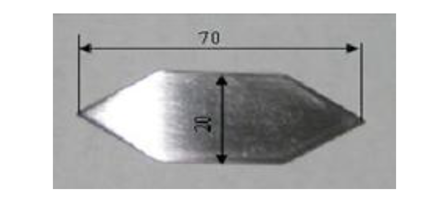
2.1. Material and Template

PMMA substrate samples with a thickness of 3 mm and side lengths of 90 and 70 mm were cut from a PMMA block with a low-speed diamond saw. A specially designed stainless steel template with side lengths of 70 and 20 mm and a thickness of 0.86 mm used for hot embossing is shown in Figure 1. The template was then sanded and polished to minimize surface roughness and was hot embossed on the PMMA substrate specimens.
Figure 1. Stainless steel template insert of the gravitational field flow fractionation device.
Micromachines 05 00139 g001

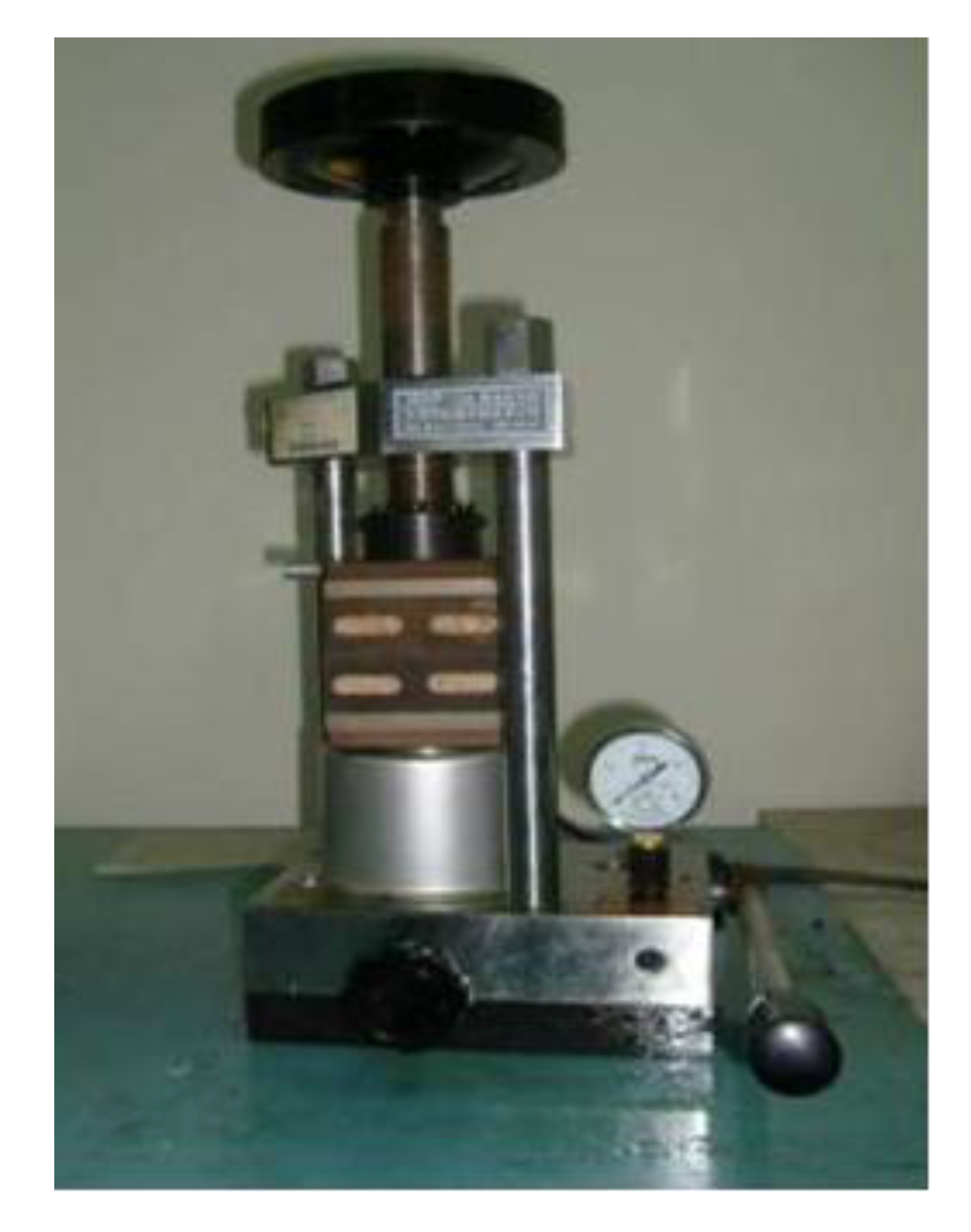
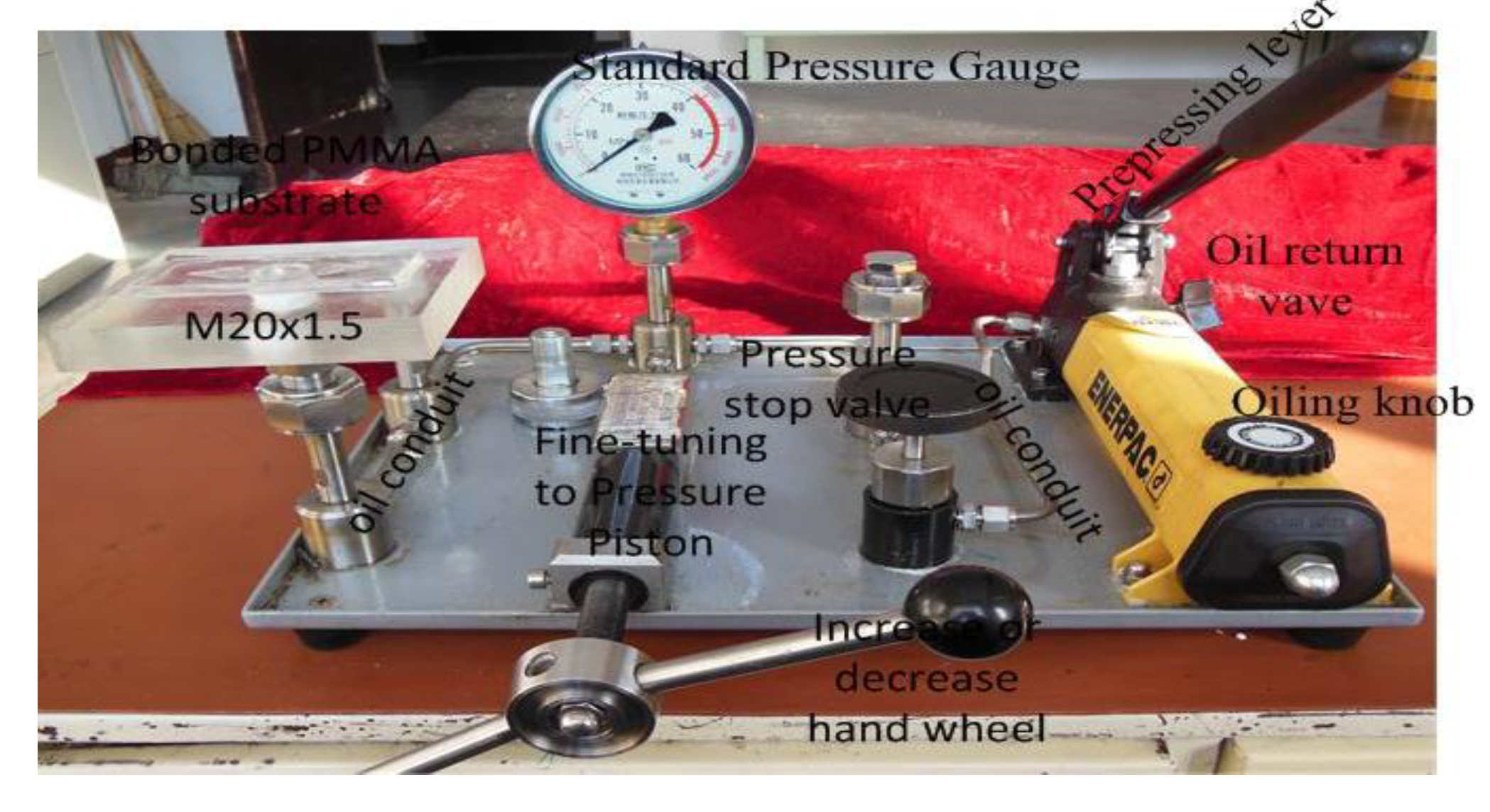
2.2. Experimental Setup

Figure 2 shows the schematic of the apparatus for the hot embossing. This apparatus consists of a manual lifting screw, a hydraulic cylinder, a pressure handle, a pressure gage and a dual channel temperature controller. This apparatus has a maximum load capacity of 48.6 kN with a resolution of 810 N. The manual lifting screw controls the displacement of the top heating block. The dual temperature controller allows independent heating control of the top and bottom heating block, which can achieve a maximum temperature of 250 °C. Natural cooling in air was used for the present study. The installation of insulation was also done in the system for the purpose of improving the quality of the embossing parts. The hot embossing apparatus will be used in the thermal bonding process.
Figure 2. Hot embossing and thermal bonding machine.
Micromachines 05 00139 g002

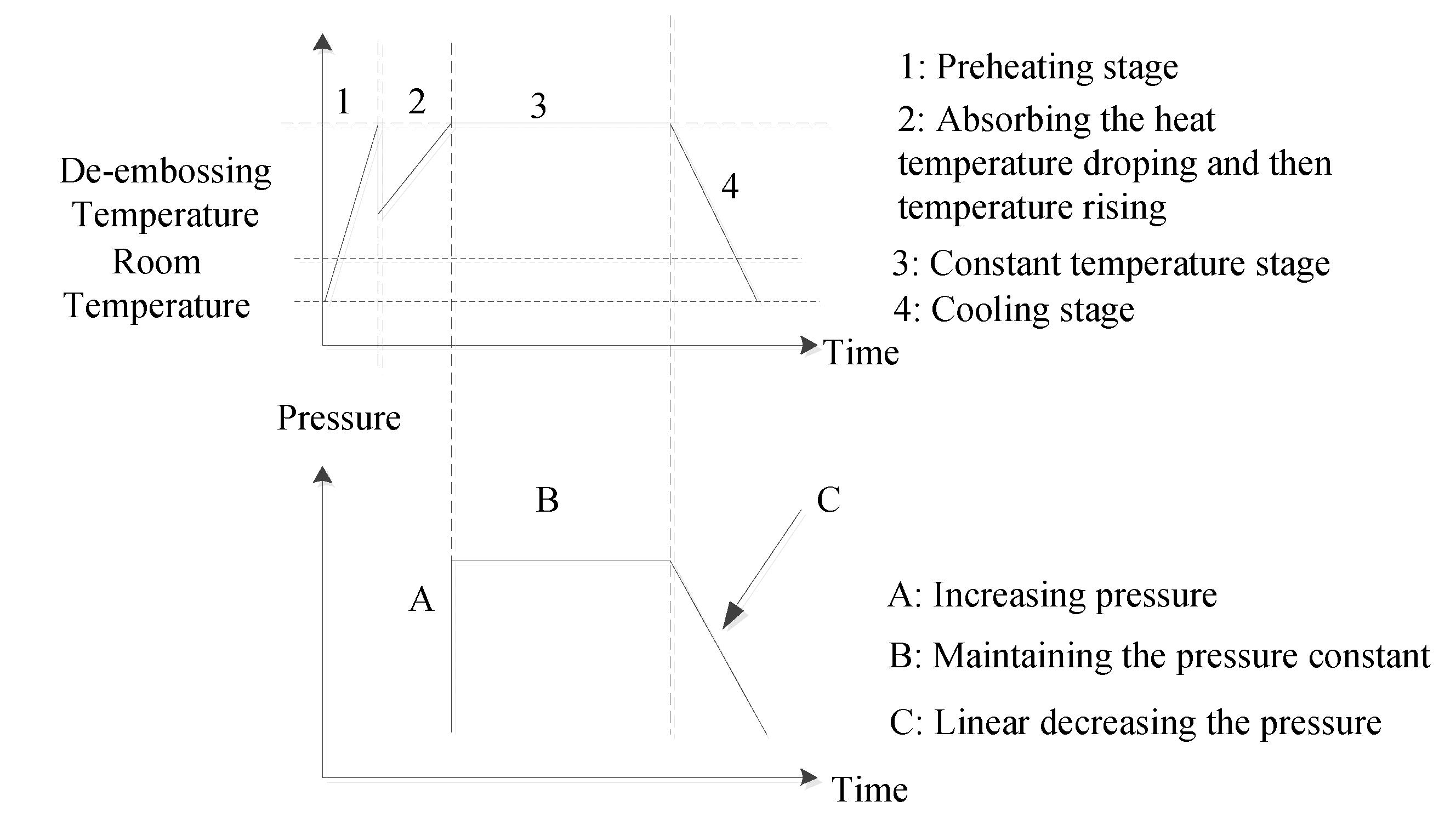
2.3. Hot Embossing Process

Isothermal hot embossing was used in the present study. The product qualities are affected by the main process parameters, such as the embossing temperature, the embossing pressure, the embossing time and the unloading pressure. Various temperature-pressure profiles result in different embossing cycles.
In this study, a temperature decrease stage was found, due to the absence of a vacuum, which is different from the traditional isothermal hot embossing process; so, the substrate could be pressed under the embossing temperature and the linear unloading pressure.
The temperature-pressure profiles for the hot embossing cycles are shown in Figure 3. For the temperature the Profiles 1, 2, 3 and 4, they were referred to as the preheating stage, the substrate heating stage, the constant temperature stage and the cooling stage, respectively. For the pressure Profiles A, B and C, they were referred to as the direct pressure stage, the keeping pressure stage and the decreasing pressure stage, respectively. The experiment details are described as follows.
(1) The top and bottom heating blocks were preheated to the scheduled embossing temperatures. The heating rate is 1 °C/s. Then, the template and substrate were inserted between the top and bottom blocks and continued heating. Meanwhile, as the template and substrate absorbed the heat, the temperature of the hot press dropped.
(2) Once the temperature reached the embossing temperature, the heating rate was adjusted to 0.3~0.5 °C/s. At the same time, the substrate was directly pressurized to the embossing pressure; the embossing temperature and pressure were maintained for about 3~5 min.
(3) After the embossing stage, the method natural cooling in air was adopted to remove residual stress, due to the embossing pressure of PMMA without a vacuum. The top and bottom surface temperature of the heating block should be kept consistent in the cooling process; otherwise, residual stress would make the substrate deform in the de-molding process.
Figure 3. The pressure-temperature profile for hot embossing.
Micromachines 05 00139 g003

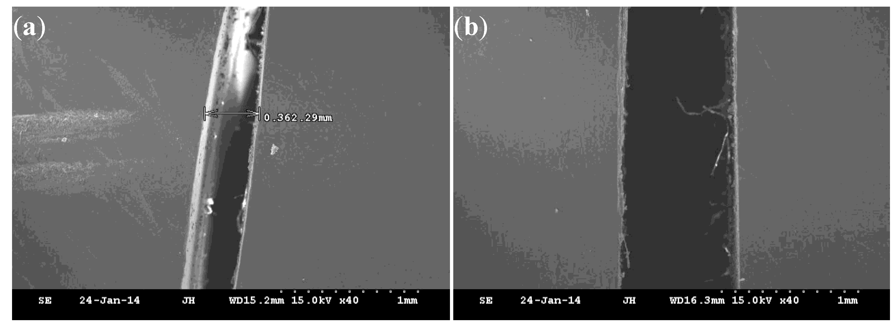
2.4. The Channel Dimension Measurement

The channel dimension of the PMMA substrate was measured by a laser CCD (LK-G150, Keyence, Elmwood Park, NJ, USA). The measured positions are the top, middle and bottom parts of the channel, and each position was measured three times to obtain the average value. Evaluation indexes were used to analyze the influence of the hot embossing parameters on the channel dimension. The evaluation indexes are equal to the ratio of the channel dimension, such as the length, width and depth, to the original substrate thickness.

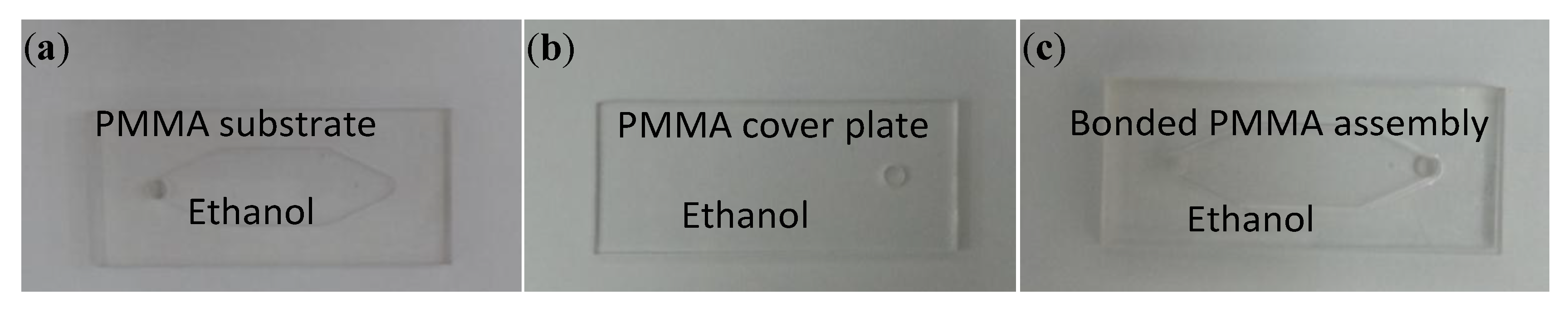
2.5. Hot Bonding Process

Figure 4 shows the overall scheme for bonding two PMMA substrates via ethanol treatment and then hot pressing. Prior to bonding, through-holes with a diameter of 5 mm were drilled on the PMMA substrate at a position corresponding to the inlet of the field flow fractionation devices and the PMMA cover plate at positions corresponding to the outlet of field flow fractionation devices. These PMMA substrates and cover plates were then ultrasonically cleaned in ethanol at 50 °C for 20 min, followed by drying in a vacuum furnace at 80 °C for 6 h with a vacuum pressure of 0.1 MPa. The dried PMMA substrate and the cover plate were then brushed with ethanol (95%) on their surfaces, aligned according to the positions of their inlet and outlet, mechanically clamped and thermally bonded at 45 °C for 90 s at a bonding pressure of 1.5 kPa.
Figure 4. Overall procedure for the bonding of two polymethylmethacrylate (PMMA) substrates (70 mm × 20 mm) via ethanol treatment and then hot pressing. (a) The PMMA substrate in the ethanol treatment; (b) the PMMA cover plate in the ethanol treatment; (c) the bonded PMMA assembly.
Micromachines 05 00139 g004

2.6. Bonding Performance Analysis

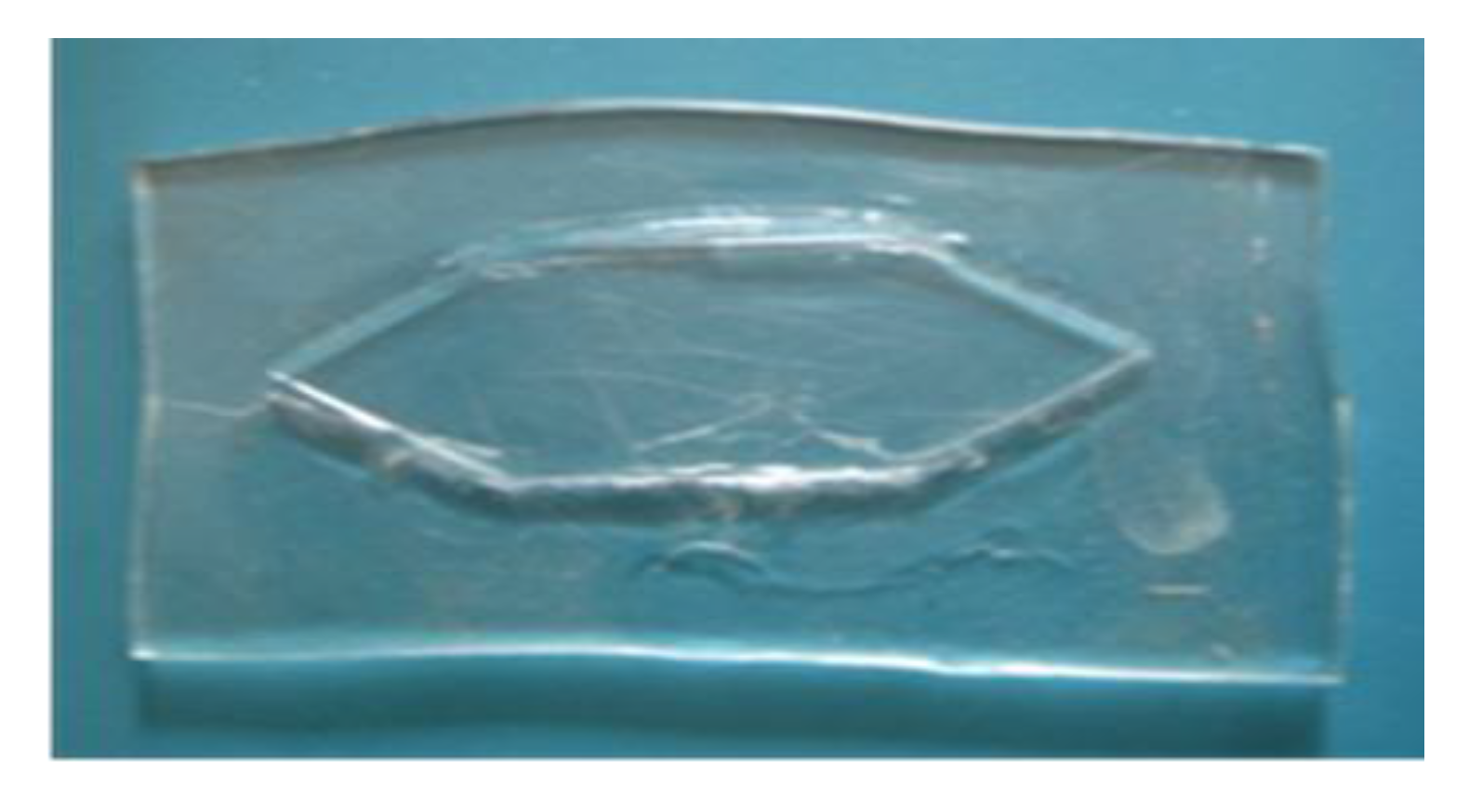
2.6.1. Separation Channel Characterization Test

The separation channel test was performed on a fractionation device with a channel size of 70 mm × 20 mm × 0.5 mm fabricated with minimum bonding pressure and temperature by injecting black ink that was washed away by a carrier liquid. The flow rate was 99.99 mL/h. A rubber tube of ID = 5 mm was used to connect the device inlet and a mechanical pump (Microinfusion Pump WZ-50C2, Zhejiang University). The hold time for the common carrier liquid is 20 min, and the time for washing the injected black ink is 40 min to observe the flow characteristic of the carrier liquid and the leak-proof ability.

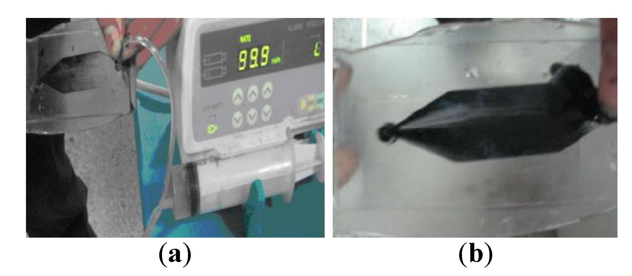
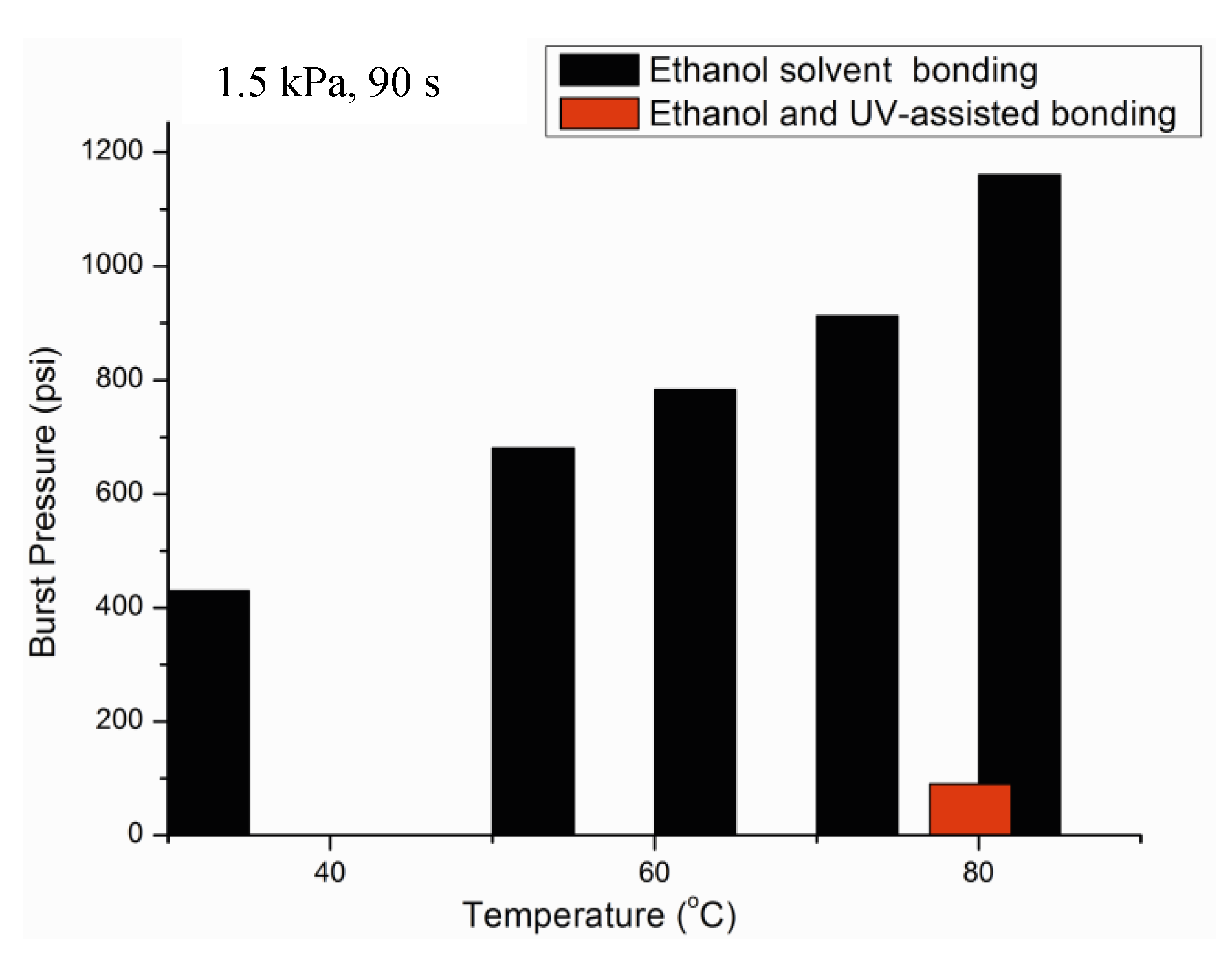
2.6.2. Burst Pressure Test

The burst pressure test for the ethanol solvent bonding was measured using an oil hydraulic system, as shown in Figure 5. A connection was made to a hydraulic source (Model KY2012, Beijing Kai Hang Ke Ji Co., Ltd., Beijing, China), which was fitted with a pressure transducer with an accuracy of 1.6% full span F.S. in the range of 0–60 MPa. The sample was pressed through a pre-pressure lever and a turn-off pressure stop valve. Subsequently at a faster rate, the pressure was increased by using a hand wheel until it reached a maximum value, before it dropped suddenly. The maximum value is the burst pressure.

2.7. Separation Experiment

2.7.1. Operating Principle and Basic Structure

Gravitational field flow fractionation is characterized by gravitational force as the external field applied perpendicularly to the direction of the sample, while the hydrodynamic lift is applied in a backward manner, due to the aspect ratio of the gravitational channel with the laminar parabolic profile that develops. These two counteracting forces modulate the location of different particles with respect to the accumulation wall. Based on this, particles of different sizes are separated.
The gravitational field flow fractionation device is composed of a cover plate and a substrate with separation channel-like ribbon by using hot embossing and the solvent bonding method. The total dimension is 500 mm-long and 60 mm in width, and the separation channel is 0.5 mm in depth, 40 mm in width and 463 mm in length. Its inlet channel has an inclined angle of 54°.
Figure 5. The burst test setup connected with the bonded PMMA substrate.
Micromachines 05 00139 g005

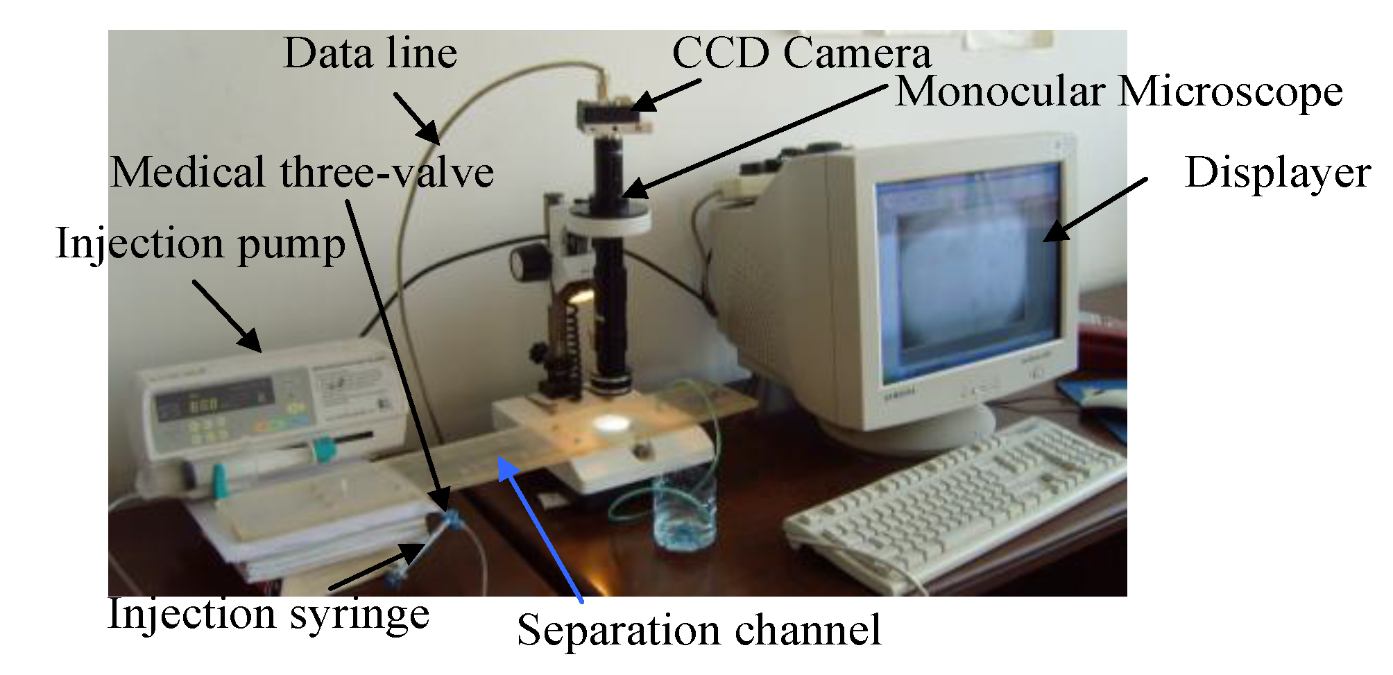
2.7.2. Experiment Setup

PMMA gravitational field flow fractionation was chosen to evaluate the separation performance. The separation experiment setup is shown in Figure 6. In the evaluation of the separation properties, a monocular microscope, DTX-1 (Taike Instrument Inc., Beijing, China), was used to observe the fractionation process, and a CCD camera (Basler 102f, Basler, Ahrensburg, German) was used to capture the image at the outlet channel.
Figure 6. Experimental setup of the gravitational field flow fractionation system.
Micromachines 05 00139 g006

3. Results and Discussion

3.1. Influence of Hot Embossing Parameters

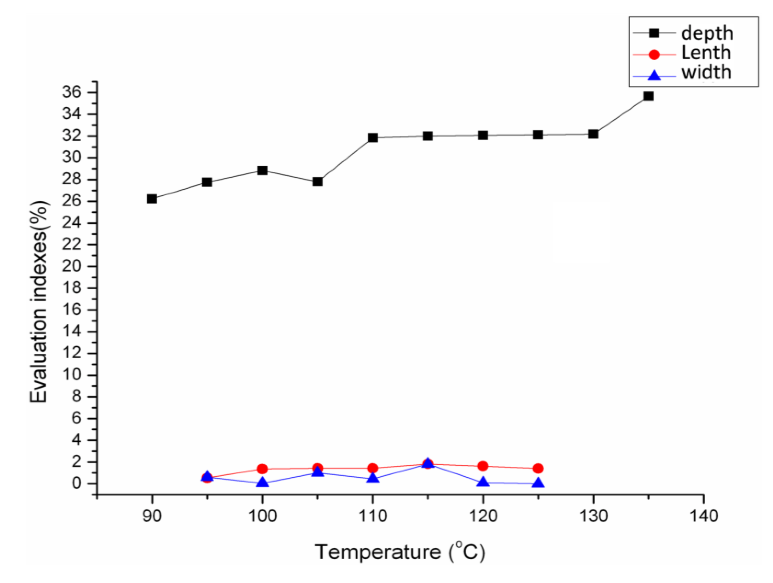
3.1.1. Effect of Hot Embossing Temperature

Figure 7 shows the effect of embossing temperature on the channel dimensions. It can be seen from the figure that the temperature has no significant effect on both the channel length and width. However, temperature has some effect on the channel depth. The channel was deeper at a higher temperature range (110–135 °C) than that at a lower temperature range (90–105 °C). The possible reason is that when the embossing temperature is higher than the glass transition temperature (105 °C), PMMA becomes soft, which causes a deeper embossing channel. This indicates that under higher hot embossing temperatures, a desirable embossing depth can be obtained.
Figure 7. The relationship between temperature and evaluation indexes.
Micromachines 05 00139 g007
When the embossing temperature is higher than 135 °C, a bulging phenomenon happens; the embossing depth is 0.88 mm, larger than the original thickness of the substrate, producing melting along the edges, blisters, pitting, wrinkling and yellow dots on the product surface, as shown in Figure 8. This means that a temperature higher than 135 °C is not suitable for hot embossing.
Figure 8. An unsuccessful sample showing the partial melting phenomenon along the edge, blisters, pitting, wrinkling and yellow dots on the product surface.
Micromachines 05 00139 g008

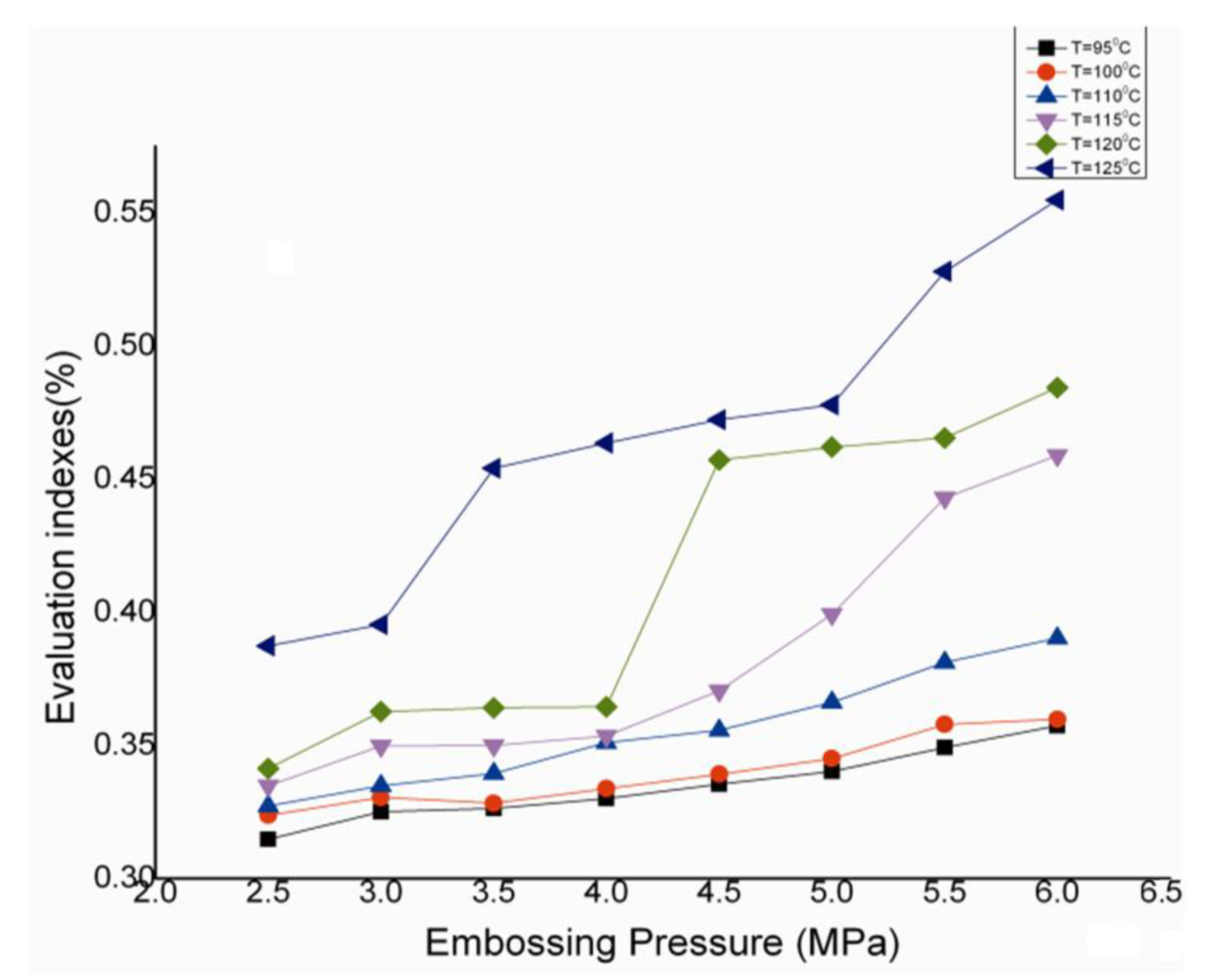
3.1.2. Effect of Hot Embossing Pressure

Figure 9 shows the relationship between embossing pressures and evaluation indexes (depth/thickness) under different embossing temperatures. It was found that the evaluation index increases more rapidly with the increase of the embossing pressure under a higher embossing temperature than that under a lower embossing temperature. This means that under a higher embossing temperature, a deeper channel can be achieved with a higher embossing pressure applied. Furthermore, the device embossed under the glass transition temperature range exhibits higher replication accuracy.
Figure 9. The relationship between embossing pressure and evaluation indexes (depth/thickness) under different temperatures.
Micromachines 05 00139 g009

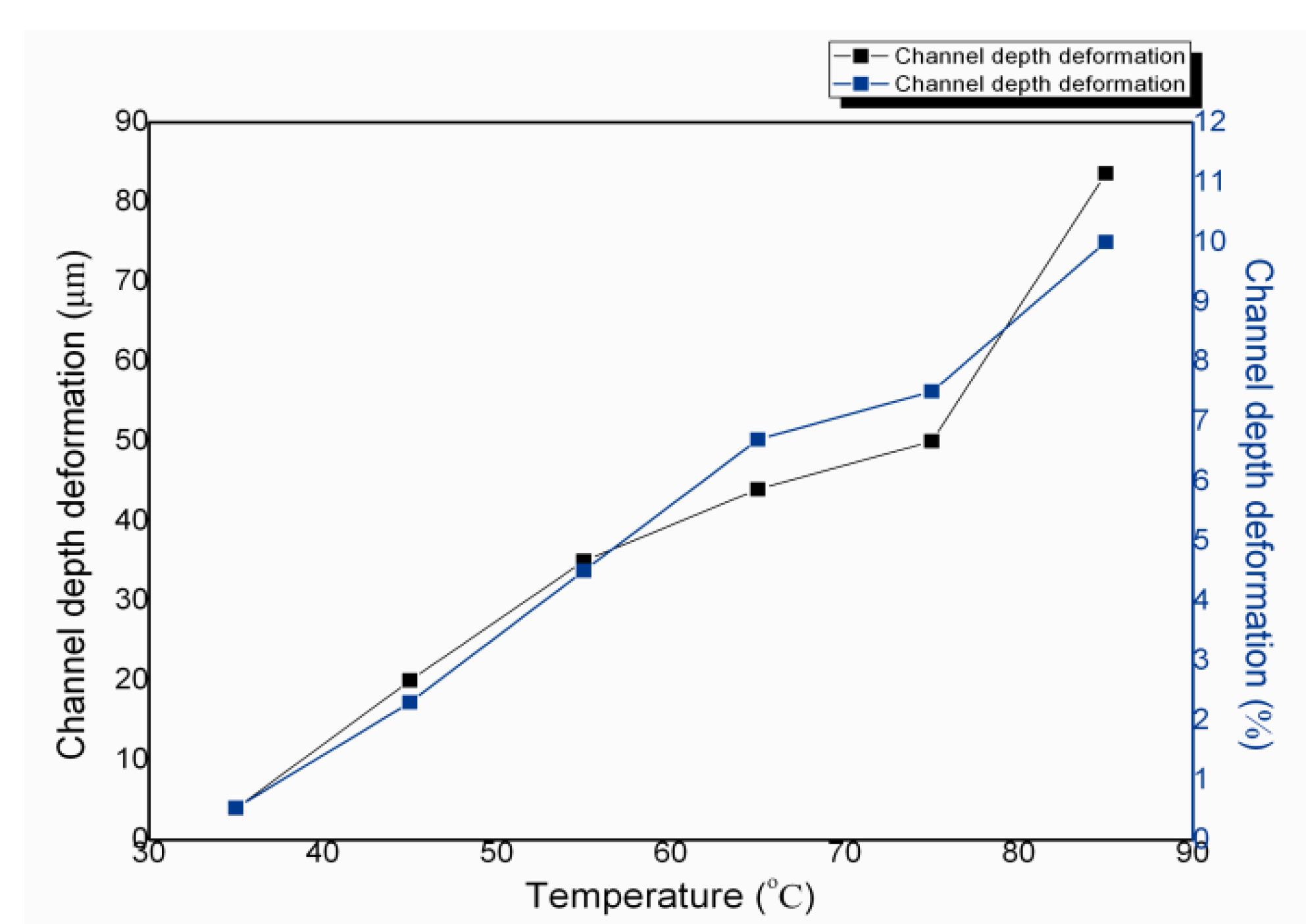
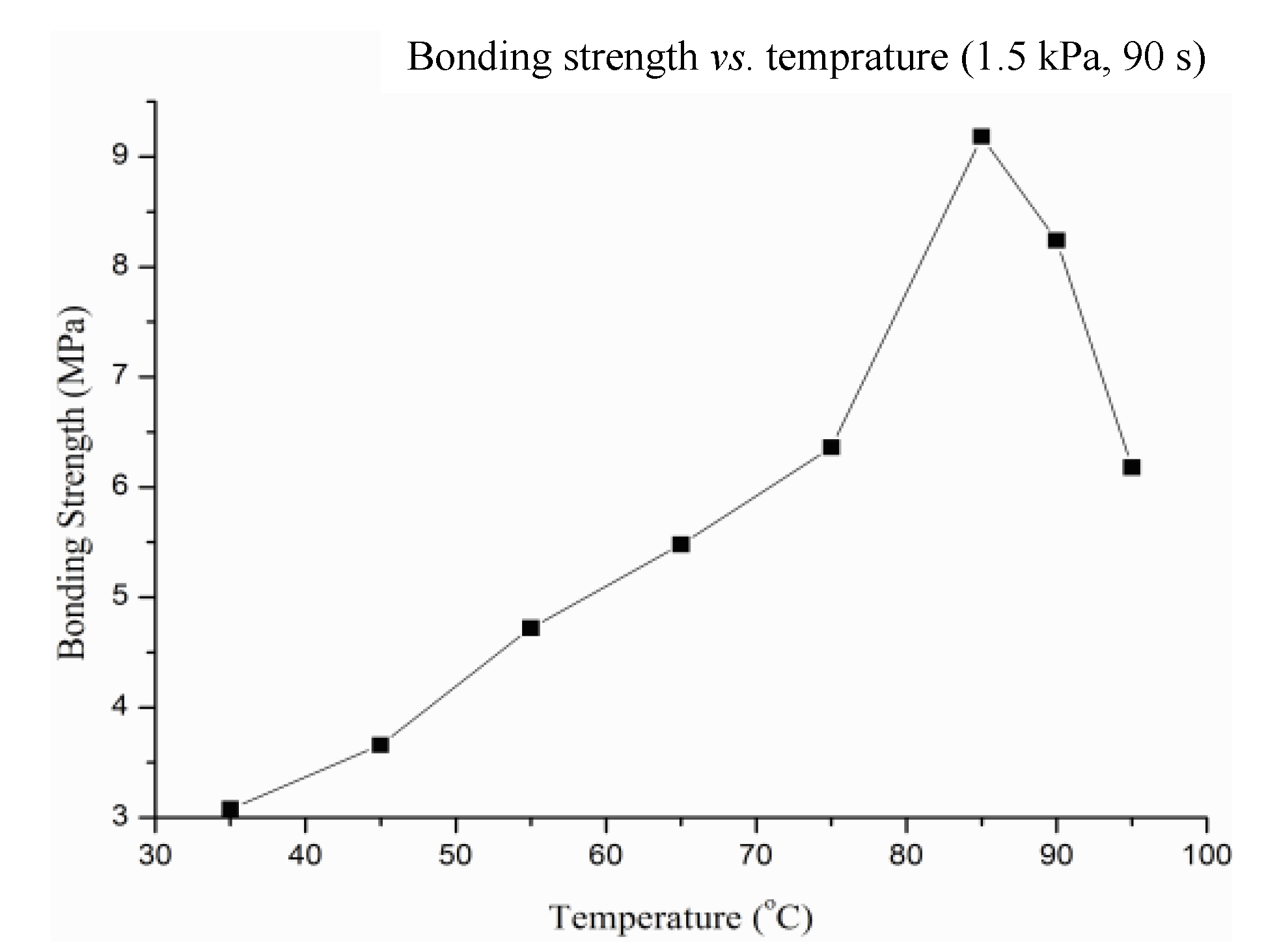
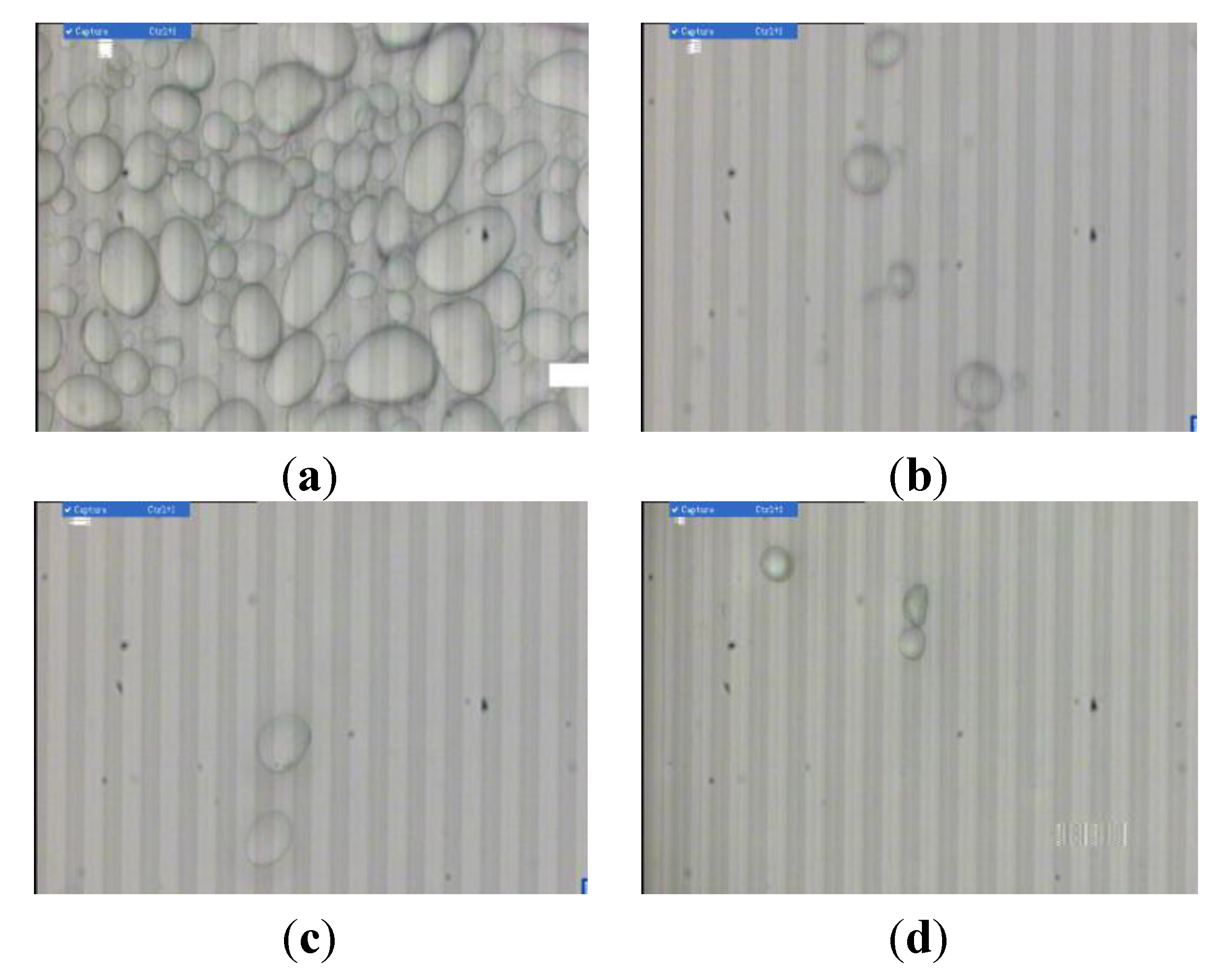
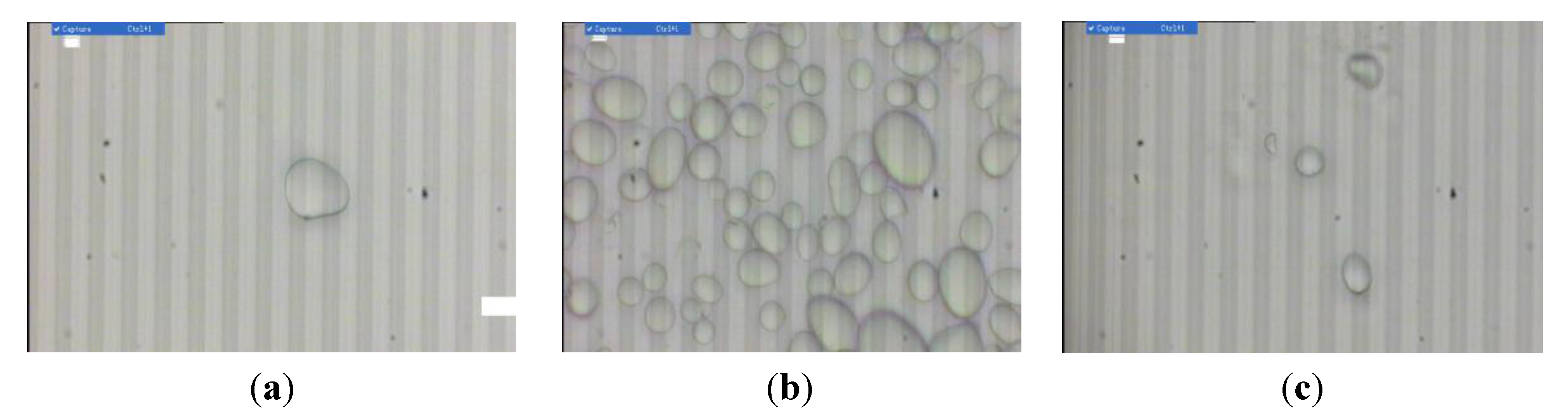
3.2. Influence of Thermal Bonding Parameters

Figure 10a shows the channel under a high thermal bonding temperature of ~95 °C. It can be seen that the channel depth is 362.29 μm, which is much smaller than before the hot bonding process (862.68 μm). This indicates that a high hot bonding temperature results in a serious deformation of the channel. As shown in Figure 10b, while the bonding temperature was held at 85 °C, no cleft and clogging were not found between the upper and lower substrates, and the channel remained almost the same as the embossing channel. Therefore, the bonding temperature was held below 85 °C.
Figure 11a is a cross-section image of the channel before bonding. The depth averaged 862.68 ± 1.00 μm. Figure 11b shows the cross-section image of the channel at a 35 °C bonding temperature. The depth averaged 858.00 ± 1.00 μm. Therefore, the absolute decrease of the channel depth is 4.68 μm, and the sample’s deformation is calculated to be 0.54%.
Figure 10. Cross-section pictures of the channel at bonding temperatures of 95 °C (a) and 85 °C (b).
Micromachines 05 00139 g010
Figure 11. Cross-section images of the channel before bonding (a) and the channel at a bonding temperature of 35 °C (b).
Micromachines 05 00139 g011
To further investigate the influence of bonding temperature on the deformation, we changed the bonding temperatures from 35 to 85 °C, while keeping the bonding pressure of 1.5 kPa and the bonding time of 90 s. When the bonding temperature was held at 35 °C, the deformation value of the channel depth is 4.68 μm (minimum value); the percentage of the corresponding deformation value is 0.54%. The bonding deformation increased with the increase in temperature. When the temperature was held at 85 °C, the deformation value of the channel depth is up to 85 μm (maximum value) with a standard deviation of 1.0 μm; the percentage of the corresponding deformation value is 9.7%, as shown in Figure 12.
Figure 12. The relationship between bonding temperature and channel depth deformation.
Micromachines 05 00139 g012
The relationship between bonding temperature and bonding strength was measured through a universal testing machine. The bonding temperature range of the sample is 35~95 °C, and the pressure is 1.5 kPa, with a bonding time of 1–2 min. The lapped surface has an area varying between 1 mm2 and 1.5 mm2. All the samples were torn apart at the base material, indicating that permanent bonding was obtained. Figure 13 shows the bonding temperature’s effect on bonding strength. In this figure, it can be seen that the ethanol solvent bonding has a very good bonding strength and the lowest possible bonding temperature, 35 °C. The bonding strength for PMMA substrates at 35 °C was 3.02 MPa, which is much stronger than that (0.64 MPa) for tradition thermal bonding at 100 °C [27]. The bonding strength increases with increasing bonding temperature from 35 °C to 85 °C. When the bonding temperature was 85 °C, which is lower than the glass transition temperature, the bonding strength was up to 8.1 MPa. When the temperature was above 85 °C, the bonding strength decreased as the temperature increased. This is not surprising, because at a high temperature, PMMA tends to deform under pressure, resulting in a relatively low pulling force, due to the stress concentration on the fractured surface while pulling the overlapped PMMA substrate.
Figure 13. The relationship between bonding temperature and bonding strength.
Micromachines 05 00139 g013
Previous studies on the bonding of microfluidic chips revealed that factors, such as the adoption of the solvent and the depth/width (aspect ratio) of chip structure, have a significant influence on the deformation of microchannel [32]. The deformation percentage of the microchannel in the PMMA thermally bonded microfluidic chip in the absence of solvent is 11.9% at a minimum, and its bonding strength is 2.10 MPa at a maximum [33]. The deformation percentage of the microchannel in the microfluidic chip (aspect ratio: 0.4) with isopropanol solvent is 2%–6%, and its bonding strength is 0.3 MPa [34]. The deformation percentages of the microchannel in the microfluidic chip (aspect ratio: 0.34 and 0.03) with ethylene glycol dimethacrylate is 1.6 ± 0.3% and 30%, respectively [32]. The bonding strengths with ethanol solvent (aspect ratio: 0.043) are 3.05–8.1 MPa, which are much stronger than those with other solvents or without the solvent bonding reported above. The deformation percentage is 0.54% with ethanol solvent (aspect ratio: 0.043), which is much lower than that with ethylene glycol dimethacrylate (aspect ratio: 0.03).

3.3. Gravitational Field Flow Fractionation Characteristic Test and Burst Pressure Test

The gravitational field flow fractionation characteristic was tested with black ink. The flow rate was 0.99 mL/h, and the ink retention time was approximately 40 min inside the channel. It was found from Figure 14a that the ink solution passed through the channel without leakage or destruction. Meanwhile, the carrier liquid flew through the channel as time went by, forming a liquid line along the centerline of the channel, which probably showed the maximum flow rate of the centerline of the channel. This phenomenon is accordant with the parabolic laminar hypothesis of field flow fractionation, as shown in Figure 14b.
The burst pressure test was also performed by an oil hydraulic system. As shown in Figure 15, the burst pressure strength increased significantly with increasing bonding temperature. The channel that was bonded at 35 °C exhibited a high burst pressure of 430 psi. The burst pressures of the PMMA gravitational field flow fractionation device at the thermal bonding temperatures of 65, 75 and 85 °C with ethanol solvent are very high (~783, ~913 and above 1,160 psi, respectively), which are much higher than that obtained at 77 °C [35]. Generally, the inner pressure of the traditional gravitational field flow fractionation device cannot be higher than 435 psi. However, the PMMA gravitational field flow fractionation device with ethanol solvent thermal bonding exhibits a very high burst pressure. Therefore, it will have a wide range of applications.
Figure 14. (a) The injection of black ink into the channel; (b) the result of the parabolic laminar hypothesis.
Micromachines 05 00139 g014
Figure 15. The effect of bonding temperature on burst pressure strength for ethanol bonded substrates [35].
Micromachines 05 00139 g015

3.4. Fractionation Test Results

Figure 16a shows the non-separated wheat particles of three different sizes. The injection rate of the fractionation flow was 1 mL/min with 0.2 mL per injection and a 2-min relaxation time. After field-flow fractionation, the wheat particle agglomerates are separated into three groups in sequence at times of 6 min 30 s, 6 min 40 s and 7 min 5 s, with roughly the same particle size of the powders in each group, as shown in Figure 16b–d. The time taken for fractionation in the present study is 1 min longer than the traditional gravitational field-flow fractionation method. This is due to the fact that for the traditional gravitational field-flow fractionation method, glass plates with ultra-low surface roughness were used, whereas the PMMA fractionation devices used in the present study have a much higher surface roughness (Ra = 0.21 μm) after embossing treatment. In order to testify to the fractionation selectivity effect of the fabricated PMMA fractionation devices, separation experiments for starch were performed. Form Figure 17, it can be seen that particle agglomerates with different sizes are effectively separated.
Figure 16. The separation results of the wheat particles. (a) Non-separated wheat particles; (b) the first separation sample; (c) the second separation sample; (d) the third separation sample.
Micromachines 05 00139 g016
Figure 17. The separation results of starch particles. (a) Non-separated starch particles; (b) the first separation sample; (c) the second separation sample.
Micromachines 05 00139 g017

4. Conclusions

In conclusion, a novel method for fabricating gravitational field flow fractionation devices was developed by using hot embossing and the ethanol solvent bonding method. In the hot embossing process, the major influencing factors are hot embossing temperature and hot embossing pressure. In the thermal bonding process, a very effective ethanol solvent bonding method was adopted. In this way, the thermal bonding process can be done under low temperature. Even at 35 °C, the bonding strength of PMMA substrates can reach 3.05 MPa, and the deformation percentage of the channel is 0.54%, which are satisfactory parameters for real applications. The burst pressure of the as-prepared PMMA gravitational field flow fractionation device can reach up to ~1160 psi at a bonding temperature of 85 °C. Surprisingly, the fabrication of the PMMA gravitational field flow fractionation device can be finished in less than 5 min. The hot embossing/thermal bonding method developed is economically efficient, due to the reusability of the stainless steel template and the hot press without a vacuum. The successful separation of wheat and starch particles of different sizes by the as-prepared PMMA gravitational field flow fractionation device indicates that it will have potential applications in the separation and purification of materials. In addition, PMMA gravitational field flow fractionation can be applied to mass production, and this fabrication methodology may also be suitable for other polymeric fabrications.

Author Contributions

Kaijun Yang is the person who makes substantial contributions to conception and design, and experimental experiment, and gives final approval of the version to be submitted.

Conflicts of Interest

The author declares no conflict of interest.

References

  1. Urbánková, E.; Vacek, A.; Nováková, N.; Matulík, F.; Chmelík, J. Investigation of red blood cell fractionation by gravitational field-flow fractionation. J. Chromatogr. B Biomed. Sci. Appl. 1992, 583, 27–34. [Google Scholar] [CrossRef]
  2. Lattuada, D.; Roda, B.; Pignatari, C.; Magni, R.; Colombo, F.; Cattaneo, A.; Zattoni, A.; Cetin, I.; Reschiglian, P.; Bolis, G. A tag-less method for direct isolation of human umbilical vein endothelial cells by gravitational field-flow fractionation. Anal. Bioanal. Chem. 2013, 405, 977–984. [Google Scholar] [CrossRef]
  3. Ibrahim, T.; Battu, S.; Cook-Moreau, J.; Cardot, P. Instrumentation of hollow fiber flow field flow fractionation for selective cell elution. J. Chromatogr. B 2012, 901, 59–66. [Google Scholar] [CrossRef]
  4. Roda, B.; Reschiglian, P.; Alviano, F.; Lanzoni, G.; Bagnara, G.P.; Ricci, F.; Buzzi, M.; Tazzari, P.L.; Pagliaro, P.; Michelini, E.; et al. Gravitational field-flow fractionation of human hemopoietic stem cells. J. Chromatogr. A 2009, 1216, 9081–9087. [Google Scholar]
  5. Benincasa, M.-A.; Moore, L.R.; Williams, P.S.; Poptic, E.; Carpino, F.; Zborowski, M. Cell sorting by one gravity SPLITT fractionation. Anal. Chem. 2005, 77, 5294–5301. [Google Scholar] [CrossRef]
  6. Mazanec, K.; Dycka, F.; Bobalova, J. Monitoring of barley starch amylolysis by gravitational field flow fractionation and MALDI-TOF MS. J. Sci. Food Agric. 2011, 91, 2756–2761. [Google Scholar] [CrossRef]
  7. Chmelík, J.; Mazanec, K.; Bohačenko, I.; Psota, V. Relationship between the ratio of large and small starch granules determined by gravitational field-flow fractionation and malting quality of barley varieties. J. Liquid Chromatogr. Relat. Technol. 2007, 30, 1289–1301. [Google Scholar] [CrossRef]
  8. Chmelík, J.; Krumlová, A.; Budinská, M.; Kruml, T.; Psota, V.; Bohac̆enko, I.; Mazal, P.; Vydrová, H. Comparison of size characterization of barley starch granules determined by electron and optical microscopy, low angle laser light scattering and gravitational field-flow fractionation. J. Inst. Brew. 2001, 107, 11–17. [Google Scholar] [CrossRef]
  9. Psota, V.; Bohačenko, I.; Hartmann, J.; Budinská, M.; Chmelík, J. Comparison of the GFFF and LALLS methods for the measurement of starch granule size distribution in spring barley caryopses. J. Inst. Brew. 2002, 108, 200–203. [Google Scholar] [CrossRef]
  10. Janoušková, J.; Budinská, M.; Plocková, J.; Chmelı́k, J. Optimization of experimental conditions for the separation of small and large starch granules by gravitational field-flow fractionation. J. Chromatogr. A 2001, 914, 183–187. [Google Scholar] [CrossRef]
  11. Contado, C.; Reschiglian, P.; Faccini, S.; Zattoni, A.; Dondi, F. Continuous split-flow thin cell and gravitational field-flow fractionation of wheat starch particles. J. Chromatogr. A 2000, 871, 449–460. [Google Scholar] [CrossRef]
  12. Contado, C.; Hoyos, M. SPLITT Cell Analytical Separation of Silica Particles. Non-Specific Crossover effects: does the shear-induced diffusion play a role? Chroma 2007, 65, 453–462. [Google Scholar] [CrossRef]
  13. Reschiglian, P.; Melucci, D.; Torsi, G.; Zattoni, A. Standardless method for quantitative particle-size distribution studies by gravitational field-flow fractionation.Application to silica particles. Chroma 2000, 51, 87–94. [Google Scholar] [CrossRef]
  14. Pazourek, J.; Chmelík, J. Characterization of chromatographic silica gel support particles by gravitational field-flow fractionation. J. Microcolumn Sep. 1997, 9, 611–617. [Google Scholar] [CrossRef]
  15. Park, M.R.; Chum, Y.S.; Kang, D.Y.; Yu, S.K.; Choi, S.H.; Lee, K.H.; Lee, S. Effect of reaction parameters on size distribution of emulsion-polymerized polystyrene latex beads studied by gravitational flow-flow fractionation (GrFFF). J. Liquid Chromatogr. Relat. Technol. 2009, 32, 909–922. [Google Scholar] [CrossRef]
  16. Meng, H.; Caldwell, K.D.; Calvin Giddings, J. Examination of residues from coal liquefaction by steric field-flow fractionation. Fuel Process. Technol. 1984, 8, 313–320. [Google Scholar] [CrossRef]
  17. Roda, B.; Reschiglian, P.; Zattoni, A.; Tazzari, P.; Buzzi, M.; Ricci, F.; Bontadini, A. Human lymphocyte sorting by gravitational field-flow fractionation. Anal. Bioanal. Chem. 2008, 392, 137–145. [Google Scholar] [CrossRef]
  18. Roda, B.; Casolari, S.; Reschiglian, P.; Mirasoli, M.; Simoni, P.; Roda, A. Hybrid gravitational field-flow fractionation using immunofunctionalized walls for integrated bioanalytical devices. Anal. Bioanal. Chem. 2009, 394, 953–961. [Google Scholar] [CrossRef]
  19. Magliulo, M.; Roda, B.; Zattoni, A.; Michelini, E.; Luciani, M.; Lelli, R.; Reschiglian, P.; Roda, A. An innovative, flow-assisted, noncompetitive chemiluminescent immunoassay for the detection of pathogenic bacteria. Clin. Chem. 2006, 52, 2151–2155. [Google Scholar] [CrossRef]
  20. Park, M.R.; Kang, D.Y.; Chmelik, J.; Kang, N.; Kim, J.S.; Lee, S. Different elution modes and field programming in gravitational field-flow fractionation: Effect of channel angle. J. Chromatogr. A 2008, 1209, 206–211. [Google Scholar]
  21. Plocková, J.; Chmelík, J. Different elution modes and field programming in gravitational field-flow fractionation: Field programming using density and viscosity gradients. J. Chromatogr. A 2006, 1118, 253–260. [Google Scholar] [CrossRef]
  22. Casolari, S.; Roda, B.; Mirasoli, M.; Zangheri, M.; Patrono, D.; Reschiglian, P.; Roda, A. Gravitational field-flow fractionation integrated with chemiluminescence detection for a self-standing point-of-care compact device in bioanalysis. Analyst 2013, 138, 211–219. [Google Scholar] [CrossRef]
  23. Messaud, F.A.; Sanderson, R.D.; Runyon, J.R.; Otte, T.; Pasch, H.; Williams, S.K.R. An overview on field-flow fractionation techniques and their applications in the separation and characterization of polymers. Progr. Polym. Sci. 2009, 34, 351–368. [Google Scholar] [CrossRef]
  24. Langer, R.; Tirrell, D.A. Designing materials for biology and medicine. Nature 2004, 428, 487–492. [Google Scholar] [CrossRef]
  25. Lin, M.-C.; Yeh, J.-P.; Chen, S.-C.; Chien, R.-D.; Hsu, C.-L. Study on the replication accuracy of polymer hot embossed microchannels. Int. Commun. Heat Mass Transf. 2013, 42, 55–61. [Google Scholar] [CrossRef]
  26. Yi, S.; Yien Chian, K.; Nam-Trung, N. Low-pressure, high-temperature thermal bonding of polymeric microfluidic devices and their applications for electrophoretic separation. J. Micromech. Microeng 2006, 16, 1681. [Google Scholar] [CrossRef]
  27. Zhu, X.; Liu, G.; Guo, Y.; Tian, Y. Study of PMMA thermal bonding. Microsyst. Technol. 2007, 13, 403–407. [Google Scholar]
  28. Kricka, L.J.; Fortina, P.; Panaro, N.J.; Wilding, P.; Alonso-Amigo, G.; Becker, H. Fabrication of plastic microchips by hot embossing. Lab Chip 2002, 2, 1–4. [Google Scholar]
  29. Chen, Z.; Gao, Y.; Lin, J.; Su, R.; Xie, Y. Vacuum-assisted thermal bonding of plastic capillary electrophoresis microchip imprinted with stainless steel template. J. Chromatogr. A 2004, 1038, 239–245. [Google Scholar]
  30. Li, J.M.; Liu, C.; Qiao, H.C.; Zhu, L.Y.; Chen, G.; Dai, X.D. Hot embossing/bonding of a poly(ethylene terephthalate) (PET) microfluidic chip. J. Micromech. Microeng. 2008, 18, 015008. [Google Scholar] [CrossRef]
  31. Roy, S.; Yue, C.Y.; Venkatraman, S.S.; Ma, L.L. Low-temperature (below Tg) thermal bonding of COC microfluidic devices using UV photografted HEMA-modified substrates: High strength, stable hydrophilic, biocompatible surfaces. J. Mater. Chem. 2011, 21, 15031–15040. [Google Scholar] [CrossRef]
  32. Umbrecht, F.; Müller, D.; Gattiker, F.; Boutry, C.M.; Neuenschwander, J.; Sennhauser, U.; Hierold, C. Solvent assisted bonding of polymethylmethacrylate: Characterization using the response surface methodology. Sens. Actuators A Phys. 2009, 156, 121–128. [Google Scholar]
  33. Sood, V. An Experimental Study on Thermal Bonding Effects of PMMA Based Micro-devices Using Hot Embossing; ProQuest: Ann Arbor, MI, USA, 2008. [Google Scholar]
  34. Hsu, Y.-C.; Chen, T.-Y. Applying Taguchi methods for solvent-assisted PMMA bonding technique for static and dynamic μ-TAS devices. Biomed. Microdevices 2007, 9, 513–522. [Google Scholar] [CrossRef]
  35. Tran, H.H.; Wu, W.; Lee, N.Y. Ethanol and UV-assisted instantaneous bonding of PMMA assemblies and tuning in bonding reversibility. Sens. Actuators B Chem. 2013, 181, 955–962. [Google Scholar] [CrossRef]

