Fabrication of Polydimethylsiloxane Microlenses Utilizing Hydrogel Shrinkage and a Single Molding Step

Abstract
:
1. Introduction
2. Fabrication
2.1. Equipment and Materials
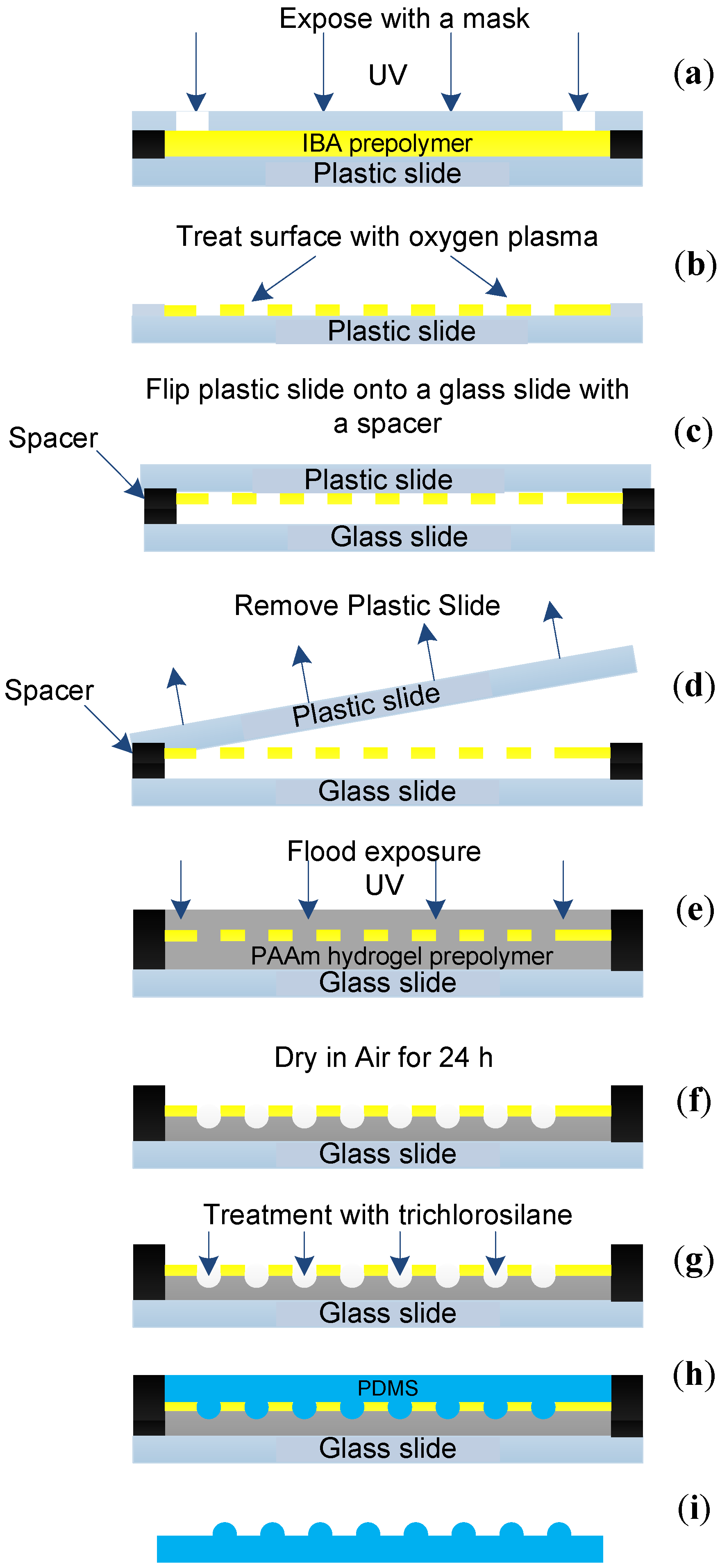
2.2. Microlens Array Fabrication


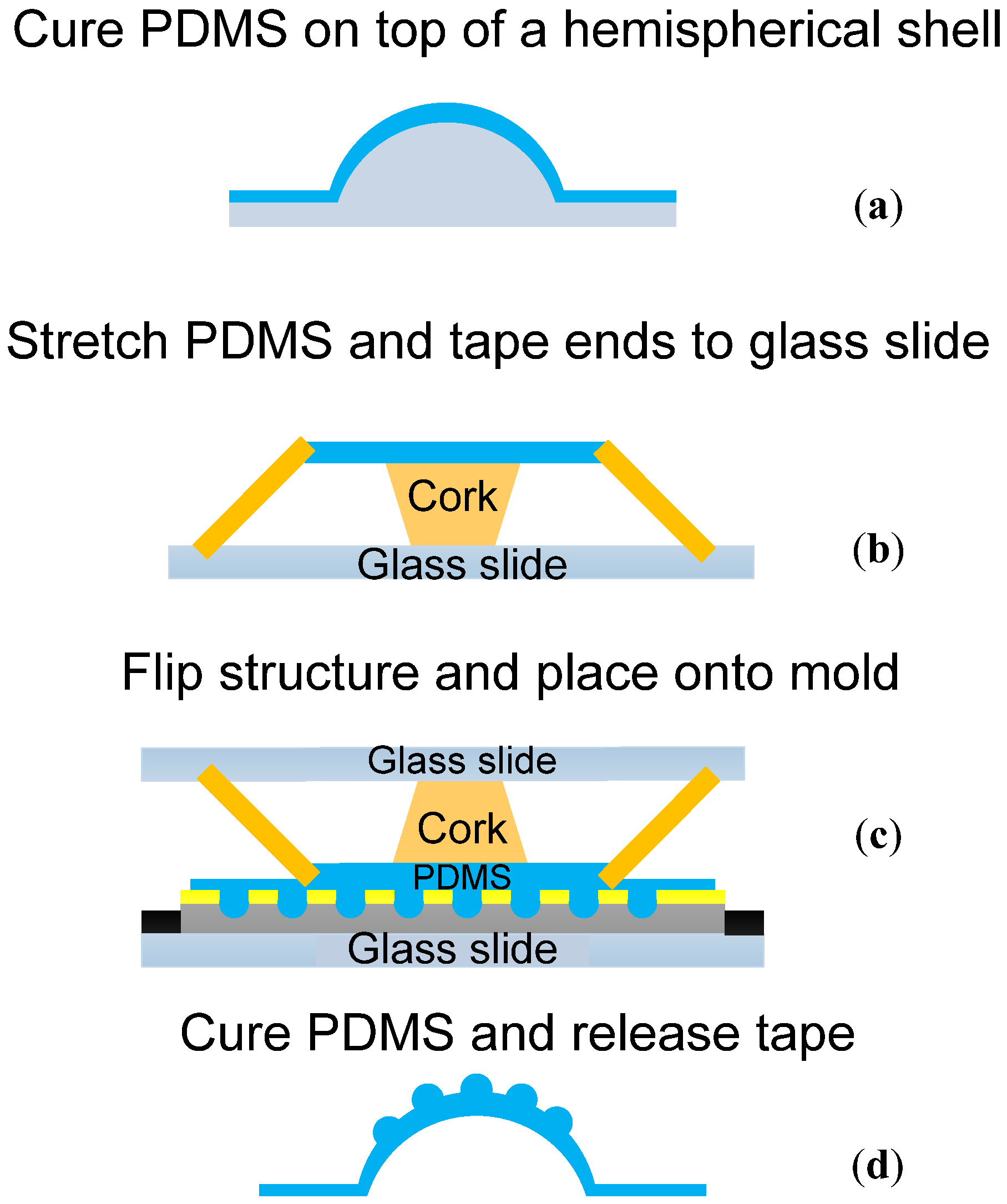
2.3. PDMS Compound Eye Fabrication
2.4. Solaris Compound Eye Fabrication

3. Results and Discussion
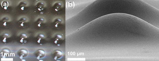
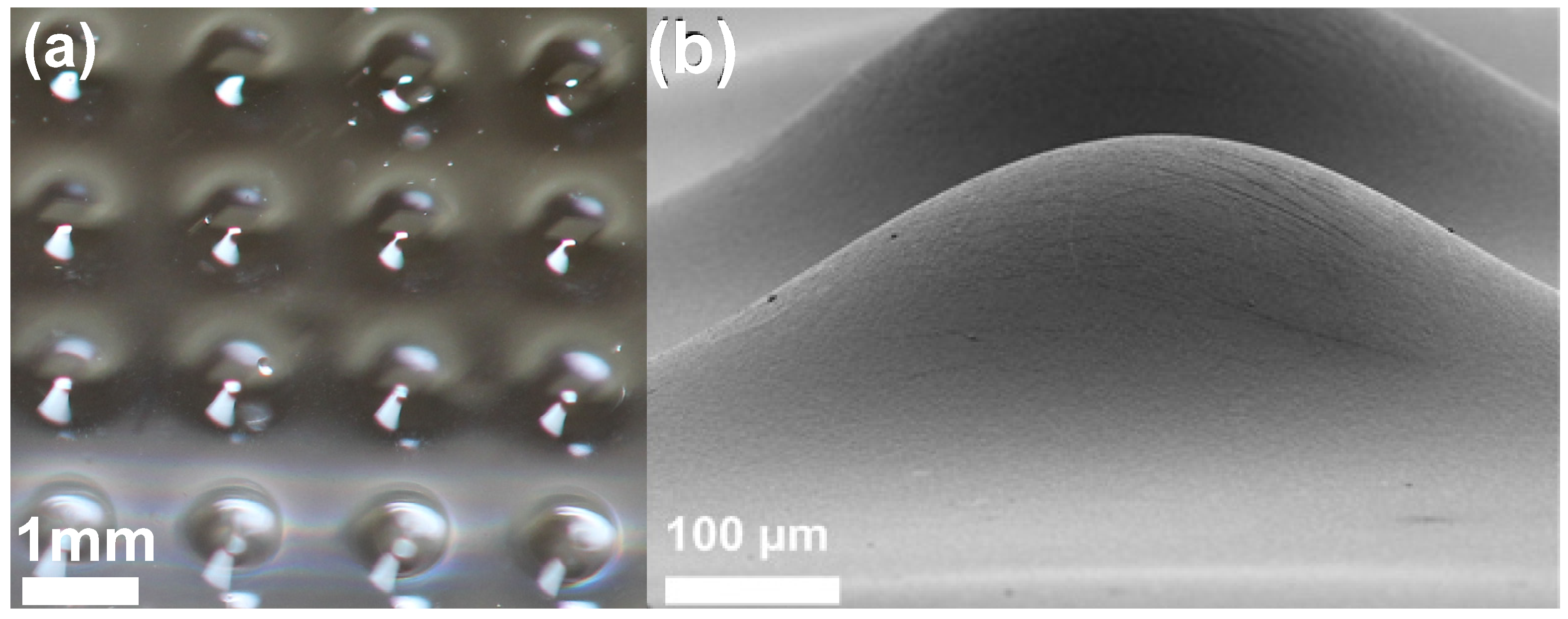
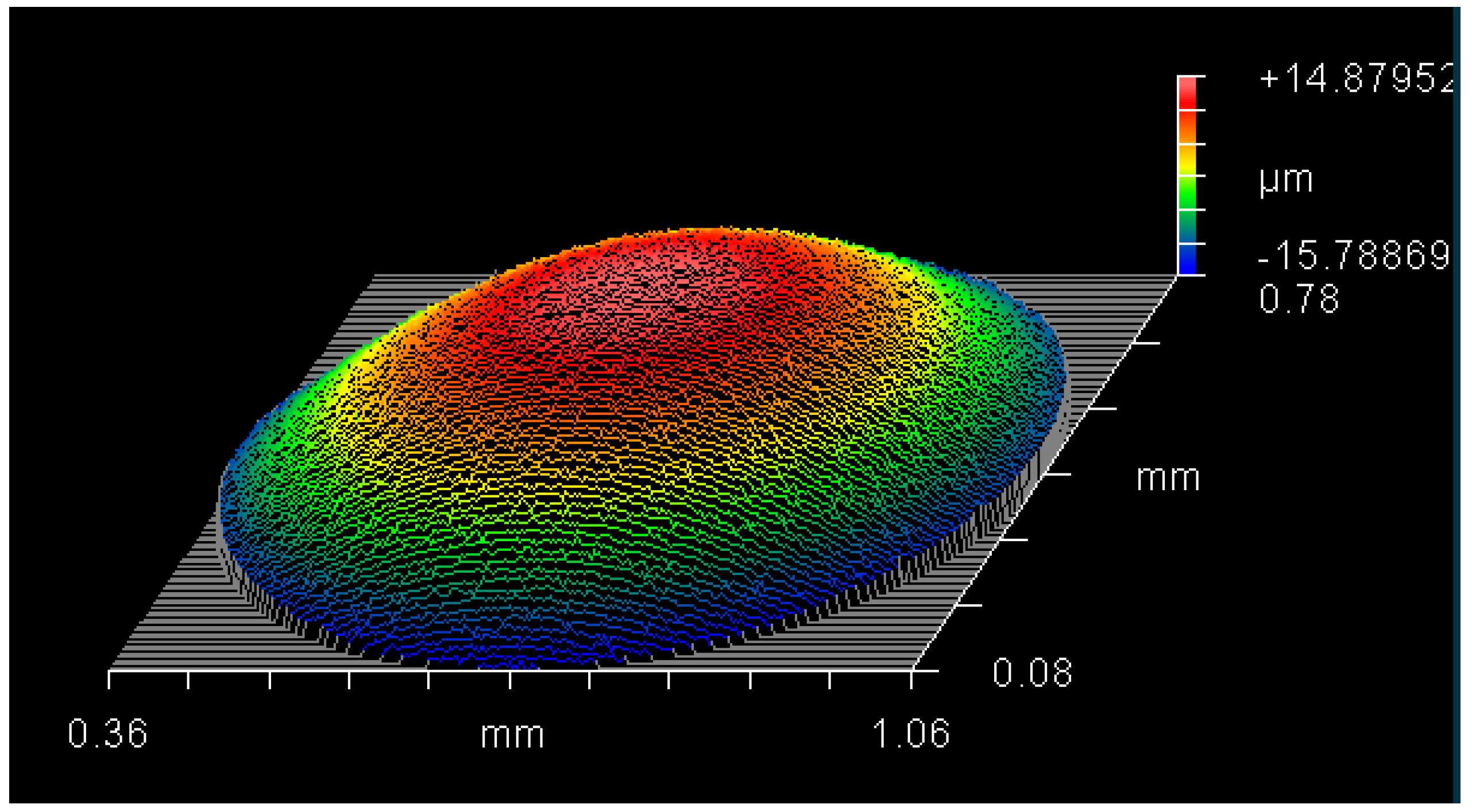
3.1. Microlens Analysis

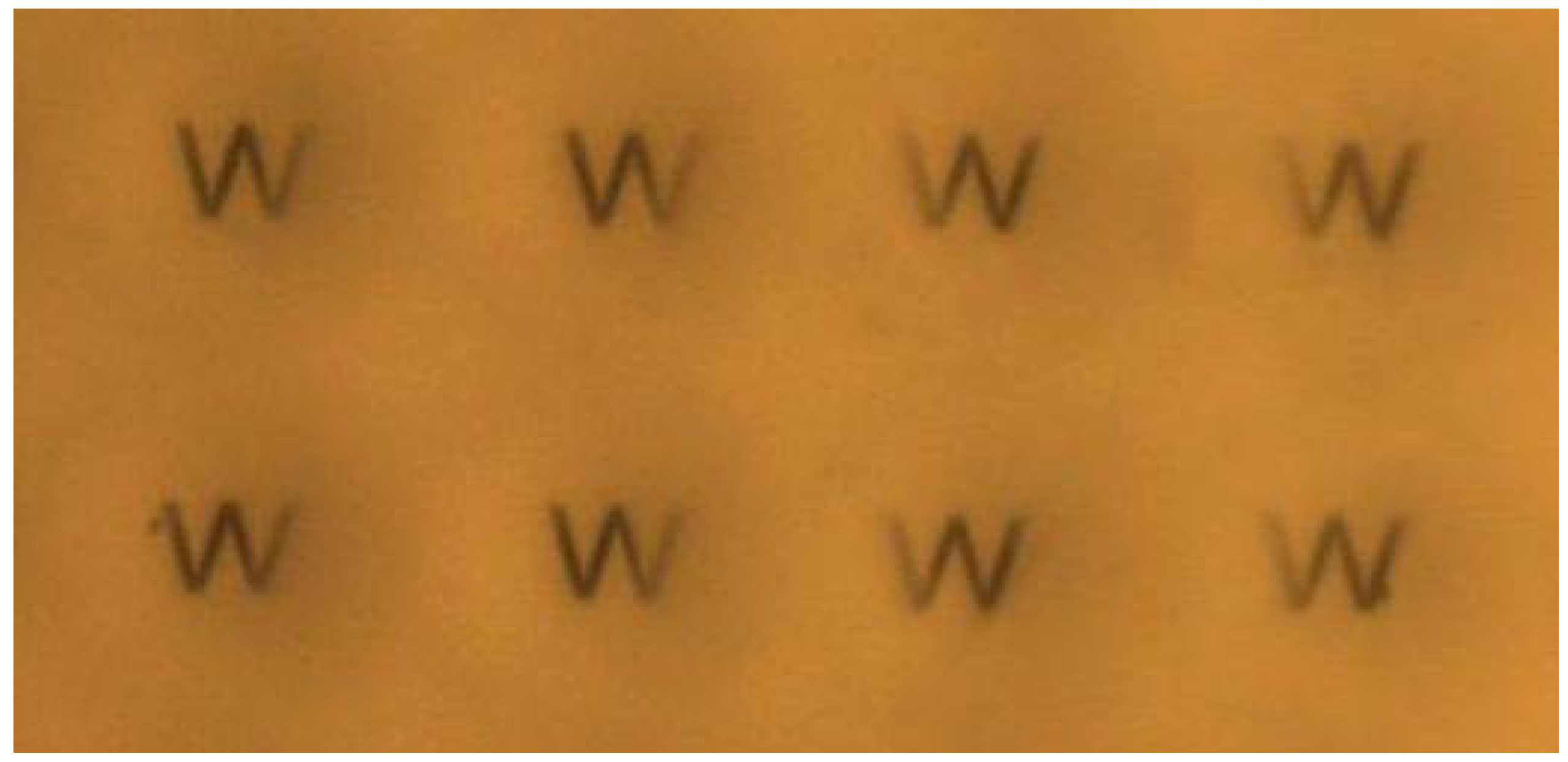
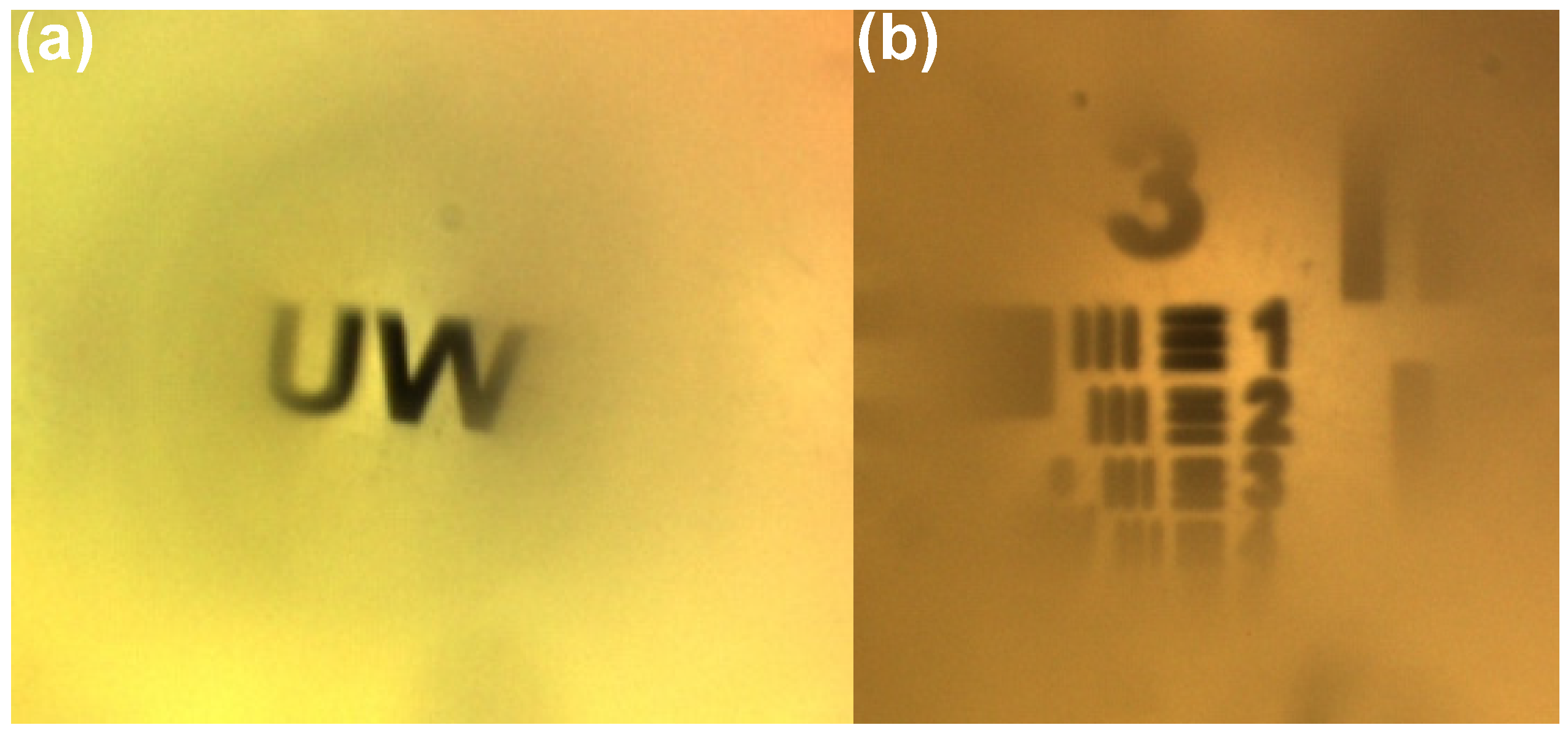
3.2. Image Analysis


| Parameter | 0.7-mm | 1-mm |
|---|---|---|
| Focal length (mm) | 5.417 | 2.94 |
| Spherical aberration (µm) | 2.85 | 31.276 |
| Resolution (lp/mm) | 8.98 | 7.13 |
| Roughness (nm) | 204 | 320 |
| Parameter | Shrinkage (h) | |||
|---|---|---|---|---|
| 9 | 12 | 18 | 24 | |
| Focal length (mm) | 39.57 | 16.2 | 11.55 | 5.63 |
| Spherical aberration (µm) | 0.634 | 2.147 | 3.59 | 9.66 |
| Roughness (nm) | 110 | 204 | 255 | 187 |
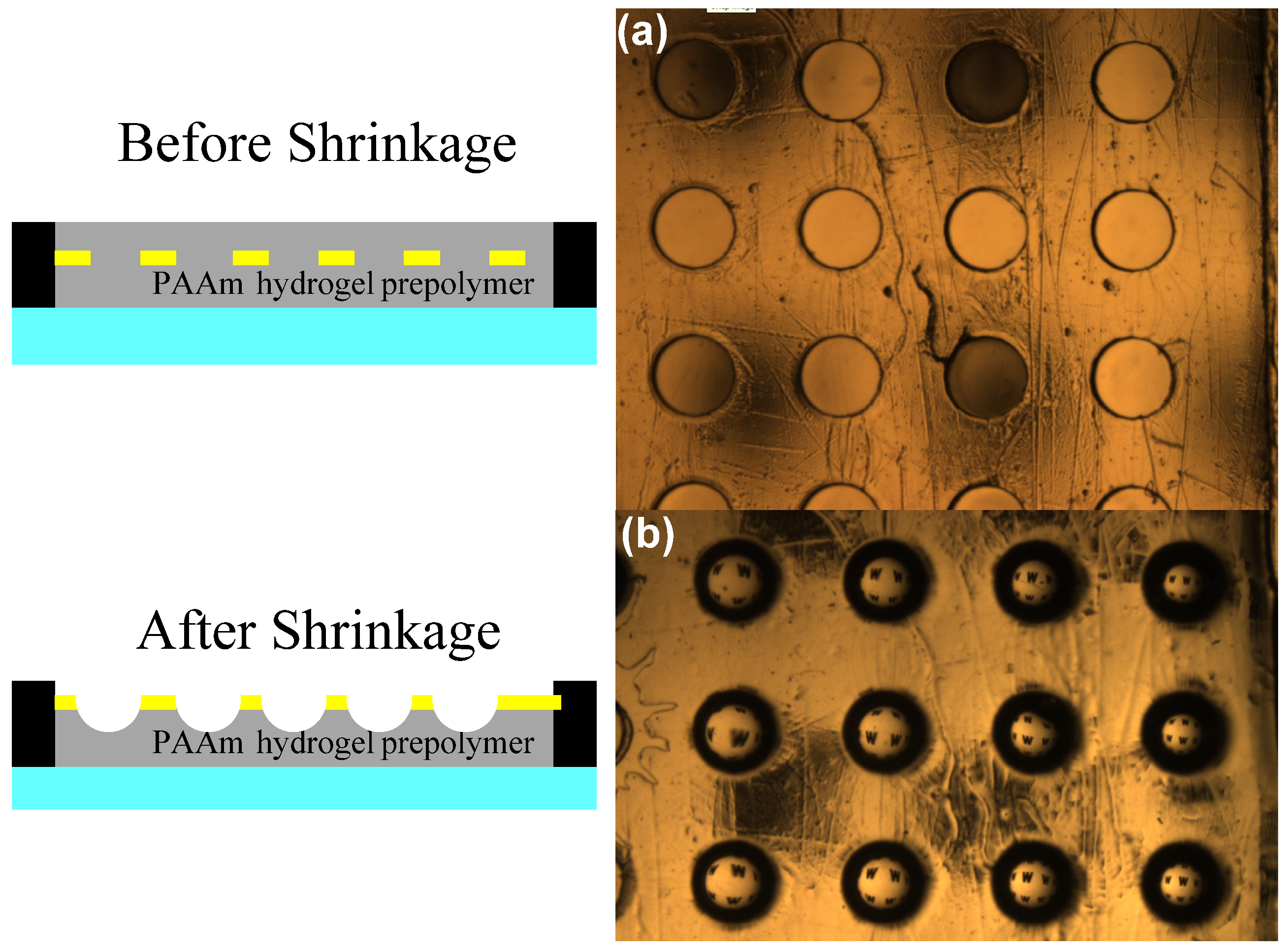
3.3. Shrinkage


3.4. Rehydration
3.5. Compound Eye

3.6. Aperture Limitation
3.7. Time Sensitive Fabrication Process
4. Conclusions
Acknowledgments
Author Contributions
Conflicts of Interest
References
- Yang, H.; Chao, C.-K.; Wei, M.-K.; Lin, C.-P. High fill-factor microlens array mold insert fabrication using a thermal reflow process. J. Micromech. Microeng. 2004, 14, 1197–1204. [Google Scholar] [CrossRef]
- Beihl, S.; Danzebrikn, R.; Oliveira, P.; Aegerter, M.A. Refractive microlens fabrication by ink jet process. J. Sol-Gel Sci. Technol. 1998, 13, 177–182. [Google Scholar] [CrossRef]
- Rogers, J.D.; Karkkainen, A.H.O.; Tkaczyk, T.; Rantala, J.T.; Descour, M.R. Realization of refractive microoptics through grayscale lithographic patterning of photosensitive hybrid glass. Opt. Express 2004, 12, 1294–1303. [Google Scholar] [CrossRef]
- Yu, X.; Wang, Z.; Han, Y. Microlenses fabricated by discontinuous dewetting and soft lithography. Microelectron. Eng. 2008, 85, 1878–1881. [Google Scholar] [CrossRef]
- Huang, L.-C.; Lin, T.-C.; Huang, C.-C.; Chao, C.-Y. Photopolymerized self-assembly microlens arrays based on phase separation. Soft Matter 2011, 7, 2812–2816. [Google Scholar] [CrossRef]
- Daly, D. Microlens Arrays; Taylor and Francis: New York, NY, USA, 2001. [Google Scholar]
- Park, S.; Jeong, Y.; Kim, J.; Choi, K.; Kim, H.C.; Chung, D.S.; Chun, K. Fabricaton of poly(dimethylsiloxane) microlens for laser-induced fluorescence detection. Jpn. J. Appl. Phys. Part 1 Regul. Pap. Short Notes Rev. Pap. 2006, 45, 5614–5617. [Google Scholar]
- Zeng, X.; Jiang, H. Polydimethylsiloxane microlens arrays fabricated through liquid-phase photopolymerization and molding. J. Microelectromech. Syst. 2008, 17, 1210–1217. [Google Scholar] [CrossRef]
- Kim, H.-K.; Yun, K.-S. Fabrication of PDMS Microlenses with Various Curvatures Using a Water-Based Molding Method. In Proceedings of the 12th International Conference on Miniaturized Systems for Chemistry and Life, San Diego, CA, USA, 12–16 October 2008; pp. 994–996.
- Yu, H.; Zhou, G.; Chau, F.S.; Lee, F. Fabrication and characterization of PDMS microlenses based on elastomeric molding technology. Opt. Lett. 2009, 34, 3454–3456. [Google Scholar] [CrossRef]
- Qu, P.; Chen, F.; Liu, H.; Yang, Q.; Lu, J.; Si, J.; Wang, Y.; Hou, X. A simple route to fabricate artificial compound eye structures. Opt. Express 2012, 20, 5775–5782. [Google Scholar] [CrossRef]
- Jeong, K.-H.; Kim, J.; Lee, L.P. Biologically inspired artificial compound eyes. Science 2006, 312, 557–561. [Google Scholar] [CrossRef]
- Zhu, D.; Zeng, X.; Li, C.; Jiang, H. Focus-tunable microlens arrays fabricated on spherical surfaces. J. Microelectromech. Syst. 2011, 20, 389–395. [Google Scholar] [CrossRef]
- Ko, H.C.; Stoykovich, M.P.; Song, J.; Malyarchuk, V.; Choi, W.M.; Yu, C.-J.; Geddes, J.B.; Rogers, J.A. A hemispherical electronic eye camera based on compressible silicon optoelectronics. Nature 2008, 454, 748–753. [Google Scholar]
- He, Q.; Liu, J.; Yang, B.; Dong, Y.; Yang, C. Fabrication and characterization of biologically inspired curved-surface artificial compound eyes. J. Microelectromech. Syst. 2013, 22, 4–6. [Google Scholar] [CrossRef]
- Radtke, D.; Duparré, J.; Zeitner, U.D.; Tünnermann, A. Laser lithographic fabrication and characterization of a spherical artificial compound eye. Opt. Express 2007, 15, 3067–3077. [Google Scholar] [CrossRef]
- Das, A.L.; Mukherjee, R.; Katiyer, V.; Kulkarni, M.; Ghatak, A.; Sharma, A. Generation of sub-micrometer-scale patterns by successive miniaturization using hydrogels. Adv. Mater. 2007, 19, 1943–1946. [Google Scholar] [CrossRef]
- Dong, L.; Agarwal, A.K.; Beebe, D.J.; Jiang, H. Adaptive liquid microlenses activated by stimuli-responsive hydrogels. Nature 2006, 442, 551–554. [Google Scholar] [CrossRef]
- Agarwal, A.K.; Beebe, D.J.; Jiang, H. Integration of polymer and metal microstructures using liquid-phase photopolymerization. J. Micromech. Microeng. 2006, 16, 332–340. [Google Scholar] [CrossRef]
- Sridharamurthy, S.S.; Dong, L.; Jiang, H. A microfluidic chemical/biological sensing system based on membrane dissolution and optical absorption. Meas. Sci. Technol. 2007, 18, 201–207. [Google Scholar] [CrossRef]
- Smooth-on Corp Homepage. Available online: http://www.smooth-on.com (accessed on 5 April 2013).
- Aldalali, B.; Zhu, D.; Jiang, H. Fabrication of Polydimethylsiloxane Microlens Arrays on Curved Surfaces. In Proceedings of the 16th International Conference on Optical MEMS and Nanophotonics Istanbul, Istanbul, Turkey, 2011; pp. 239–240.
- Zappe, H. Micro-optics: A micro-tutorial. Adv. Opt. Technol. 2012, 1, 117–126. [Google Scholar]
- Nussbaum, P.; Volkel, R.; Herzig, H.P.; Eisner, M.; Haselbeck, S. Design, fabrication and testing of microlens arrays for sensors and microsystems. Pure Appl. Opt. 1997, 6, 617–636. [Google Scholar] [CrossRef]
- Chang-Yen, D.A.; Eich, R.K.; Gale, B.K. A monolithic PDMS waveguide system fabricated using soft-lithography techniques. J. Lightwave Technol. 2005, 23, 2088–2093. [Google Scholar] [CrossRef]
- Huang, N.; Lee, R.; Li, S. Engineering of aligned skeletal muscle by micropatterning. Am. J. Transl. Res. 2010, 2, 43–55. [Google Scholar]
- Zeng, X.; Jiang, H. Microlenses: Properties, Fabrication and Liquid Lenses; Taylor and Francis: Boca Raton, FL, USA, 2013. [Google Scholar]
© 2014 by the authors; licensee MDPI, Basel, Switzerland. This article is an open access article distributed under the terms and conditions of the Creative Commons Attribution license (http://creativecommons.org/licenses/by/3.0/).
Share and Cite
Aldalali, B.; Kanhere, A.; Fernandes, J.; Huang, C.-C.; Jiang, H. Fabrication of Polydimethylsiloxane Microlenses Utilizing Hydrogel Shrinkage and a Single Molding Step. Micromachines 2014, 5, 275-288. https://doi.org/10.3390/mi5020275
Aldalali B, Kanhere A, Fernandes J, Huang C-C, Jiang H. Fabrication of Polydimethylsiloxane Microlenses Utilizing Hydrogel Shrinkage and a Single Molding Step. Micromachines. 2014; 5(2):275-288. https://doi.org/10.3390/mi5020275
Chicago/Turabian StyleAldalali, Bader, Aditi Kanhere, Jayer Fernandes, Chi-Chieh Huang, and Hongrui Jiang. 2014. "Fabrication of Polydimethylsiloxane Microlenses Utilizing Hydrogel Shrinkage and a Single Molding Step" Micromachines 5, no. 2: 275-288. https://doi.org/10.3390/mi5020275