Fast-Response Liquid Crystal Microlens

1
CREOL, The College of Optics and Photonics, University of Central Florida, 4000 Central Florida Blvd, Orlando, FL 32816, USA
2
National Engineering Lab for TFT-LCD Materials and Technologies, Department of Electronic Engineering, Shanghai Jiao Tong University, Shanghai 200240, China
3
Department of Polymer-Nano Science and Technology, Chonbuk National University, Jeonju, Jeonbuk 561-756, Korea
*
Author to whom correspondence should be addressed.
Micromachines 2014, 5(2), 300-324; https://doi.org/10.3390/mi5020300
Submission received: 4 May 2014
/
Revised: 23 May 2014
/
Accepted: 27 May 2014
/
Published: 3 June 2014
(This article belongs to the Special Issue Microlenses)
Abstract
:Electrically tunable liquid crystal microlenses have attracted strong research attention due to their advantages of tunable focusing, voltage actuation, low power consumption, simple fabrication, compact structure, and good stability. They are expected to be essential optical devices with widespread applications. However, the slow response time of nematic liquid crystal (LC) microlenses has been a significant technical barrier to practical applications and commercialization. LC/polymer composites, consisting of LC and monomer, are an important extension of pure LC systems, which offer more flexibility and much richer functionality than LC alone. Due to the anchoring effect of a polymer network, microlenses, based on LC/polymer composites, have relatively fast response time in comparison with pure nematic LC microlenses. In addition, polymer-stabilized blue phase liquid crystal (PS-BPLC) based on Kerr effect is emerging as a promising candidate for new photonics application. The major attractions of PS-BPLC are submillisecond response time and no need for surface alignment layer. In this paper, we review two types of fast-response microlenses based on LC/polymer composites: polymer dispersed/stabilized nematic LC and polymer-stabilized blue phase LC. Their basic operating principles are introduced and recent progress is reviewed by examples from recent literature. Finally, the major challenges and future perspectives are discussed.

1. Introduction
Liquid crystals (LCs) exhibit unique material properties ranging between those of conventional isotropic liquids and solid-state crystals. The operation mechanisms of an LC device can be roughly grouped into two categories: molecular reorientation under the influence of an electric field [1] and field-induced mechanical deformation of the droplet shape [2]. The former was pioneered by Schadt and Helfrich, enabling today’s liquid crystal displays (LCDs), phase modulators, adaptive lenses, optical switches, and other photonic devices [1].
Since the first concept was demonstrated in 1977 by Bricot [3], adaptive LC lenses have attracted strong research attention due to their advantages of tunable focusing, voltage actuation, low power consumption, simple fabrication, compact structure, and good stability. They are expected to be essential optical devices with widespread applications. Generally speaking, LC lenses can be divided into two categories according to their aperture size: those with a large aperture size (>1 mm) are suitable for portable devices, such as pico projectors, imaging system for cell phones, endoscopic system, and ophthalmic lenses [4,5,6,7,8], while those with a small aperture size (<1 mm) are suitable for microlens arrays and their applications include image processing [9,10,11,12,13,14,15,16,17,18,19], optical communication [20,21], lab on a chip, switchable 2D/3D displays [22,23], etc. The progresses of LC lenses with a large aperture size have been reviewed by Fowler et al. in 1990 [24] and more recently by Lin et al. in 2011 [25]. In the present review article, we focus on LC microlenses, especially those with fast response times.
Most LC lenses/microlenses developed thus far employ nematic LCs (NLCs), which offer a large birefringence to achieve a short focal length. Two major technical challenges have severely limited their practical applications and commercialization: polarization dependency and slow response time (several seconds or hundreds of milliseconds). The former can be solved by using residual phase modulations [26,27], and optical isotropic materials, such as blue phase LC [28,29,30,31,32,33,34], double-layered structure [35,36,37], or axially symmetric photoalignment [38]. Due to the intrinsic speed of NLCs, the response time of a LC microlens is usually in the order of 100 ms, which is obviously not fast enough for image processing, optical communication, etc. Several approaches have been proposed to improve the response time. Dual frequency LCs (DFLCs), which exhibit a positive dielectric anisotropy (Δε) at low frequencies and negative Δε at high frequencies, have been adopted to speed up both rise and decay times of an LC device by controlling the applied frequency [36,39,40]. However, the driving scheme is relatively complicated, and dielectric heating may shift the crossover frequency and lead to performance instability at high frequency operation [41]. Surface-stabilized ferroelectric LCs (SSFLCs) can be switched in 100 μs and the response time of SSFLC microlenses is approximately 1000 times faster than that of nematic devices, however, they are only good for binary optical modulation because of the hysteresis characteristics [42,43]. Microlenses based on chiral sematic A (SmA*) LCs could tune the focal length in several microseconds, which is 10× to 1000× faster than that using SSFLCs or NLCs, respectively [44], but the alignment of LC molecules is not stable. In comparison to the abovementioned approaches, microlenses based on LC/polymer composites provide a relatively fast response time, continuous variable optical power, simple fabrication, and driving scheme, as well as good mechanical stability. These attractive features make them more promising for practical applications. In addition, polymer-stabilized blue phase liquid crystal (BPLC) based on the Kerr effect [45,46,47,48,49,50] is emerging as a promising candidate for new photonics applications. The major attractions of BPLC are twofold: (1) submillisecond response time due to its self-assembled nanostructure [33,48,51], which is ~10× faster than that of NLCs and (2) free of a molecular alignment layer, which means a simpler fabrication process.
In this review article, we first explain the basic principles of LC microlenses. Then, we illustrate the recent progress on the development of fast-response LC microlenses based on LC/polymer composites by the examples from recent literature, covering topics of polymer-dispersed/stabilized nematic LC microlenses and BPLC microlenses. For each type of microlens, the cell structure, lens performance, focal length tenability, and dynamic response are described, as well as their advantages and disadvantages. Challenges and future perspectives are also discussed.
2. Polymer-Dispersed/Stabilized Nematic Liquid Crystal Microlens
2.1. Principles
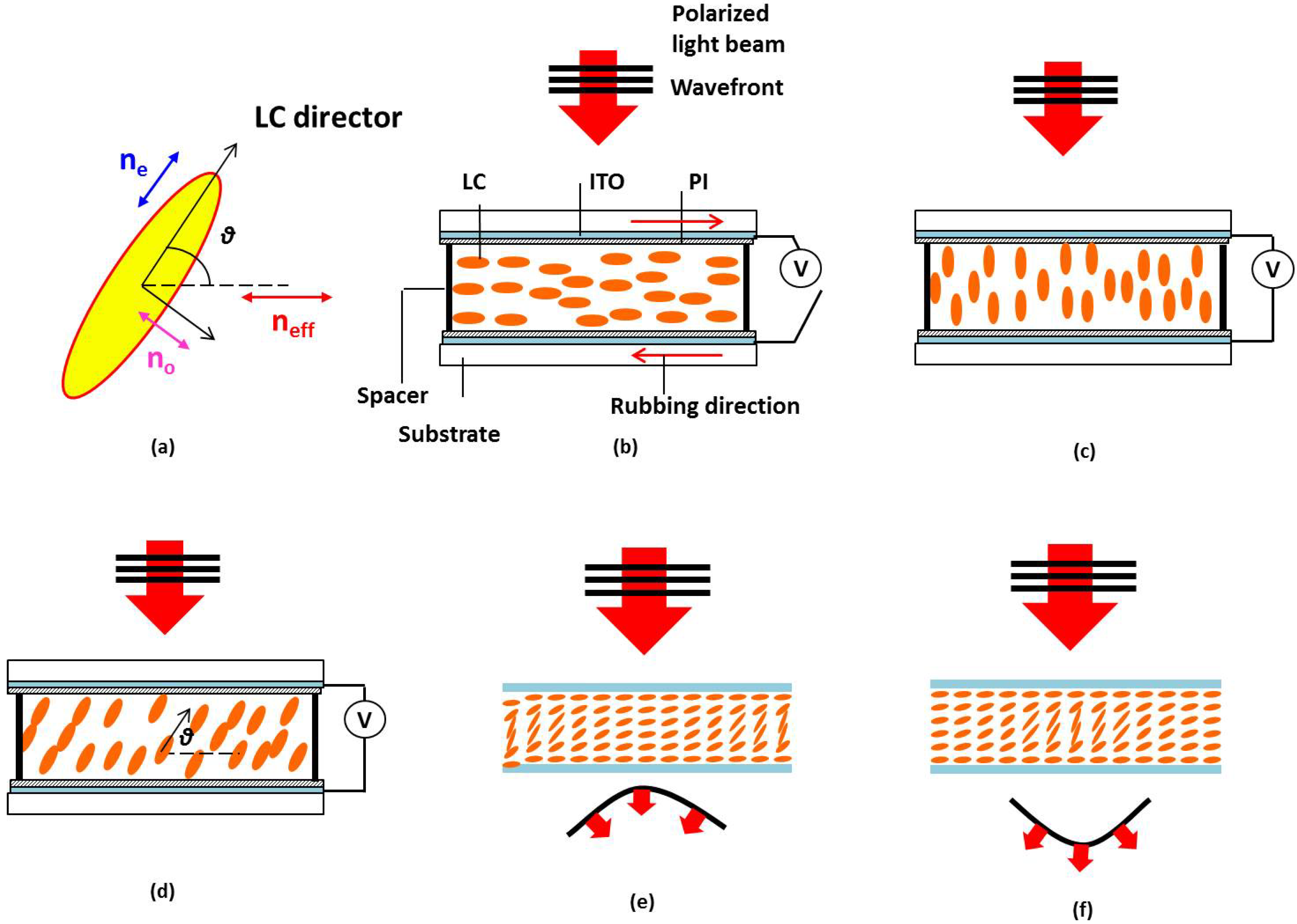
Nematic LCs are rod-like molecules, which exhibit optical and dielectric anisotropies due to their anisotropic molecular structures. When properly aligned in an LC cell, their long axes are approximately parallel to each other, and this averaged alignment direction is called LC director, as shown in Figure 1a [52]. Light polarized along the LC director (e-ray, polarization direction is represented by blue arrow) sees extraordinary refractive index ne, while that polarized perpendicular (o-ray, polarization direction is represented by pink arrow) to the LC director sees ordinary refractive index no. Then, if the light is polarized at a θ angle with respect to the director (represented by red arrow), it sees an effective refractive index neff, expressed as:
![Micromachines 05 00300 i001]() The birefringence (optical anisotropy) of the LC is defined as:
and the dielectric anisotropy is defined as:
where ε∕∕ and ε⊥ are the dielectric constant ( or relative permittivity) along and perpendicular to the LC director, respectively.
The birefringence (optical anisotropy) of the LC is defined as:
and the dielectric anisotropy is defined as:
where ε∕∕ and ε⊥ are the dielectric constant ( or relative permittivity) along and perpendicular to the LC director, respectively.

Δn = ne − no
Δε = ε∕∕ − ε⊥
In a typical cell, LC passing the cell, where d is the cell gap. When a sufficiently high voltage is applied to the indium tin oxide (ITO) electrodes, the LC directors will be reoriented material is sandwiched between two substrates coated with electrodes (e.g., indium tin oxide, ITO) and surface alignment layers (e.g., polyimide, PI) [53]. Buffed PI introduces the alignment of LC directors while spacers control the cell gap. Figure 1b shows the schematic structure of a homogeneous LC cell, where the top and bottom substrates are rubbed in anti-parallel directions and LC directors are aligned along the substrates in the static state. Let us assume the normally incident light is polarized along the rubbing direction. It will experience an optical path of L = dne after in vertical direction and the optical path becomes L = dno (Figure 1b) If the voltage is not high enough and the LC directors are only reoriented by a θ angle (Figure 1c), the corresponding optical path is ![Micromachines 05 00300 i002]() , where neff(θ) is the effective refractive index expressed by Equation (1). If the LC molecules, located at different positions, could be controlled to have various reorientation angles, then the light will experience various refractive indices accordingly, as shown in Figure 1d. Here, the light incident on the center and border experience neff(θ) and ne, respectively, the optical path difference (OPD) between the center and border can be expressed as:
At a given wavelength (λ), the corresponding phase difference ΔØ is:
, where neff(θ) is the effective refractive index expressed by Equation (1). If the LC molecules, located at different positions, could be controlled to have various reorientation angles, then the light will experience various refractive indices accordingly, as shown in Figure 1d. Here, the light incident on the center and border experience neff(θ) and ne, respectively, the optical path difference (OPD) between the center and border can be expressed as:
At a given wavelength (λ), the corresponding phase difference ΔØ is:
![Micromachines 05 00300 i003]()
 , where neff(θ) is the effective refractive index expressed by Equation (1). If the LC molecules, located at different positions, could be controlled to have various reorientation angles, then the light will experience various refractive indices accordingly, as shown in Figure 1d. Here, the light incident on the center and border experience neff(θ) and ne, respectively, the optical path difference (OPD) between the center and border can be expressed as:
OPD = d(neff(θ) − no)

Such an effect is equivalent to an isotropic medium with different thickness. It is well known that if the surface of the isotropic medium is polished with a spherical shape, then it functions as a lens. Similarly, if the LC layer exhibits a lens-like gradient refractive index distribution or phase profile, then it has a lens characteristic. For example, in Figure 1e, the normally incident e-ray experiences a gradually increased refractive index distribution from the border to center, and the LC layer functions as a positive lens. Vice versa, the LC layer would function as a negative lens if the refractive index gradually decreases from the border to center, as shown in Figure 1f. Gradient refractive index distribution or phase profile within the LC layer forms the foundation of an LC lens. Various approaches for fabricating LC microlens array have been proposed. The common is to create a gradient refractive index distribution among LC directors either by an inhomogeneous electric field [9,10,15,16,17,20,22,23,54] or by an inhomogeneous LC morphology [11,12,13,14,18,19,21,55,56].
Focal length (or optical power) and response time are two very important factors. The focal length is related to the lens radius (r), refractive index difference between center and boarder of the lens (Δn), and thickness of LC layer (d) as [53]:
![Micromachines 05 00300 i004]() The response time (decay and rise) of a nematic LC lens is determined by the visco-elastic coefficient (γ/K), LC layer thickness of (d), applied voltage (V), and threshold voltage (Vth) as [52]:
The response time (decay and rise) of a nematic LC lens is determined by the visco-elastic coefficient (γ/K), LC layer thickness of (d), applied voltage (V), and threshold voltage (Vth) as [52]:
![Micromachines 05 00300 i005]()
![Micromachines 05 00300 i006]()


Although the rise time can be greatly shortened by applying an overdrive voltage, the decay time is still determined by the restoring elastic torque. This problem gets even worse as the wavelength increases, e.g., infrared region, since a thicker cell gap is required to compensate the longer wavelength and lower birefringence. To obtain a short focal length, we could increase dΔn or reduce the lens aperture. Most of high birefringence LCs have Δn ~0.4 [57]. Some ultra-high Δn (>0.6) LCs have been developed, but their large viscosity leads to a slow response time [58]. Similarly, increasing the LC layer thickness also causes a sluggish response time, as Equation (7) indicates.
Figure 1.
Operation principle of a nematic LC lens: (a) LC molecular and polarization dependent refractive index; (b) schematic structure of a homogeneous LC cell, the incident light sees ne; (c) LC directors are reoriented along the electric field and the incident light sees no; (d) LC directors are reoriented by a θ angle and the incident light sees neff(θ); (e) positive LC lens, and (f) negative LC lens.

LC/polymer composites, consisting of LC and polymer, are an important extension of pure LC systems, which offer more flexibility and much richer functionality than LC alone. Depending on the monomer concentration, LC/polymer composites can be divided into three major categories: polymer-dispersed LCs (PDLCs) [59], polymer-stabilized LCs (PSLCs) [60], and polymer-network LCs (PNLCs) [61]. PDLC consists of a higher percentage of monomer (>20 wt %), while PSLC consists of a lower percentage of monomer (<10 wt %), PNLC consists of a medium percentage of monomer (10 wt % ~ 20 wt %). Due to the anchoring effect of polymer network, microlenses, based on PDLC/PSLC/PNLC, offer a relatively fast response time in comparison with pure nematic LC microlenses. Nevertheless, the domain size needs to be carefully controlled to avoid scattering.
2.2. Microlens Using Nanosized Polymer-Dispersed Liquid Crystal Droplets
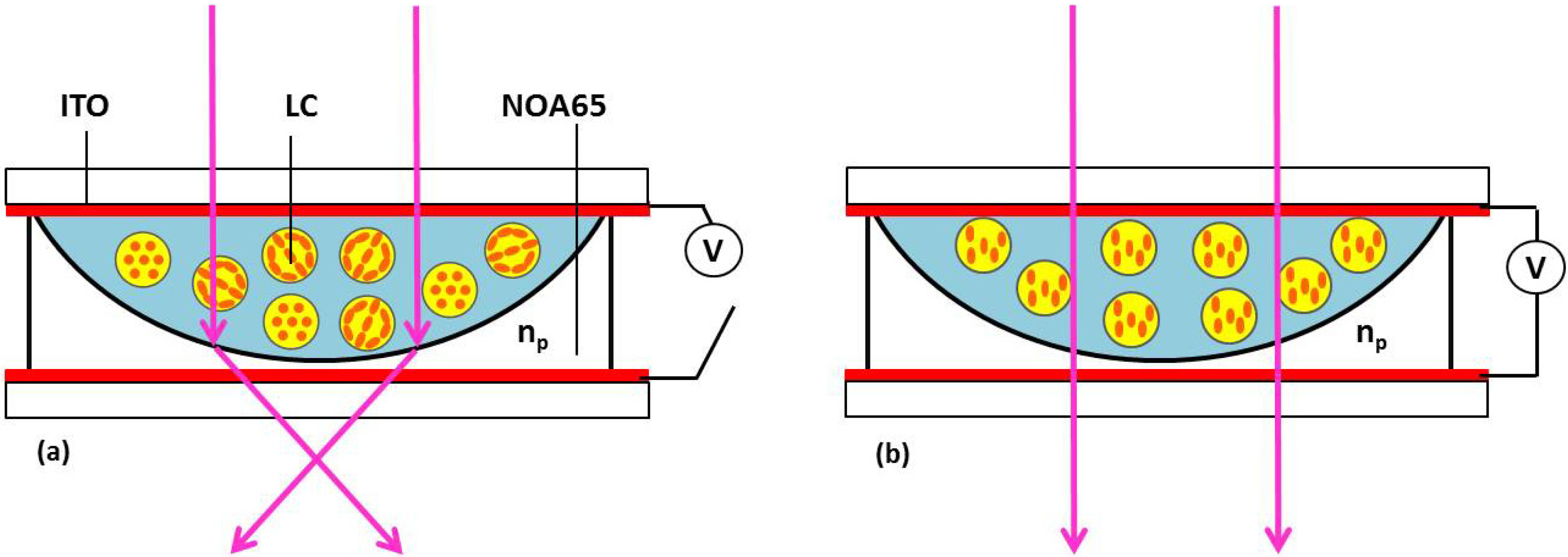
In 2005, Ren et al. demonstrated a fast-response microlens array using nanosized PDLC droplets [54], as Figure 2 shows. UV-curable monomer NOA65 is first molded to form plano-concave microlens arrays on the bottom ITO substrate. The plano-concave cavities are filled with nano-PDLC material, which consists of 35 wt % NOA65 (np = 1.524) and 65 wt % Merck nematic LC E48 (no = 1.523, Δn = 0.23). The ordinary refractive index of the LC material matches well with that of the polymer matrix. After UV curing at 15 mW·cm−2 and 50 °C for 30 min, a saturated phase separation between NOA65 and E48 is obtained, and LC droplets are uniformly dispersed in polymer matrix. In the voltage-off state, the LC droplets are randomly oriented, and the average refractive index of the nano-PDLC is larger than that of the NOA65 (np = 1.524), and the incident light can be focused (Figure 2a). At the voltage-on state, the LC directors are reoriented along the electric field direction, and effective refractive index in the plane perpendicular to the electric field is decreased. According to Equation (6), the focal length increases. When the voltage is high enough, the focusing effect will disappear since all the LC directors have been reoriented along the electric field (Figure 2b). For the LC microlens with a 450 µm aperture and 45 µm cell gap, its focal length was continuously tunable from 3.3 cm to 3.5 cm (λ = 633 nm) when the voltage increased to 200 Vrms. The τrise (from focusing to less-focusing) and τfall (from less-focusing to focusing) were measured to be ~0.25 ms and ~0.15 ms, under 200 Vrms square pulses. Due to the randomly oriented LC droplets in the polymer matrix, such microlenses are polarization independent. Moreover, the LC droplet size is smaller than a visible wavelength, thus it doesn’t scatter light. However, the operating voltage is quite high and it is difficult to further tune the focal length to infinity even the voltage keeps increasing. Besides, in PDLC microlens the refractive index difference between the microlens center and border is relatively small, i.e., Δn = cΔn/3, where Δn is the LC birefringence and c is the LC concentration. In this microlens array, the theoretical δn is only ~0.027, which is much smaller than the LC birefringence (Δn = 0.23). As a result, the dynamic range is rather limited.
Figure 2.
Side view of the nano-PDLC lens in the: (a) voltage-off state; and (b) voltage-on state.

2.3. Polymer-Stabilized Liquid Crystal (PSLC) Microlens
2.3.1. PSLC Microlens Using a Patterned Photomask
To lower the operating voltage, increase the phase shift and improve the dynamic response time during focus change, PSLC is a feasible approach [60]. Different from nano-PDLC, monomers used in PSLC usually have a rod-like structure with a reactive double bond at both sides, similar to the structure of nematic LC molecules. In addition, the monomer concentration in PSLC is 10 wt % or less. When an LC/monomer mixture is filled into the cell, both LC molecules and monomers will exhibit the same alignment property, if the inner surface of the substrate is properly rubbed. Under UV exposure, the double bonds of the monomer are opened and the molecules are linked together, forming a stable polymer network [53].
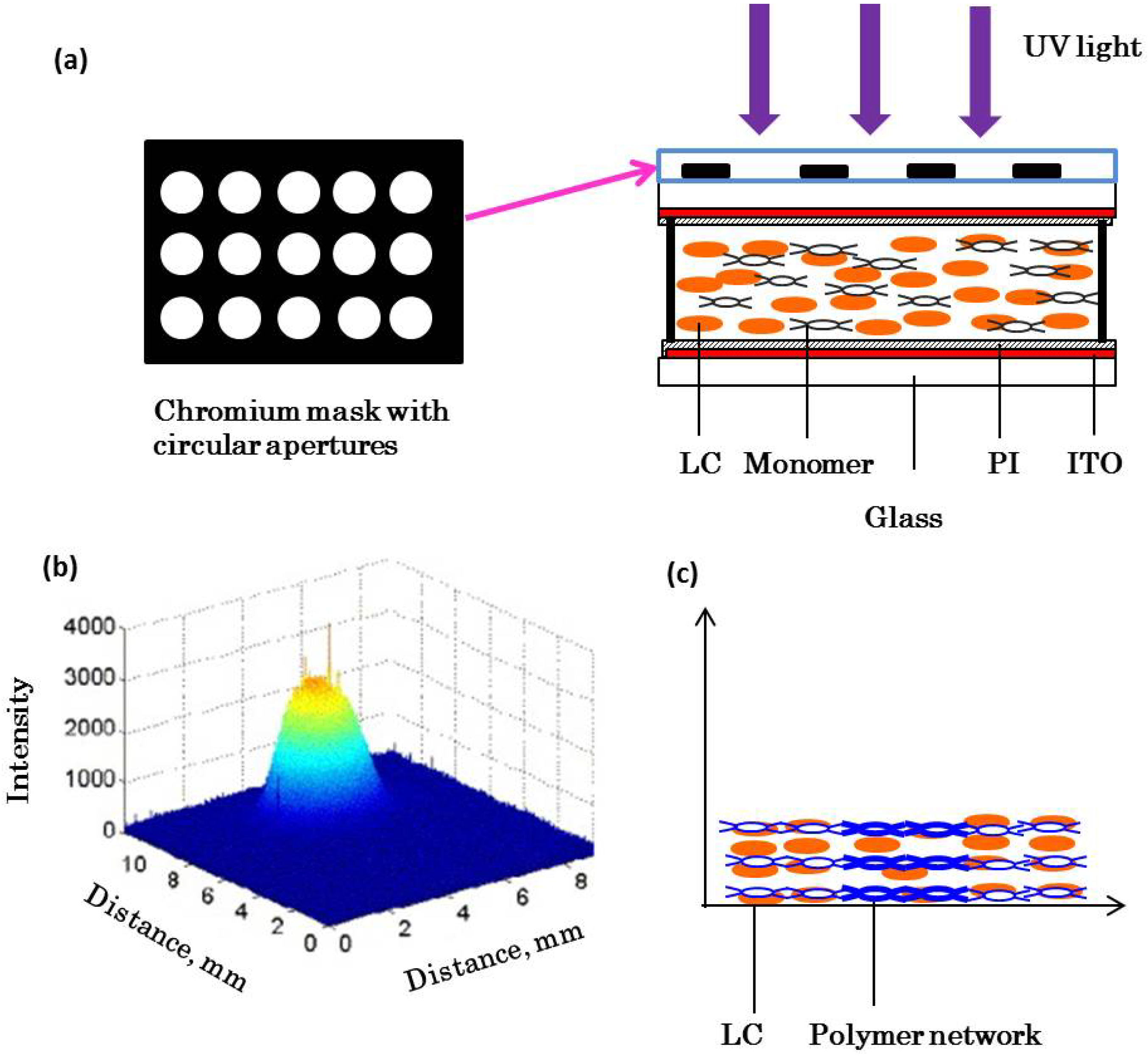
A PSLC microlens array is usually prepared through a spatially inhomogeneous UV exposure, which can be generated by two methods: (1) UV laser beam with a Gaussian-shaped profile [55]; (2) a uniform UV laser beam passing through an optical density filter, e.g., hole-array patterned photomask [56,61,62]. The latter is much simpler and more suitable for making microlens array.
Figure 3.
(a) Fabrication setup of PSLC microlens array; (b) recorded UV intensity profile after passing through Ø25 µm hole and (c) formed polymer network after UV exposure.
Figure 3.
(a) Fabrication setup of PSLC microlens array; (b) recorded UV intensity profile after passing through Ø25 µm hole and (c) formed polymer network after UV exposure.

Figure 3a depicts the fabrication setup of PSLC microlens array using a hole-array patterned photomask [56]. The LC/monomer mixture consists of 3 wt % BAB6 monomer and 97 wt % E48 nematic LC (Δn = 0.231 at λ = 589 nm and T = 20 °C), as well as a small amount of photoinitiators. The cell gap and substrate thickness are 15 μm and 1.1 mm, respectively. The substrates are rubbed in anti-parallel directions. A chromium photomask having hole-array apertures is placed on the top a substrate. The diameter of each hole is 25 μm. When the UV beam (λ = 365 nm) passes through the holes, diffraction appears. Figure 3b shows the measured UV intensity profile after the beam passing through the single hole. The formed diffraction pattern consists of a series of rings, but most of light energy concentrates on the 0th order ring, which presents a parabolic-like profile. When the LC/monomer mixture is exposed to such a UV intensity distribution, the stronger intensity in the central region will accelerate the polymerization rate and form a denser polymer network (i.e., the polymer-rich region). On the contrary, the weaker intensity at the borders will have a slower polymerization rate and form a looser polymer network (i.e., LC-rich region). Therefore, a centro-symmetric inhomogeneous polymer network is formed, as shown in Figure 3c. The polymer-rich region exhibits a higher threshold voltage than that of the border LC-rich region. Therefore, the LC molecules on the border are reoriented first under a uniform electric field. This gradient refractive index distribution makes the PSLC function like a positive microlens. At V = 0, the PSLC exhibits a homogeneous alignment and no focusing effect occurs. As the voltage increases, the focal length first decreases to ~2 cm at ~5 Vrms, and then increases again. Because at a higher voltage, the LC molecules in the polymer-rich and LC-rich regions are all reoriented towards the electric field, the gradient refractive index profile is gradually flattened. The focal length was measured to be ~3.3 cm at 20 Vrms and response time <20 ms. Theoretically, a sufficiently high voltage could reorient all the LC molecules along the electric field, leading to an infinity focal length. However, LC molecules at the border of the microlens experience the weakest stabilization; thus, the microlens aperture has a tendency to shrink at high voltage. On the other hand, LC molecules in the center may be strongly anchored by the polymer network and cannot contribute to the phase change. In this PSLC microlens array, the focal length gradually saturates as the voltage exceeds 10 Vrms and cannot be further tuned. Besides, the refractive index difference between center and boarder of the lens (Δn) is usually much smaller than the LC birefringence since a large gradient distribution of LC domains is not preferred in the PSLC [11,13,21]. Otherwise, large LC domains would cause light scattering, nonuniform response, and mechanical instability.
2.3.2. PNLC Microlens Using Patterned Electrode
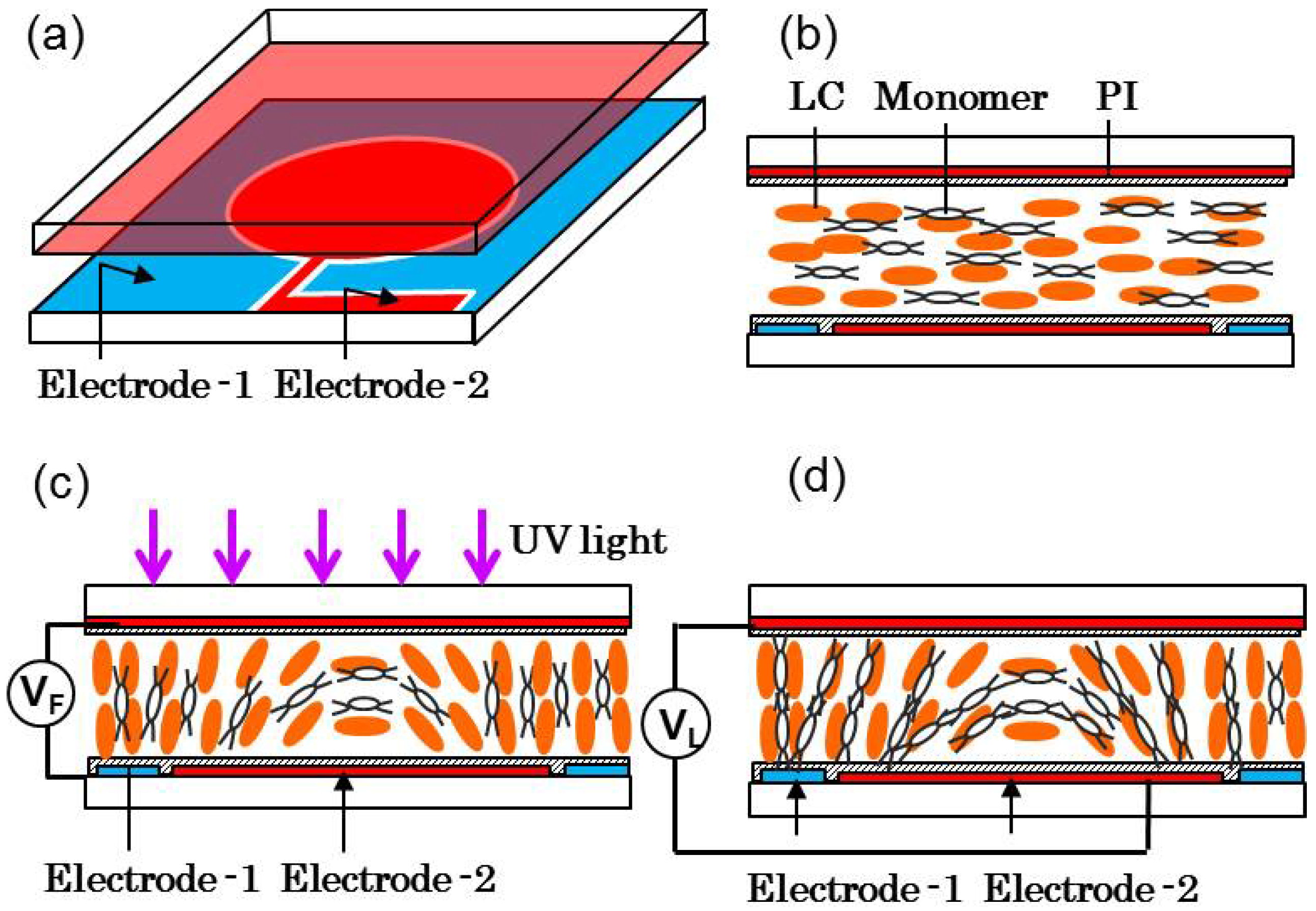
To utilize the maximum intrinsic birefringence of the LC material and present the shortest possible focal length, in 2013, Ren et al. demonstrated a PNLC microlens array using a ring-array-patterned electrode in a homogeneous cell [63]. Figure 4 shows the cell structure; the top substrate has a planar ITO electrode, while the bottom substrate has two patterned ITO electrodes (electrode-1 and electrode-2) for generating fringing field (VF) and uniform longitudinal field (VL) individually. The inner and outer radii of the ring are 50 μm and 70 μm, respectively. These two substrates are antiparallel rubbed and the cell gap is ~15 μm (Figure 4b). The LC/monomer layer consists of 90 wt % Merck BL-009 (no = 1.529, Δn = 0.281) and ~10 wt % RM257 (containing a small amount of photoinitiators). RM257 has a rod-like structure and can be easily aligned with LCs. The desired gradient refractive index profile in the LC/monomer layer is introduced by the fringing field (VF), and later stabilized by UV exposure to form polymer networks (Figure 4c). For the microlens with a 50 μm aperture, the shortest focal length is ~378 μm at VF = 6 Vrms and λ ~550 nm. Then, the LC/monomer mixture was photo-polymerized at VF = 6 Vrms, under UV exposure (λ ~365 nm, ~10 mW·cm−2) for 20 min. Once the PNLC is formed, it is difficult to be actuated by the fringing field. Instead, a uniform longitudinal electric field is adopted by applying a voltage (VL) between the top electrode and bottom electrode-2, which in turn changes the focal length (Figure 4d). As VL increases, the focal length increases gradually. When VL > 115 Vrms, the focal length is too long to be estimated. The response time from focusing to non-focusing and from non-focusing to focusing was measured to be ~3.6 ms and ~0.9 ms, respectively, under VL = 100 Vrms. As no photomask is employed during the UV polymerization process, the formed PNLC has a uniform morphology. Such a PNLC microlens array offers several attractive features, such as fast response time, good stability, and weak light scattering in the visible spectral range.
Figure 4.
PNLC microlens structure and fabrication procedures: (a) microlens structure; (b) LC/monomer mixture present a homogeneous alignment; (c) central-symmetric gradient refractive index distribution is introduced by inhomogeneous fringe field along with UV exposure and (d) the formed PNLC microlens after removing the voltage is actuated by a uniform longitudinal electric field.

2.3.3. Reconfigurable Fabrication of PNLC Lens/Microlens
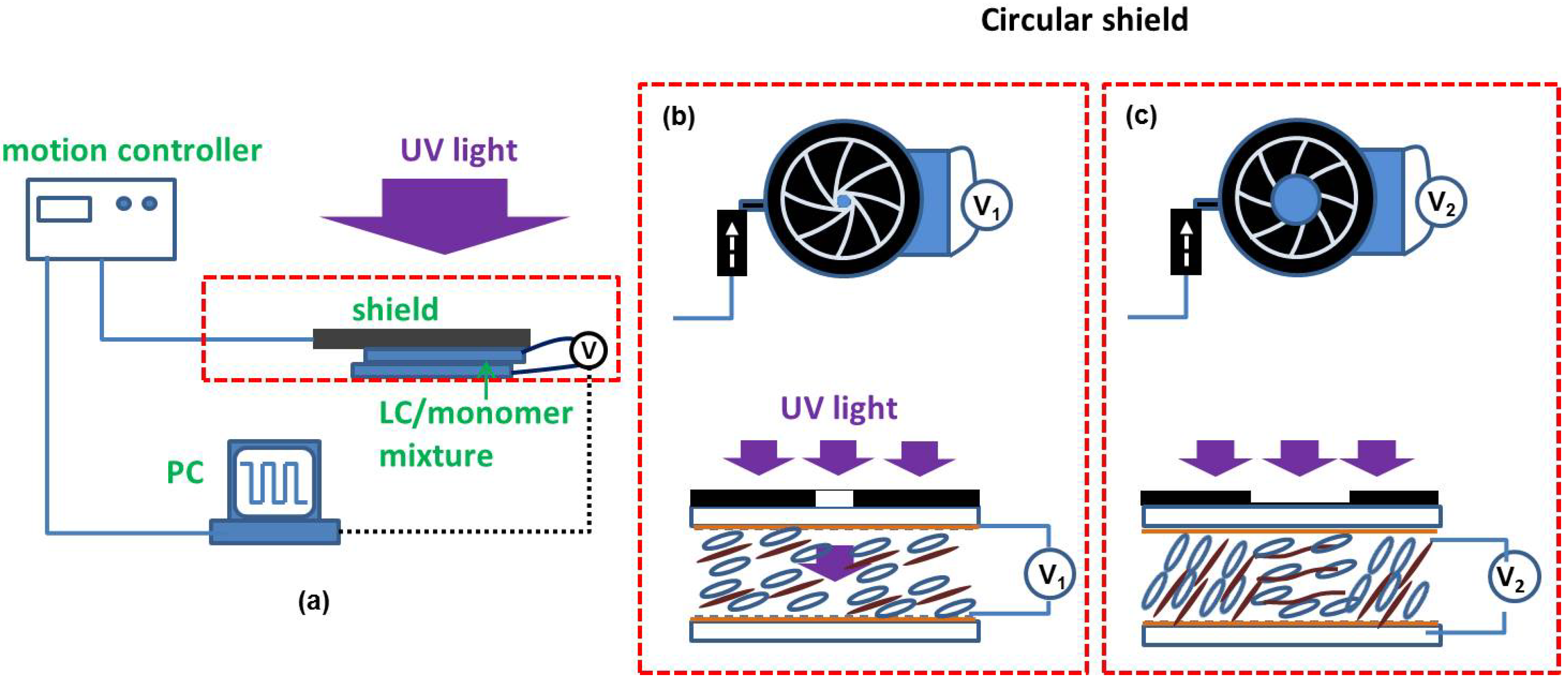
To fabricate the PSLC/PNLC microlens shown in Figure 3, Figure 4, a pre-patterned template, such as patterned photomask or electrode, is commonly used. The current fabrication techniques heavily involve photolithography procedure, which is expensive, time consuming and environmentally unfriendly (i.e., photoresistors and developers are toxic). In 2013, Sun et al. demonstrated a one-step printing technique to fabricate submillisecond-response and scattering-free PNLC lens [21]. Figure 5a depicts the experimental setup. A photomask, either an iris diaphragm (for circular lens) or a rectangular mask (for prism, cylindrical lens, or grating), is placed right above the LC cell and connected to a motion controller. The duration and amplitude of the applied voltages is controlled by LabVIEW. A UV lamp is used for stabilizing the polymer network. The essential part of this method is to control the LC tilt angle (through controlling voltage applied to the mixture) along with the exposure area (through controlling a movable shield), while a desired tilt angle at a specific position is fixed by UV exposure [64]. By repeating the same process at different positions and different voltages, various tilt angle distribution of the LC molecules can be obtained. Figure 5b,c show the fabrication procedures of a lens using an iris diaphragm. Here, the LC/monomer layer consists of 90 wt % HTG135200 (γ1/K11 ~119.6 ms·µm−2 at 22 °C) and 10 wt % RM257. By specifically selecting such a high viscosity LC host and performing UV curing at a low temperature (11 °C) [65], the light scattering in the visible region is negligible at 633 nm (and ~3% at 480 nm). For the PNLC lens with a 2.6 mm aperture and 15 µm cell gaps, its focal length can be tuned from 15 cm to 32 cm when the voltage increases from 0 to 100 Vrms. In comparison with conventional microfabrication techniques for adaptive LC photonic devices, this approach shows advantages in: (1) short fabrication time; (2) flexibility for designing and fabricating the desired refractive index profile of an LC device; (3) low cost and environmentally friendly; (4) large panel capability and (5) submillisecond device response time. This printing technique enables rapid design iterations for display and photonic devices.
Figure 5.
(a) Schematic drawing of the fabrication setup; (b) dynamic control of the iris diaphragm and exposure for generating spatial gradient refractive index at V1 and (c) at V2.
Figure 5.
(a) Schematic drawing of the fabrication setup; (b) dynamic control of the iris diaphragm and exposure for generating spatial gradient refractive index at V1 and (c) at V2.

2.3.4. Polymeric Lenticular Microlens Array for 2D/3D Switchable Displays
Electrically switchable two-dimensional (2D) and three-dimensional (3D) displays have attracted great attention lately and various approaches have been proposed [66,67,68,69,70,71,72]. Among them, liquid crystal display (LCD) integrated with a lenticular microlens array provides an autostereoscopic multi-view 3D display with high brightness [68,69,70,71]. In the 2D mode, each LC microlens has no focusing effect and the microlens array functions as an optical flat. In the 3D mode, each LC microlens exhibits a focusing effect. By turning on and off the microlens focusing effect, the display can be electrically switched between 2D and 3D modes. Therefore, LC lenticular microlens array has become a key component in switchable 2D/3D displays.
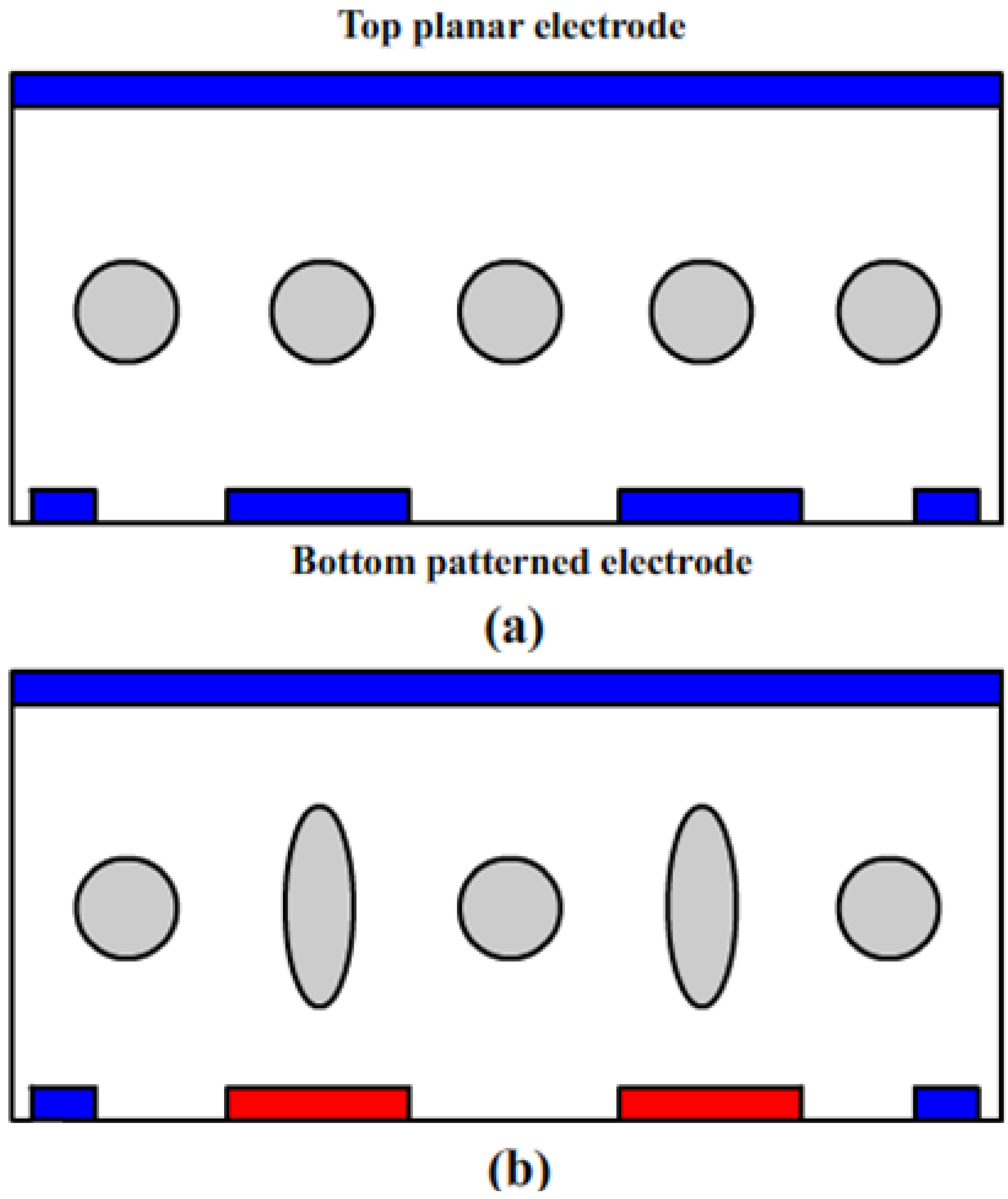
The abovementioned PDLC/PSLC/PNLC microlenses could provide a reasonable fast response time, however, the operating voltage is relatively high. To overcome these issues, Flack et al. proposed to indirectly actuate the LC lenticular microlens array through a twisted-nematic (TN) LC cell (also called a polarization converter) [1] to achieve 2D/3D switchable displays [73], as shown in Figure 6. Each LC microlens in the array covers two pixels: left and right. An isotropic polymer with a concave shape is used as the base for the LC microlens array. Let us assume the refractive index (np) of the isotropic polymer matches the ordinary refractive index (no) of the LC material. The LC in the lens cell presents homogeneous alignment. The optical axis of the polarizer is parallel to the rubbing direction of the bottom TN cell. In the voltage-off state, the polarization direction of the incident beam is rotated by 90° after passing through the TN cell, becoming orthogonal to the LC directors in the microlens. As a result, this beam will not be focused because np ~ no. The images from the left pixel and the right pixel can be seen by two eyes at the same time, and the display remains the original 2D display (Figure 6a). When a high voltage is applied to the TN cell, the LC directors are reoriented along the electric field direction and the polarization rotation effect vanishes. The outgoing beam from the TN cell behaves like an extraordinary ray to the microlens array. Because of ne > np and the convex shape of the LC microlens, the focusing effect occurs. For each microlens, the image coming from the right pixel can only be seen by the left eye, while that from the left pixel can only be detected by the right eye (Figure 6b). By combining these two images, our eyes will see 3D images out of the 2D panel.
Figure 6.
Operation principle of a switchable 2D/3D display with a TN broadband polarization rotator (middle) and a polymeric microlens array (top): (a) voltage-off and (b) voltage-on.
Figure 6.
Operation principle of a switchable 2D/3D display with a TN broadband polarization rotator (middle) and a polymeric microlens array (top): (a) voltage-off and (b) voltage-on.

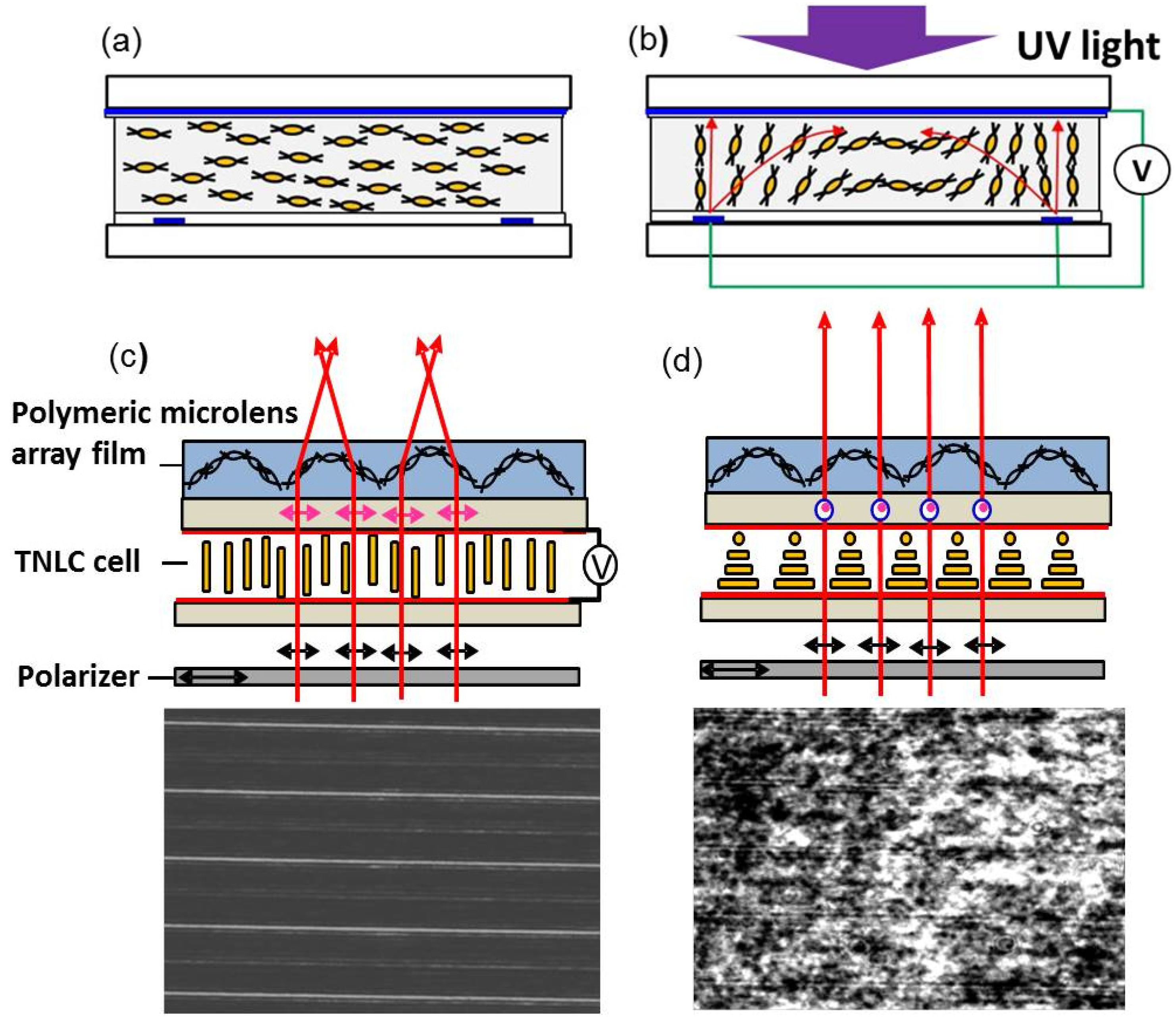
However, such a system requires a total of four glass substrates (Figure 5), which is too bulky and heavy. Ren et al. proposed to replace the LC microlens array with a lightweight polymeric microlens array film without compromising the performance [74]. This film was made of a mixture of rod-like diacrylate monomer (~80 wt % RM 257) and positive dielectric anisotropy nematic LC (~20 wt % Merck BL038). RM257 has a rod-like structure with reactive double bonds at both sides. Its nematic phase is from 70 °C to 130 °C. Compared to RM257 itself, the mixture exhibits two desired features: (1) positive Δε and (2) increased Δn. The mixture was filled into an antiparallel-rubbed cell at 75 °C (Figure 7a), and gradient refractive index profile in one microlens was induced by the fringing fields generated from a planar top electrode and striped bottom electrodes (Figure 7b). After UV stabilization, the polymerized film can be easily peeled from the substrate. Due to the crossed linking of the monomers, the nano-sized LC domains are tightly sealed in the film bulk and the film is optically anisotropic. Integrating with a 90° TN cell, the polymeric film exhibits focusing effect only to the extraordinary ray top sub-figure in (Figure 7c), and five focusing lines could be observed by the CCD camera, bottom sub-figure in Figure 7c. Turning off the TN cell, the polymeric film presents uniform refractive index to the ordinary ray, top sub-figure in Figure 7d, and no residual focusing effect is observed on the CCD camera, bottom sub-figure in Figure 7d. Under a 10 V pulse, the time from non-focusing (focusing) to focusing (non-focusing) was measured to be ~12 (~40) ms. In comparison to previous switchable LC lenses, Ren’s integrated TN/polymeric microlens film exhibits several unique features: (1) compact size; (2) temperature insensitivity; (3) large size capability; (4) switching with a low operating voltage (~5 V) and fast response time (<10 ms). The response time can be further reduced by using a low viscosity LC mixture in the TN cell. Since the film is first formed in a glass cell, and then peeled off from the substrate after opening the cell, this may cause defects or damages in the film. Meanwhile, the fabrication procedures are somewhat sophisticated.
Figure 7.
Operation principle of a switchable 2D/3D display with a TN broadband polarization rotator (middle) and a polymeric microlens array (top): (a) voltage-off, (b) voltage-on, (c) focusing state and (d) non-focusing state.
Figure 7.
Operation principle of a switchable 2D/3D display with a TN broadband polarization rotator (middle) and a polymeric microlens array (top): (a) voltage-off, (b) voltage-on, (c) focusing state and (d) non-focusing state.

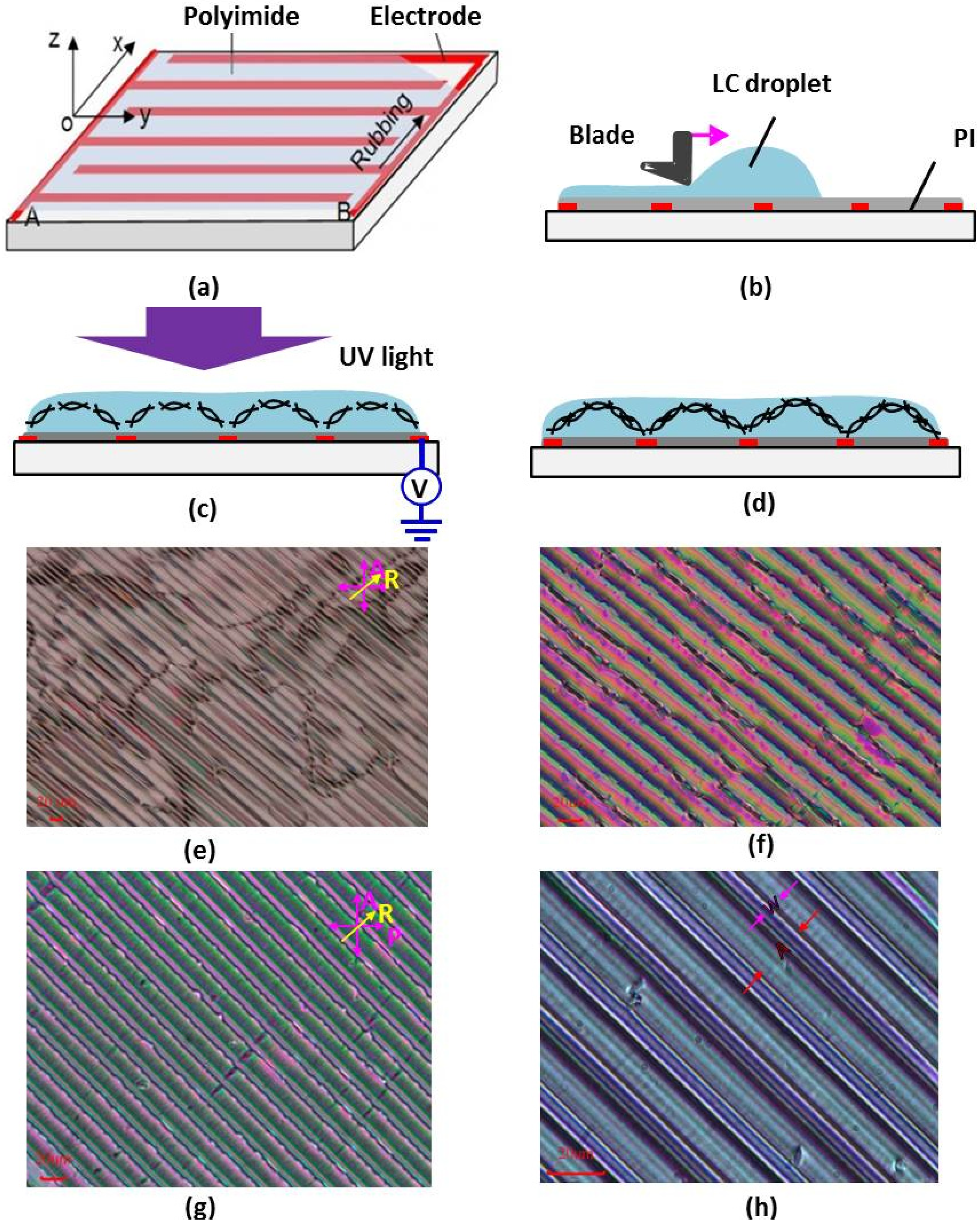
Ren et al. further simplified the fabrication procedures through directly forming the polymeric microlens array film on a single substrate with interdigitated ITO electrodes (Figure 8a) [75]. The coated PI layer was buffed along the x-direction, perpendicular to the electrode stripes. A droplet of LC/monomer mixture (~80 wt % RM 257 and ~20 wt % Merck BL009) was spread to be a thin film by a blade (Figure 8b). When the voltage is on, the LC molecules experience a dielectric force at the LC-air interface due to the fringing field, which is expressed as [76]:
![Micromachines 05 00300 i007]() where ε0 represents the permittivity of free space, V is volume of the droplet, εLC and εair (~1) are the dielectric constants of LC and air, respectively, and E is the electric field intensity. Since εLC is larger than εair, the dielectric force will pull the LC molecules to the region with higher electric field intensity. If the film is relatively thin, i.e., within the region where the gradient of the electric field intensity is still strong enough to generate a dielectric force comparable with the interfacial tension, it can be effectively flattened by the dielectric force. As a comparison, the LC molecules inside the film do not experience any dielectric force because of the same medium; instead, they are reoriented by the electric field, if they are located within the penetration depth of the electric field (Figure 6c). The gradient orientations of LC molecules in each period lead to a periodic gradient refractive index (GRIN) distribution in the film. As a result, the film exhibits a lens characteristic, which is later stabilized thorough UV polymerization (Figure 8d). It is found that the GRIN distribution within the film is mainly dependent on the applied voltage during UV exposure. If the generated fringing field is too weak to reorient the monomers/LCs, disclination lines and non-uniform GRIN distribution within each stripe appear (Figure 8e,f). When the voltage is sufficiently high, the generated fringing field is able to reorient the monomers/LCs and the stripes present a uniform color change (Figure 8g). Figure 8h is a magnified image showing several stripes. In one period, w is the width of the ITO stripe (8 μm) and A is the diameter of the lens aperture (20 μm). The uniform periodic color stripes imply that the surface of the polymeric film is very flat and each polymeric stripe has a GRIN distribution within it. Therefore, the film functions as a lenticular microlens array. When it is integrated with a 90° TN cell in a lens system, its focal length can be switched by actuating the TN cell.
where ε0 represents the permittivity of free space, V is volume of the droplet, εLC and εair (~1) are the dielectric constants of LC and air, respectively, and E is the electric field intensity. Since εLC is larger than εair, the dielectric force will pull the LC molecules to the region with higher electric field intensity. If the film is relatively thin, i.e., within the region where the gradient of the electric field intensity is still strong enough to generate a dielectric force comparable with the interfacial tension, it can be effectively flattened by the dielectric force. As a comparison, the LC molecules inside the film do not experience any dielectric force because of the same medium; instead, they are reoriented by the electric field, if they are located within the penetration depth of the electric field (Figure 6c). The gradient orientations of LC molecules in each period lead to a periodic gradient refractive index (GRIN) distribution in the film. As a result, the film exhibits a lens characteristic, which is later stabilized thorough UV polymerization (Figure 8d). It is found that the GRIN distribution within the film is mainly dependent on the applied voltage during UV exposure. If the generated fringing field is too weak to reorient the monomers/LCs, disclination lines and non-uniform GRIN distribution within each stripe appear (Figure 8e,f). When the voltage is sufficiently high, the generated fringing field is able to reorient the monomers/LCs and the stripes present a uniform color change (Figure 8g). Figure 8h is a magnified image showing several stripes. In one period, w is the width of the ITO stripe (8 μm) and A is the diameter of the lens aperture (20 μm). The uniform periodic color stripes imply that the surface of the polymeric film is very flat and each polymeric stripe has a GRIN distribution within it. Therefore, the film functions as a lenticular microlens array. When it is integrated with a 90° TN cell in a lens system, its focal length can be switched by actuating the TN cell.

Figure 8.
(a) A glass substrate with interdigitated ITO electrodes; (b) the droplet is spread to form a thin film with a blade; (c) voltage is applied to the electrodes and fringing field induced molecule reorientation is polymerized through UV exposure; (d) GRIN distribution remains after removing the voltage; (e) film textures observed on the IPS-8/12 substrate at V = 50 Vrm; (f) V = 65 Vrms to the fluidic film; (g) solidified after applying 80 Vrms and (h) magnified image of (f).

3. Polymer-Stabilized Blue Phase LC Microlens
3.1. Operation Principles
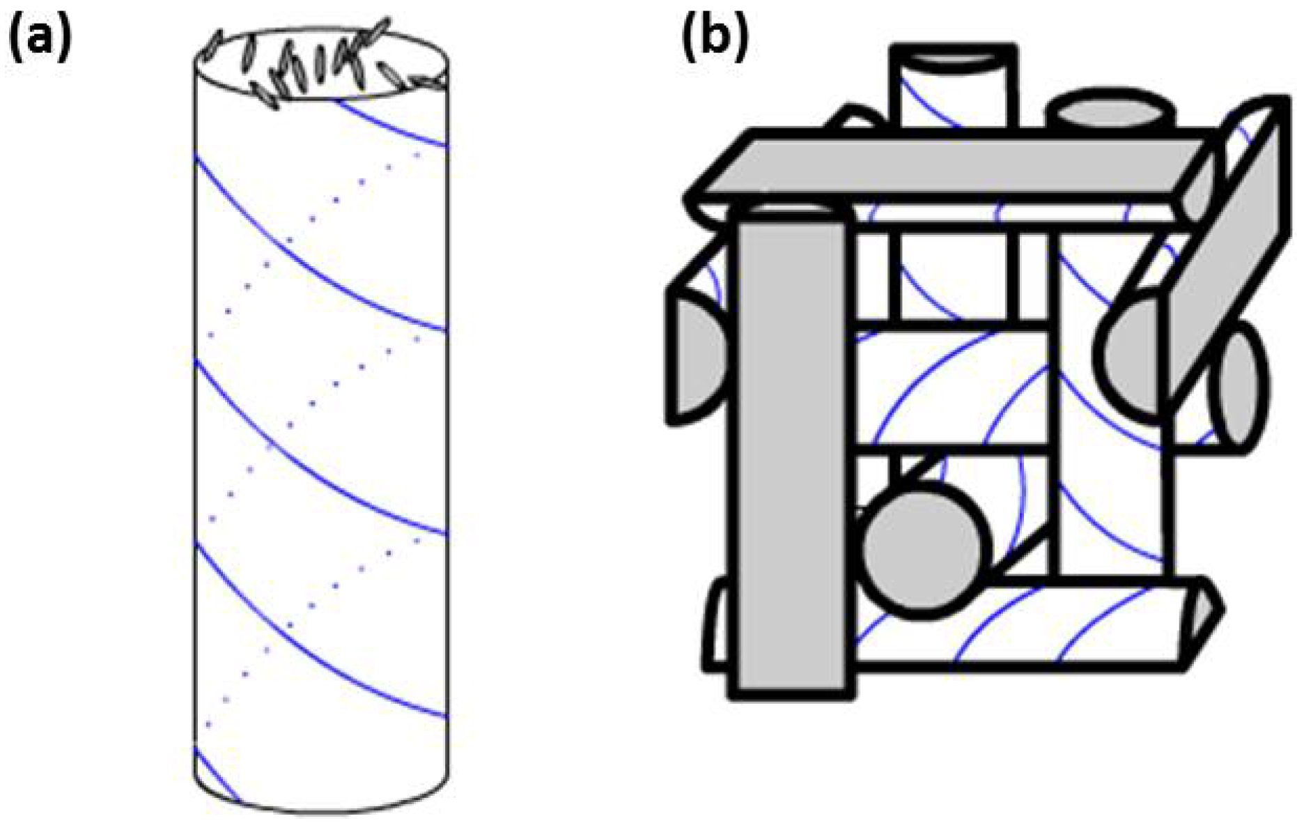
Polymer-stabilized blue phase liquid crystal (PS-BPLC) microlenses [28,29,30,31,32,33,34] have been developed with several attractive features: (1) submillisecond response time, (2) alignment-free, and (3) polarization insensitive. Blue phase [47,48,49,50] exists over a narrow temperature range (1–2 °C) between chiral nematic and isotropic phases. It is a self-assembled structure consisting of double-twist cylinders arranged in cubic lattice, as show in Figure 9. The pitch length of double twist structure measures several hundreds of nanometers. Due to the short coherent length, BPLC exhibits submillisecond response time [77]. Due to the symmetric three-dimensional cubic structure, it appears optically isotropic. For years, blue phase has been found scientifically interesting but has limited applications mainly due to its narrow temperature range. In 2002, Kikuchi et al. used polymer to successfully stabilize the double-twist structure and extended the temperature range of blue phase to more than 60 K (including room temperature) [48], which ushered a new era for blue phase.
Figure 9.
(a) Double twist cylinder structure and (b) cubic lattice of a blue phase.

When no voltage is applied, BPLC appears optically isotropic with refractive indices being the same in all directions ni. As an electric field is applied, birefringence is induced along the direction of electric field. The induced birefringence Δnind can be described by the Kerr effect in the low field region:
where λ is the wavelength and K is the Kerr constant. As the electric field increases, the induced birefringence gradually saturates and can be described by the extended Kerr model [78]:
![Micromachines 05 00300 i008]() where Δnsat stands for saturated induced birefringence, and Es represents the saturation field. Along the direction of the electric field, the refractive index is ne(E) = ni + 2Δn(E)/3, and in the orthogonal directions, the refractive indices are no(E) = ni − Δn(E)/3.
where Δnsat stands for saturated induced birefringence, and Es represents the saturation field. Along the direction of the electric field, the refractive index is ne(E) = ni + 2Δn(E)/3, and in the orthogonal directions, the refractive indices are no(E) = ni − Δn(E)/3.
Δnind = λKE2

3.2. PS-BPLC Microlens with Planar Electrode
The first PS-BPLC microlens was demonstrated by Lin et al. in 2010 [16]. The fast response time and polarization insensitivity were experimentally verified. The structure is shown in Figure 10a. The PS-BPLC is confined between two glass substrates with a cell gap of 20 μm. The top electrode has a hole pattern (diameter = 250 μm) in the center, while the bottom electrode is continuous. In the voltage-off state, the effective refractive index of BPLC is spherical. When voltage is applied between top and bottom electrodes, the effective optical index-ellipsoid of PS-BPLC turns out ellipsoidal due to induced birefringence. The index is more elongated ellipsoid at the edge than in the center due to the non-uniform electric field distribution (i.e., E3 > E2 > E1). Since the optic axes are in the direction of light propagation (z direction), both x and y polarizations experience ordinary refractive index no = ni − Δn(E)/3. At the edge of the aperture, the effective refractive index no is lower than that in the center, because of larger induced birefringence Δn(E). Such a spatial distribution of refractive indices forms a positive-lens-like phase profile. To characterize the microlens array, a collimated unpolarized green (λ = 532 nm) laser beam was used for illumination. Figure 10b shows the 2D images captured by a charge-coupled device (CCD) without voltage, and no obvious focusing is observed. Figure 10c shows the focusing (measured as 13 cm) at 100 Vrms. Moreover, this focusing effect is not affected by the incident polarization, therefore it is polarization insensitive. Such a BPLC microlens array is simple, fast responding, polarization insensitive and alignment free. However, such a simple structure has difficulty to generate ideal phase profile for achieving good image quality.
Figure 10.
(a) The cross section of a PS- microlens using a hole-patterned electrode; (b) measured CCD images of the 2D microlens array at 0 Vrms and (c) 100 Vrms.
Figure 10.
(a) The cross section of a PS- microlens using a hole-patterned electrode; (b) measured CCD images of the 2D microlens array at 0 Vrms and (c) 100 Vrms.

3.3. BPLC Microlens with Curved Electrode
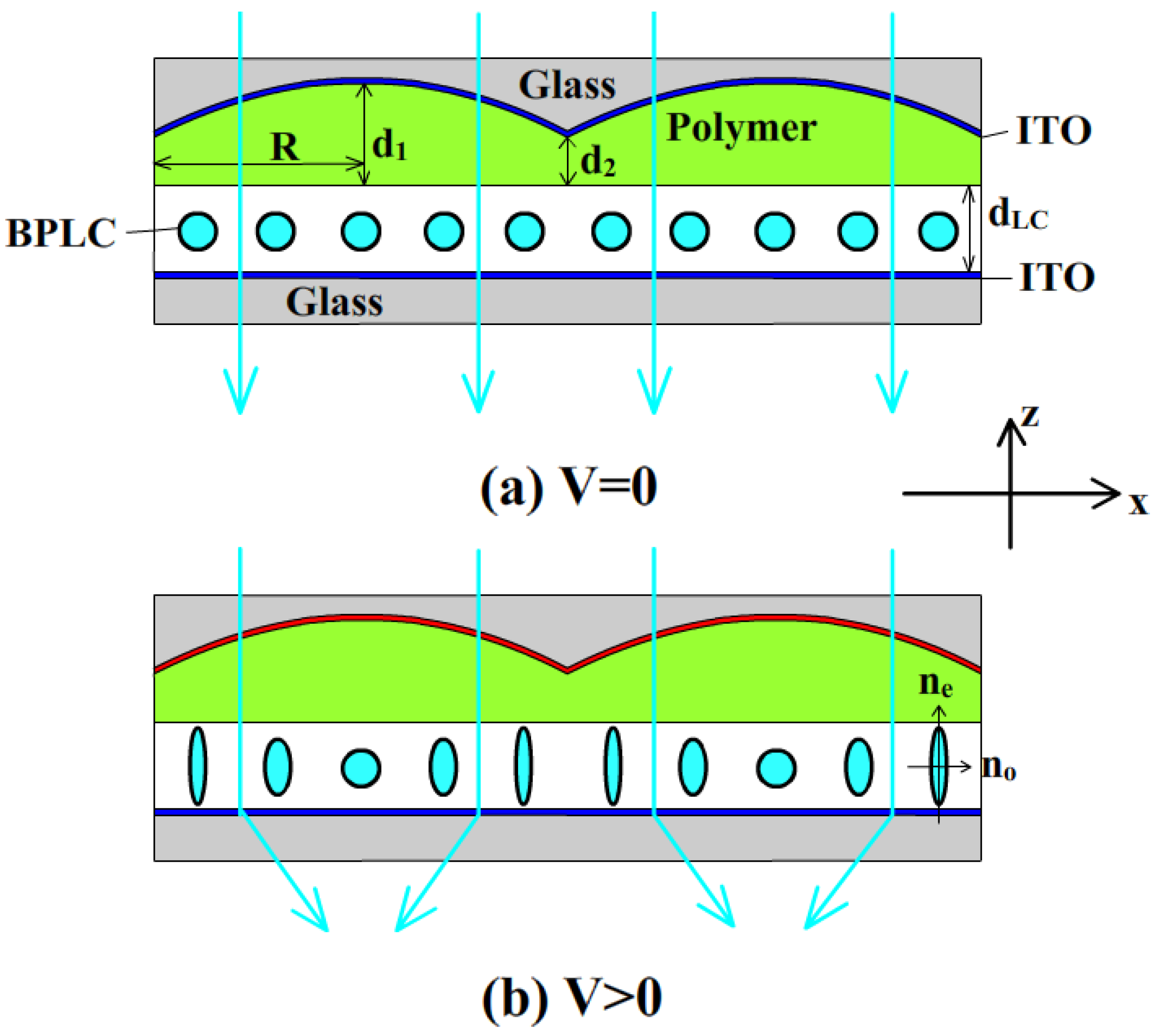
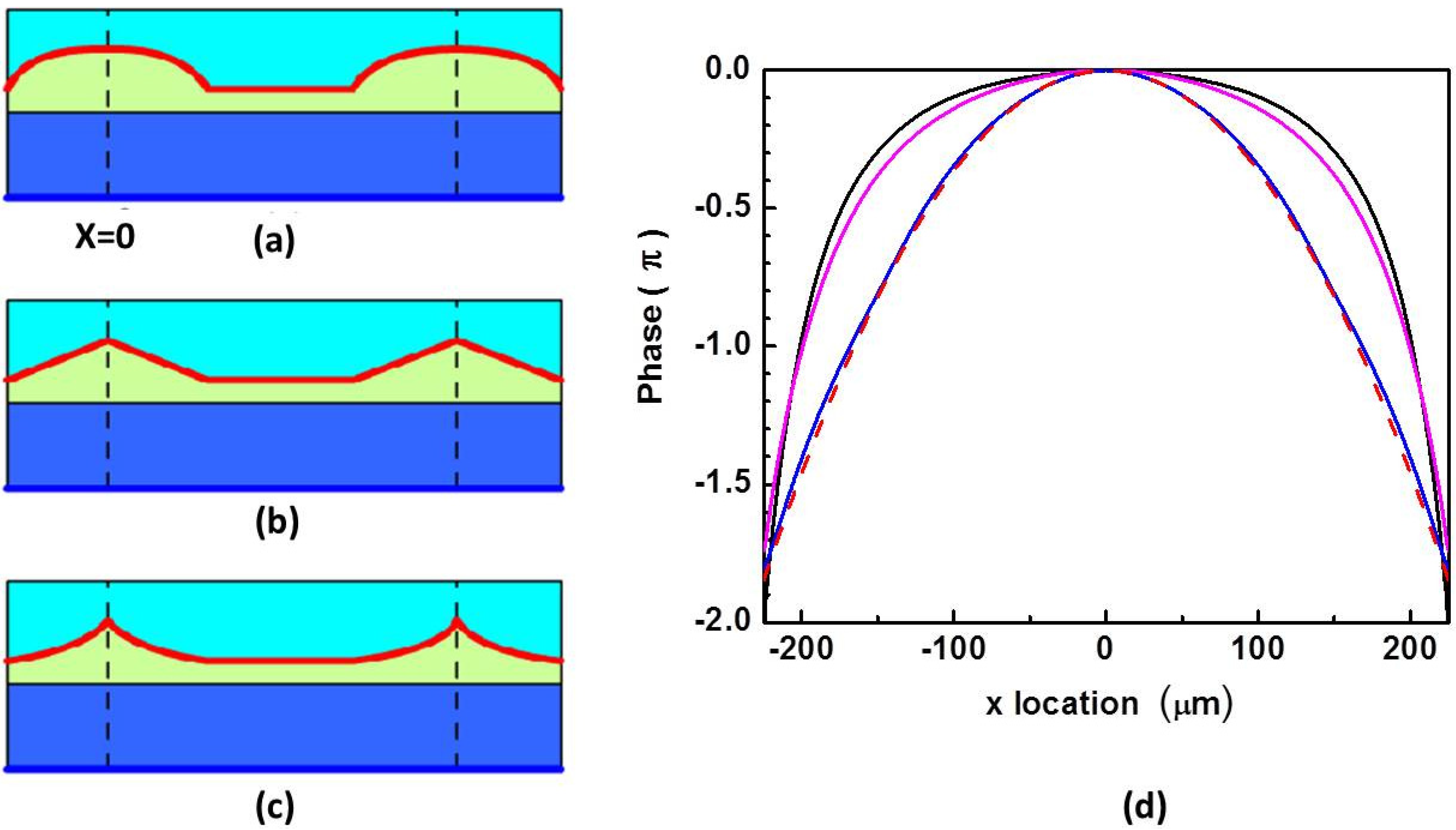
In 2011, Li et al. proposed another BPLC lens structure with curved electrode to improve the phase profile [33]. Figure 11 depicts the cross section (x-z plane) of the microlens array. The top glass substrate has a plano-concave microlens array profile. Its inner surface is coated with an ITO electrode, and then flattened by a polymer layer. The inner surface of the bottom substrate is coated with a planar ITO electrode A BPLC layer is sandwiched between these two substrates. The thickness of the polymer layer in the center of the lens d1 is much larger than that at the edge d2. In Figure 11a, At V = 0, the BPLC is optically isotropic and does not contribute to the optical power. So the propagation direction of the traversing light is not changed. In Figure 11b, as the applied voltage increases, vertical electric fields are generated across the aperture. Because of the curved shape of top ITO electrodes, the electric fields are much weaker in the center than at the edge, and consequently the induced birefringence is much smaller in the center. Therefore, the accumulated phase profile is like a positive lens, and the outgoing light is converged. Figure 12a–c depicts three microlens structures with different top electrode shapes. The black, pink and blue curves in Figure 12d are phase profiles of structure depicted in Figure 12a–c, respectively, and the red dashed line is an ideal parabolic shape. By controlling the shape of the curved ITO electrode, they can control the phase profile to approach parabolic shape so that the spherical aberration could be suppressed.
Figure 11.
The configuration and working principle of a PS-BPLC microlens using a curved ITO electrode, (a) voltage-off state and (b) voltage-on state.
Figure 11.
The configuration and working principle of a PS-BPLC microlens using a curved ITO electrode, (a) voltage-off state and (b) voltage-on state.

Figure 12.
(a), (b) and (c) Microlens structures with different top ITO electrode shapes, and (d) the simulated phase profiles: black line for structure (a), pink for structure (b), blue line for structure (c), and red dashed lines for an ideal parabolic shape.
Figure 12.
(a), (b) and (c) Microlens structures with different top ITO electrode shapes, and (d) the simulated phase profiles: black line for structure (a), pink for structure (b), blue line for structure (c), and red dashed lines for an ideal parabolic shape.

The focal length of the microlens could be calculated using the following formula:
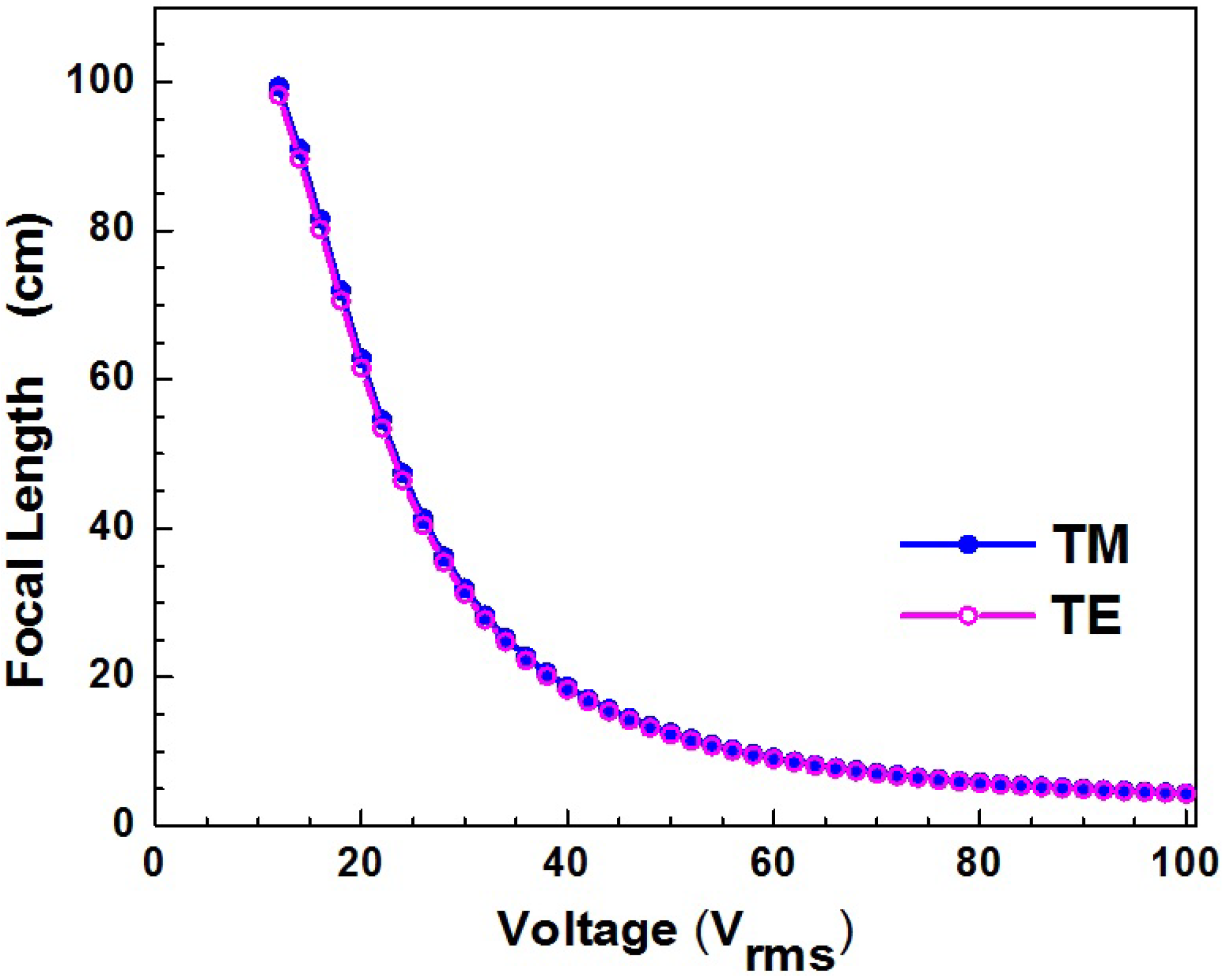
![Micromachines 05 00300 i009]() where Δn(E) is refractive index difference between the center and edge of the lens, dLC the cell gap, and R the semi-diameter of the lens. Figure 13 plots the focal lengths at different voltages for a specific structure (R = 225 mm, d1 = 76 mm, d2 = 2 mm, dLC = 17 μm), employing a blue phase material with a saturation birefringence Δn = 0.2 and saturation field Es = 5.6 V·μm−1. The blue curve and pink curve are for TM (x polarization) and TE (y polarization) waves, respectively. As shown in the figure, the two curves overlap very well and this lens is indeed polarization independent. With parabolic phase profile and polarization independency, it is an attractive design; however, the fabrication of such curved electrode is relatively difficult.
where Δn(E) is refractive index difference between the center and edge of the lens, dLC the cell gap, and R the semi-diameter of the lens. Figure 13 plots the focal lengths at different voltages for a specific structure (R = 225 mm, d1 = 76 mm, d2 = 2 mm, dLC = 17 μm), employing a blue phase material with a saturation birefringence Δn = 0.2 and saturation field Es = 5.6 V·μm−1. The blue curve and pink curve are for TM (x polarization) and TE (y polarization) waves, respectively. As shown in the figure, the two curves overlap very well and this lens is indeed polarization independent. With parabolic phase profile and polarization independency, it is an attractive design; however, the fabrication of such curved electrode is relatively difficult.

Figure 13.
Simulated focal lengths of a PS-BPLC microlens at different voltages.

3.4. PS-PBLC Microlens with Multi-Electrode
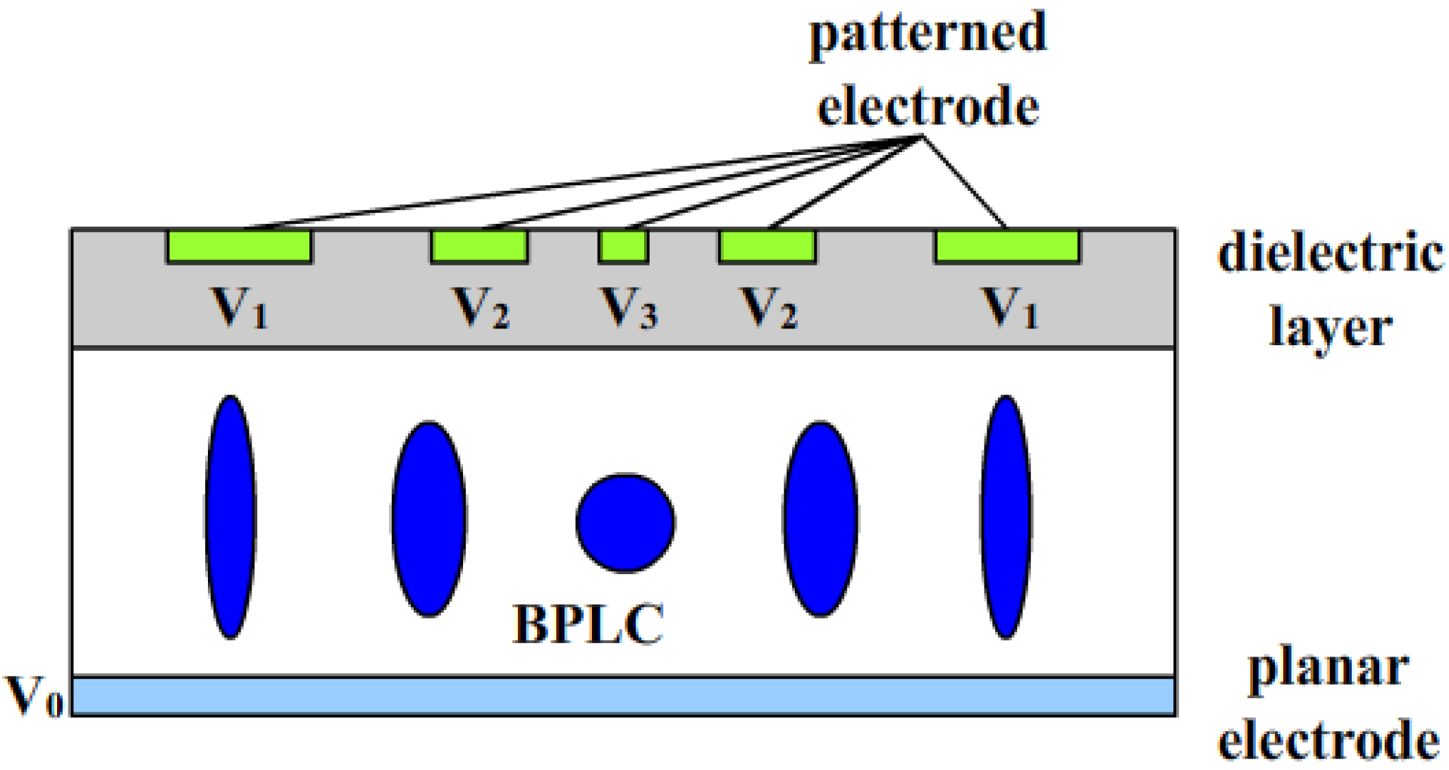
To simplify the structure, Lee et al. proposed a multi-electrode-structure PS-BPLC lens as shown in Figure 14 [32]. The bottom substrate has a planar electrode while the top glass substrate has multiple electrodes with different widths and different voltages. Below these electrodes, there is a high dielectric layer to smoothen the phase profile across the lens without shielding much of voltage. By individually controlling the voltage of each electrode, an ideally parabolic phase profile can be obtained. The planar structure of multi-electrode greatly simplifies the fabrication process. This lens remains polarization independent, fast response and has a parabolic phase shape. However, it requires multiple data addressing for multiple electrodes.
Figure 14.
The cross section of a PS-BPLC microlens with multiple electrodes.

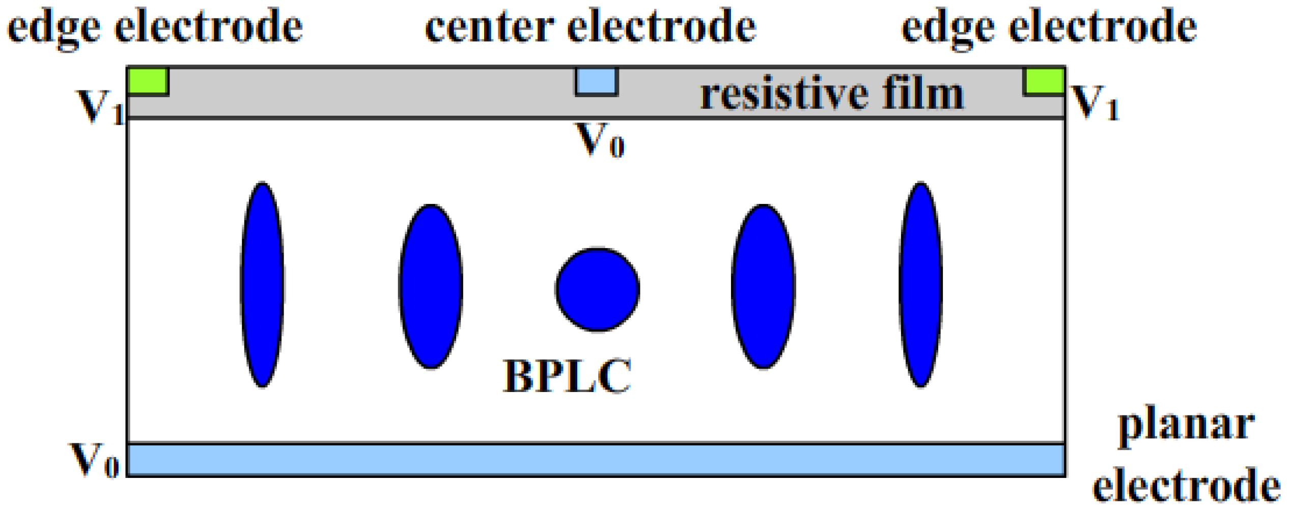
To further simplify the lens structure, a PS-BPLC cylindrical lens with a resistive film electrode was proposed [31]. As depicted in Figure 15, on the inner surface of top substrate, there is a center ITO electrode stripe at the center of the lens, and two ITO electrode stripes on the two edges, respectively. The aperture of the lens is further coated with a thin transparent high-resistive film. On the inner surface of the bottom substrate, a planar ITO electrode is coated. The resistive film has a linearly changing potential when different voltages are applied on two ends. As a result, the vertical electric field distribution also linearly varies from center to edge. In the low field region, where the Kerr effect dominates, the induced birefringence (Δn = λKE2) distribution is approximately parabolic, and so is the accumulated phase profile. Therefore, with only two electrodes, a natural parabolic phase profile is obtained. However, if the electric field further increases, saturation effect takes place, and the phase profile starts to deviate from parabolic shape gradually. Overall, this is simple design for achieving good lens performances: fast response, approximately parabolic phase profile, and polarization independency.
Figure 15.
The cross section of PS-BPLC microlens using a resistive film electrode.

3.5. Fresnel PS-PBLC Microlens
For a BPLC lens, usually the focal length is relatively long comparing to its nematic LC counterpart, and also the required voltage is high. To increase the dynamic range, Fresnel type BPLC lenses have been developed [28,29]. Figure 16 shows the configuration and working principle of the Fresnel BPLC lens [29]. An even-zone electrode is formed on one of the substrates, and a planar common electrode is formed on the other. At voltage-off state, BPLC is optically isotropic, and there is no lensing effect. When a voltage is applied between even-zone electrode and common electrode, the refractive index in the even zones is elongated in vertical direction, while the refractive index in the odd zones remains isotropic. As a result, phase difference between the odd and even zones is generated, and the BPLC Fresnel lens is switched on.
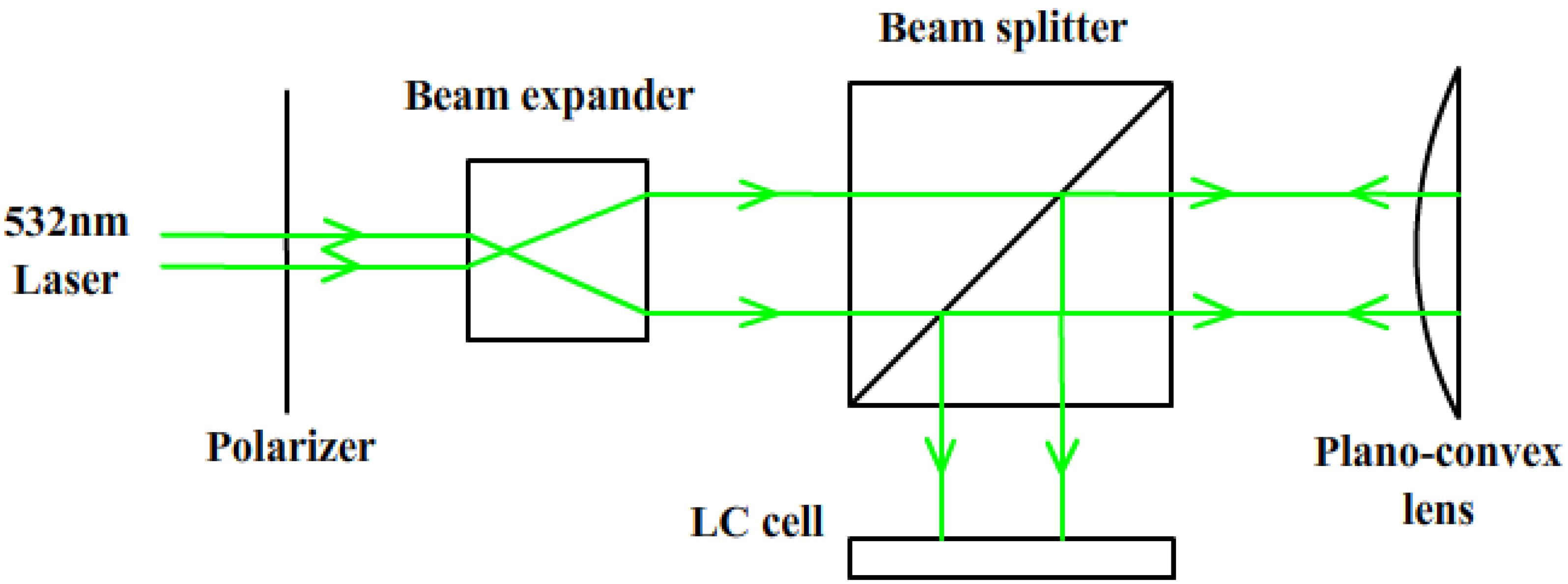
Recently, another Fresnel BPLC lens fabricated by holography was demonstrated [28]. Figure 17 depicts the schematic of experimental setup for fabricating such a lens. The interference between a planar and a spherical wavefronts generated by the plano-convex lens naturally produces a Fresnel pattern. A polymer/LC Fresnel lens was generated upon exposure, and then the LC was washed out and a BPLC mixture was refilled into the cell. When a voltage is applied between the planar electrodes, a focusing effect occurs.
Figure 16.
The device configuration and working principle of a Fresnel BPLC lens: (a) voltage-off state and (b) voltage-on state.
Figure 16.
The device configuration and working principle of a Fresnel BPLC lens: (a) voltage-off state and (b) voltage-on state.

Figure 17.
Schematic of experimental setup for making a Fresnel BPLC lens by holography.

4. Conclusions and Outlook
This paper gives an overview on the state-of-the-art, fast-response LC microlenses based on LC/polymer composites. As an important extension of pure LC systems, the LC/polymer composites offer more flexibility and much richer functionalities than the LC alone. Depending on the monomer concentration, three types of LC/polymer composites have been proposed for photonic applications: PDLC, PSLC, and PNLC. Benefiting from the anchoring effect of polymer networks, these microlenses exhibit much faster response times than pure nematic LC ones. Of particular interest, we reported on four types of microlenses: nano-PDLC microlens, PSLC microlens based on patterned photomask, PDLC microlens based on patterned electrode/reconfigurable fabrications, and polymeric lenticular microlens array for 2D/3D displays, and explained their device structures, operation mechanisms, and electro-optical performances.
To advance their emerging applications and transfer the laboratory prototypes to commercial products, several technical challenges still need to be addressed. An important limitation is the relatively high operating voltage. To suppress the light scattering in visible wavelength range, a small LC droplet/domain size is preferred, which usually requires a high voltage to actuate. For example, PNLC’s light scattering in the visible region is negligible at 633 nm (and ~3% at 480 nm) by selecting a high viscosity LC host and performing UV curing at a low temperature (11 °C), but the operating voltage is as high as 100 Vrms [65]. For nano-PDLC, the operating voltage is even higher, ~200 Vrms. Such a high operating voltage is not favorable for portable devices. Phase loss is a concern for PDLC/PSLC microlenses, since some LC molecules are strongly anchored by the polymer network and cannot contribute to the phase change. Therefore, the focal length tunability is rather limited. Another concern is the long-term stability of the polymer network. During the actuation, the reoriented LC domains may cause the polymer network to distort, and these distorted polymer networks may not recover to their original states. As a result, hysteresis occurs. Moreover, the distorted polymer network may lead to light scattering, which in turn degrades the lens quality. To achieve a good optical performance, the phase profile of the microlens needs to be optimized. Some PNLC microlenses suffer from astigmatism [63]. It can be reduced by using a thinner LC layer [79] or minimized by selecting a specific lens shape factor [80]. However, this shape factor is significantly different from that for minimizing its spherical aberration and coma [80]. To balance all the possible aberration arising in an LC lens, a proper shape factor should be chosen.
In addition to nematic LC/polymer composites, PS-BPLC, based on the Kerr effect, is an emerging candidate for new photonic applications. Compared with PDLC/PSLC/PNLC, BPLC microlenses have submillisecond response time. Additionally, they do not require any alignment layer, which could greatly simplify the fabrication process and improve the performance of microlenses with curved electrodes [34]. The scattering of PS-BPLC is determined by its Bragg reflection wavelength. By shifting the Bragg reflection band to UV, the scattering loss of PS-BPLC in the visible/IR band is negligible [81]. However, several problems remain to be overcome for blue phases. Firstly, due to the existence of polymer network, it is more difficult for the LC molecules to reorient in accordance to the electric field. Thus, a relatively high voltage is needed to drive the BPLC devices [16,29]. Secondly, in most tunable LC lenses, it is the variation of refractive index, rather than induced birefringence of LCs, determines the dynamic range of the focal length. For BPLC lens, however, the variations of both ordinary and extraordinary refractive indices are smaller than the induced birefringence so the dynamic range of the BPLC adaptive lens is narrower than its nematic counterpart [77]. Thirdly, all polymer-stabilized LC materials may have the long-term stability issue, if the driving voltage is higher than the onset of the electrostriction effect. Under such a circumstance, after multiple driving loops the bonding between LC molecules and polymer network might be undermined, and the polymer network itself might also be damaged. Therefore, the electro-optic properties of the LC devices will vary slowly during its entire lifetime [82]. Due to the narrow temperature range of the blue phase before stabilization, the temperature of BPLC precursor inside the LC lens chamber has to be controlled precisely during the UV exposure process, which makes mass production a challenge and increases the fabrication cost [48]. In order to solve this problem, a better BPLC material that is more tolerant to temperature variation has to be developed.
In conclusion, several types of fast-response microlenses have been demonstrated by introducing polymer networks into the pure LC system. They are attractive for practical applications in terms of fast response time, variable/switchable optical power, rapid prototyping, easy integration, low power consumption, simple driving, good mechanical stability, as well as reasonable operating voltage. As the advance of new LC/polymer materials, novel device designs, and fabrication approaches, their optical performances, as well as the electro-optical properties are expected to be more competitive. In the future, dielectrophoretically tunable optofluidic devices are foreseen to be low-cost, yet high-quality alternatives to various conventional solid-state photonic devices, and play a key role in the optical systems for imaging, information processing, sensing, optical communication, lab-on-a-chip, and biomedical engineering.
Acknowledgments
The UCF group is indebted to the U.S. Air Force Office of Scientific Research (AFOSR) for financial support under Contract No. FA95550-09-1-0170. H. Ren is supported by the National Research Foundation of Korea under Grant 2014001345.
Author Contributions
All authors helped conceive the idea and prepared the manuscript.
Conflicts of Interest
The authors declare no conflict of interest.
References
- Schadt, M.; Helfrich, W. Voltage-dependent optical activity of a twisted nematic liquid crystal. Appl. Phys. Lett. 1971, 18, 127–128. [Google Scholar] [CrossRef]
- Ren, H.; Xu, S.; Wu, S.T. Voltage-expandable liquid crystal surface. Lab Chip. 2011, 11, 3426–3430. [Google Scholar] [CrossRef]
- Bricot, C.; Hareng, M.; Spitz, E. Optical Projection Device and an Optical Reader Incorporating This Device. U.S. Patent 4,037,929, 29 January 1980. [Google Scholar]
- Li, L.; Bryant, D.; Heugten Van, T.; Bos, P.J. Near-diffraction-limited and low-haze electro-optical tunable liquid crystal lens with floating electrodes. Opt. Express 2013, 21, 8371–8381. [Google Scholar]
- Lin, H.C.; Collings, N.; Chen, M.S.; Lin, Y.H. A holographic projection system with an electrically tuning and continuously adjustable optical zoom. Opt. Express 2012, 20, 27222–27229. [Google Scholar] [CrossRef]
- Lin, Y.H.; Chen, M.S.; Lin, H.C. An electrically tunable optical zoom system using two composite liquid crystal lenses with a large zoom ratio. Opt. Express 2011, 19, 4714–4721. [Google Scholar] [CrossRef]
- Lin, Y.H.; Chen, H.S. Electrically tunable-focusing and polarizer-free liquid crystal lenses for ophthalmic applications. Opt. Express 2013, 21, 9428–9436. [Google Scholar] [CrossRef]
- Lin, H.C.; Lin, Y.H. A fast response and large electrically tunable-focusing imaging system based on switching of two modes of a liquid crystal lens. Appl. Phys. Lett. 2010, 97, 063505. [Google Scholar] [CrossRef]
- Nose, T.; Masuda, S.; Sato, S.; Li, J.; Chien, L.C.; Bos, P.J. Effects of low polymer content in a liquid-crystal microlens. Opt. Lett. 1997, 22, 351–353. [Google Scholar] [CrossRef]
- Naumov, A.F.; Loktev, M.Y.; Guralnik, I.R.; Vdovin, G. Liquid-crystal adaptive lenses with modal control. Opt. Lett. 1998, 23, 992–994. [Google Scholar]
- Ji, H.S.; Kim, J.H.; Kumar, S. Electrically controllable microlens array fabricated by anisotropic phase separation from liquid-crystal and polymer composite materials. Opt. Lett. 2003, 28, 1147–1149. [Google Scholar] [CrossRef]
- Choi, Y.; Park, J.H.; Kim, J.H.; Lee, S.D. Fabrication of a focal length variable microlens array based on a nematic liquid crystal. Opt. Mater. 2003, 21, 643–646. [Google Scholar] [CrossRef]
- Ren, H.; Wu, S.T. Tunable electronic lens using a gradient polymer network liquid crystal. Appl. Phys. Lett. 2003, 82, 22–24. [Google Scholar] [CrossRef]
- Presnyakov, V.V.; Galstian, T.V. Electrically tunable polymer stabilized liquid-crystal lens. J. Appl. Phys. 2005, 97, 103101–103106. [Google Scholar] [CrossRef]
- Kawamura, M.; Ye, M.; Sato, S. Optical particle manipulation using an LC device with eight-divided circularly hole-patterned electrodes. Opt. Express 2008, 16, 10059–10065. [Google Scholar] [CrossRef]
- Lin, Y.H.; Chen, H.S.; Lin, H.C.; Tsou, Y.S.; Hsu, H.K.; Li, W.Y. Polarizer-free and fast response microlens arrays using polymer-stabilized blue phase liquid crystals. Appl. Phys. Lett. 2010, 96, 113505. [Google Scholar] [CrossRef]
- Kao, Y.Y.; Chao, P.C.P.; Hsueh, C.W. A new low-voltage-driven GRIN liquid crystal lens with multiple ring electrodes in unequal widths. Opt. Express 2010, 18, 18506–18518. [Google Scholar]
- Tseng, M.C.; Fan, F.; Lee, C.Y.; Murauski, A.; Chigrinov, V.; Kwok, H.S. Tunable lens by spatially varying liquid crystal pretilt angles. J. Appl. Phys. 2011, 109, 083109. [Google Scholar] [CrossRef]
- Lu, L.; Sergan, V.; Van Heugten, T.; Duston, D.; Bhowmik, A.; Bos, P.J. Surface localized polymer aligned liquid crystal lens. Opt. Express 2013, 21, 7133–7138. [Google Scholar] [CrossRef]
- Masuda, S.; Takahashi, S.; Nose, T.; Sato, S.; Ito, H. Liquid-crystal microlens with a beam-steering function. Appl. Opt. 1997, 36, 4772–4778. [Google Scholar] [CrossRef]
- Sun, J.; Xu, S.; Ren, H.; Wu, S.T. Reconfigurable fabrication of scattering-free polymer network liquid crystal prism/grating/lens. Appl. Phys. Lett. 2013, 102, 161106. [Google Scholar] [CrossRef]
- Na, J.H.; Park, S.C.; Kim, S.U.; Choi, Y.; Lee, S.D. Physical mechanism for flat-to-lenticular lens conversion in homogeneous liquid crystal cell with periodically undulated electrode. Opt. Express 2012, 20, 864–869. [Google Scholar]
- Chen, C.W.; Huang, Y.P.; Chen, P.C. Dual direction overdriving method for accelerating 2D/3D switching time of liquid crystal lens on auto-stereoscopic display. J. Disp. Technol. 2012, 8, 559–561. [Google Scholar] [CrossRef]
- Fowler, C.W.; Pateras, E.S. Liquid crystal lens review. Ophthal. Physiol. Opt. 1990, 10, 186–194. [Google Scholar] [CrossRef]
- Lin, H.C.; Chen, M.S.; Lin, Y.H. A review of electrically tunable focusing liquid crystal lenses. Trans. Electr. Electron. Mater. 2011, 12, 234–240. [Google Scholar] [CrossRef]
- Ren, H.; Lin, Y.H.; Fan, Y.H.; Wu, S.T. Polarization-independent phase modulation using a polymer-dispersed liquid crystal. Appl. Phys. Lett. 2005, 86, 141110. [Google Scholar] [CrossRef]
- Lin, Y.H.; Ren, H.; Wu, Y.H.; Zhao, Y.; Fang, J.; Ge, Z.; Wu, S.T. Polarization-independent liquid crystal phase modulator using a thin polymer-separated double-layered structure. Opt. Express 2005, 13, 8746–8752. [Google Scholar]
- Tian, J.; Song, Y.; Zhu, J.L.; Ni, S.B.; Wang, Y.J.; Sun, X.Y.; Lu, J.G.; Yang, B.R.; Shieh, H.P.D. Blue phase LC/polymer fresnel lens fabricated by holographics. J. Disp. Technol. 2014, 10, 157–161. [Google Scholar] [CrossRef]
- Lin, C.H.; Wang, Y.Y.; Hsieh, C.W. Polarization-independent and high-diffraction-efficiency Fresnel lenses based on blue phase liquid crystals. Opt. Lett. 2011, 36, 502–504. [Google Scholar] [CrossRef]
- Liu, Y.; Li, Y.; Wu, S.T. Polarization-independent adaptive lens with two different blue-phase liquid-crystal layers. Appl. Opt. 2013, 52, 3216–3220. [Google Scholar] [CrossRef]
- Li, Y.; Liu, Y.; Li, Q.; Wu, S.T. Polarization independent blue-phase liquid crystal cylindrical lens with a resistive film. Appl. Opt. 2012, 51, 2568–2572. [Google Scholar] [CrossRef]
- Lee, C.T.; Li, Y.; Lin, H.Y.; Wu, S.T. Design of polarization-insensitive multi-electrode GRIN lens with a blue-phase liquid crystal. Opt. Express 2011, 19, 17402–17407. [Google Scholar]
- Li, Y.; Wu, S.T. Polarization independent adaptive microlens with a blue-phase liquid crystal. Opt. Express 2011, 19, 8045–8050. [Google Scholar] [CrossRef]
- Lin, S.H.; Huang, L.S.; Lin, C.H.; Kuo, C.T. Polarization-independent and fast tunable microlens array based on blue phase liquid crystals. Opt. Express 2014, 22, 925–930. [Google Scholar] [CrossRef]
- Wang, B.; Ye, M.; Sato, S. Liquid crystal lens with stacked structure of liquid-crystal layers. Opt. Commun. 2005, 250, 266–273. [Google Scholar] [CrossRef]
- Huang, Y.; Wen, C.H.; Wu, S.T. Polarization-independent and submillisecond response phase modulators using a 90° twisted dual-frequency liquid crystal. Appl. Phys. Lett. 2006, 89, 021103. [Google Scholar] [CrossRef]
- Ren, H.; Lin, Y.H.; Wu, S.T. Polarization-independent and fast-response phase modulators using double-layered liquid crystal gels. Appl. Phys. Lett. 2006, 88, 061123. [Google Scholar] [CrossRef]
- Fuh, A.Y.G.; Ko, S.W.; Huang, S.H.; Chen, Y.Y.; Lin, T.H. Polarization-independent liquid crystal lens based on axially symmetric photoalignment. Opt. Express 2011, 19, 2294–2300. [Google Scholar]
- Kao, Y.Y.; Chao, P.C.P. A new fual-grequency liquid crystal lens with ring-and-pie electrodes and a driving scheme to prevent disclination lines and improve recovery time. Sensors 2011, 11, 5402–5415. [Google Scholar] [CrossRef]
- Pishnyak, O.; Sato, S.; Lavrentovich, O.D. Electrically tunable lens based on a dual-frequency nematic liquid crystal. Appl. Opt. 2006, 45, 4576–4582. [Google Scholar] [CrossRef]
- Schadt, M. Dielectric heating and relaxations in nematic liquid crystals. Mol. Cryst. Liq. Cryst. 1981, 66, 319–336. [Google Scholar] [CrossRef]
- Kim, J.H.; Kumar, S. Fabrication of electrically controllable microlens array using liquid crystals. J. Lightwave Technol. 2005, 23, 628–632. [Google Scholar] [CrossRef]
- Kim, J.H.; Kumar, S. Fast switchable and bistable microlens array using ferroelectric liquid crystals. Jpn. J. Appl. Phys. 2004, 43, 7050. [Google Scholar] [CrossRef]
- Lee, Y.M.; Gwag, J.; Choi, Y.; Lee, K.H.; Yu, C.J.; Kim, J.H. Fast switching characteristics of a microlens array using the electroclinic effect of SmA* liquid crystals. Appl. Opt. 2009, 48, 3737–3741. [Google Scholar] [CrossRef]
- Rao, L.; Ge, Z.; Wu, S.T.; Lee, S.H. Low voltage blue-phase liquid crystal displays. Appl. Phys. Lett. 2009, 95, 231101. [Google Scholar] [CrossRef]
- Ge, Z.; Gauza, S.; Jiao, M.; Xianyu, H.; Wu, S.T. Electro-optics of polymer-stabilized blue phase liquid crystal displays. Appl. Phys. Lett. 2009, 94, 101104. [Google Scholar] [CrossRef]
- Haseba, Y.; Kikuchi, H.; Nagamura, T.; Kajiyama, T. Large electro-optic Kerr effect in nanostructured chiral liquid-crystal composites over a wide temperature range. Adv. Mater. 2005, 17, 2311–2315. [Google Scholar] [CrossRef]
- Kikuchi, H.; Yokota, M.; Hisakado, Y.; Yang, H.; Kajiyama, T. Polymer-stabilized liquid crystal blue phases. Nat. Mater. 2002, 1, 64–68. [Google Scholar] [CrossRef]
- Yan, J.; Rao, L.; Jiao, M.; Li, Y.; Cheng, H.C.; Wu, S.T. Polymer-stabilized optically isotropic liquid crystals for next-generation display and photonics applications. J. Mater. Chem. 2011, 21, 7870–7877. [Google Scholar] [CrossRef]
- Yan, J.; Wu, S.T. Polymer-stabilized blue phase liquid crystals: a tutorial. Opt. Mater. Express 2011, 1, 1527–1535. [Google Scholar] [CrossRef]
- Chen, Y.; Xianyu, H.; Sun, J.; Kula, P.; Dabrowski, R.; Tripathi, S.; Twieg, R.J.; Wu, S.T. Low absorption liquid crystals for mid-wave infrared applications. Opt. Expr. 2011, 19, 10843–10848. [Google Scholar]
- Khoo, I.C.; Wu, S.T. Optics and Nonlinear Optics of Liquid Crystals; World Scientific: Singapore, 1993. [Google Scholar]
- Ren, H.; Wu, S.T. Introduction to Adaptive Lenses; Wiley: Hoboken, New Jersey, NY, US, 2012. [Google Scholar]
- Ren, H.; Fan, Y.H.; Lin, Y.H.; Wu, S.T. Tunable-focus microlens arrays using nanosized polymer-dispersed liquid crystal droplets. Opt. Commun. 2005, 247, 101–106. [Google Scholar] [CrossRef]
- Presnyakov, V.; Asatryan, K.; Galstian, T.; Tork, A. Polymer-stabilized liquid crystal for tunable microlens applications. Opt. Express 2002, 10, 865–870. [Google Scholar] [CrossRef]
- Ren, H.; Fan, Y.H.; Gauza, S.; Wu, S.T. Tunable microlens arrays using polymer network liquid crystal. Opt. Commun. 2004, 230, 267–271. [Google Scholar] [CrossRef]
- Gauza, S.; Wang, H.; Wen, C.H.; Wu, S.T.; Seed, A.J.; Dabrowski, R. High birefringence isothiocyanato tolane liquid crystals. Jpn. J. Appl. Phys. 2003, 42, 3463–3466. [Google Scholar] [CrossRef]
- Gauza, S.; Wen, C.H.; Wu, S.T.; Janarthanan, N.; Hsu, C.S. Super high birefringence isothiocyanato biphenyl-bistolane liquid crystals. Jpn. J. Appl. Phys. 2004, 43, 7634–7638. [Google Scholar] [CrossRef]
- Doane, J.W.; Vaz, N.A.; Wu, B.G.; Žumer, S. Field controlled light scattering from nematic microdroplets. Appl. Phys. Lett. 1986, 48, 269–271. [Google Scholar] [CrossRef]
- Rajaram, C.V.; Hudson, S.D.; Chien, L.C. Morphology of polymer-stabilized liquid crystals. Chem. Mater. 1995, 7, 2300–2308. [Google Scholar] [CrossRef]
- Ren, H.; Fan, Y.H.; Wu, S.T. Polymer network liquid crystals for tunable microlens arrays. J. Phys. D Appl. Phys. 2004, 37, 400–403. [Google Scholar] [CrossRef]
- Xu, M.; Zhou, Z.; Ren, H.; Seung, H.; Wang, Q. A microlens array based on polymer network liquid crystal. J. Appl. Phys. 2013, 113, 053105. [Google Scholar] [CrossRef]
- Ren, H.; Xu, S.; Wu, S.T. Polymer-stabilized liquid crystal microlens array with large dynamic range and fast response time. Opt. Lett. 2013, 38, 3144–3147. [Google Scholar] [CrossRef]
- Ren, H.; Xu, S.; Wu, S.T. Gradient polymer network liquid crystal with a large refractive index change. Opt. Express 2012, 20, 26464–26472. [Google Scholar] [CrossRef]
- Sun, J.; Chen, Y.; Wu, S.T. Submillisecond-response and scattering-free infrared liquid crystal phase modulators. Opt. Express 2012, 20, 20124–20129. [Google Scholar] [CrossRef]
- Woodgate, G.J.; Harrold, J.; Jacobs, A.M.S.; Moseley, R.R.; Ezra, D. Flat-panel autostereoscopic displays: characterization and enhancement. In Proceedings of the SPIE 3957, Stereoscopic Displays and Virtual Reality Systems VII, San Jose, CA, USA, 22 January 2000; p. 153.
- Choi, H.; Park, J.H.; Kim, J.; Cho, S.W.; Lee, B. Wide-viewing-angle 3D/2D convertible display system using two display devices and a lens array. Opt. Express 2005, 13, 8424–8432. [Google Scholar] [CrossRef]
- Dekker, T.; de Zwart, S.T.; Willemsen, O.H.; Hiddink, M.G.H.; Ijzerman, W.L. 2D/3D switchable displays. In Proceedings of SPIE 6196, Photonics in Multimedia, 61960H, Strasbourg, France, 3 April 2006.
- Krijn, M.P.C.M.; de Zwart, S.T.; de Boer, D.K.G.; Willemsen, O.H.; Sluijter, M. 2D/3D displays based on switchable lenticulars. J. Soc. Inf. Disp. 2008, 16, 847–855. [Google Scholar] [CrossRef]
- Takagi, A.; Saishu, T.; Kashiwagi, M.; Taira, K.; Hirayama, Y. Autostereoscopic partial 2-D/3-D switchable display using liquid-crystal gradient index lens. SID Symp. Dig. 2010, 41, 436–439. [Google Scholar] [CrossRef]
- Chen, C.W.; Huang, Y.C.; Huang, Y.P.; Huang, J.F. Fast switching fresnel liquid crystal lens for autostereoscopic 2D/3D display. SID Symp. Dig. 2010, 41, 428–431. [Google Scholar] [CrossRef]
- Lai, Y.K.; Lai, Y.F.; Chen, Y.C. An effective hybrid depth-generation algorithm for 2D-to-3D conversion in 3D displays. J. Disp. Technol. 2013, 9, 154–161. [Google Scholar] [CrossRef]
- Flack, J.; Harrold, J.; Woodgate, G.J. A prototype 3D mobile phone equipped with a next-generation autostereoscopic display. In Proceedings of SPIE 6490, Stereoscopic Displays and Virtual Reality Systems XIV, San Jose, CA, USA, 28 January 2007.
- Ren, H.; Xu, S.; Liu, Y.; Wu, S.T. Switchable focus using a polymeric lenticular microlens array and a polarization rotator. Opt. Express 2013, 21, 7916–7925. [Google Scholar] [CrossRef]
- Ren, H.; Xu, S.; Liu, Y.; Wu, S.T. Optically anisotropic microlens array film directly formed on a single substrate. Opt. Express 2013, 21, 29304–29312. [Google Scholar]
- Jones, T.B. Electromechanics of Particles; Cambridge Universtiy Press: Cambridge, UK, 1995. [Google Scholar]
- Chen, K.M.; Gauza, S.; Xianyu, H.; Wu, S.T. Submillisecond gray-level response time of a polymer-stabilized blue-phase liquid crystal. J. Disp. Technol. 2010, 6, 49–51. [Google Scholar] [CrossRef]
- Yan, J.; Cheng, H.C.; Gauza, S.; Li, Y.; Jiao, M.; Rao, L.; Wu, S.T. Extended Kerr effect of polymer-stabilized blue-phase liquid crystals. Appl. Phys. Lett. 2010, 96, 071105. [Google Scholar] [CrossRef]
- Kikuta, H.; Iwata, K.; Shimomura, H. First-order aberration of a double-focus lens made of a uniaxial crystal. J. Opt. Soc. Am. A 1992, 9, 814–819. [Google Scholar] [CrossRef]
- Lesso, J.P.; Duncan, A.J.; Sibbett, W.; Padgett, M.J. Aberrations introduced by a lens made from a birefringent material. Appl. Opt. 2000, 39, 592–598. [Google Scholar]
- Kikuchi, H.; Higuchi, H.; Haseba, Y.; Iwata, T. Fast electro-Optical switching in polymer-stabilized liquid crystalline blue ohases for display application. SID Symp. Dig. 2007, 38, 1737–1740. [Google Scholar] [CrossRef]
- Lan, Y.F.; Tsai, C.Y.; Lu, J.K.; Sugiura, N. Mechanism of hysteresis in polymer-network stabilized blue phase liquid crystal. Polymer 2013, 54, 1876–1879. [Google Scholar] [CrossRef]
© 2014 by the authors; licensee MDPI, Basel, Switzerland. This article is an open access article distributed under the terms and conditions of the Creative Commons Attribution license (http://creativecommons.org/licenses/by/3.0/).
Share and Cite
MDPI and ACS Style
Xu, S.; Li, Y.; Liu, Y.; Sun, J.; Ren, H.; Wu, S.-T. Fast-Response Liquid Crystal Microlens. Micromachines 2014, 5, 300-324. https://doi.org/10.3390/mi5020300
AMA Style
Xu S, Li Y, Liu Y, Sun J, Ren H, Wu S-T. Fast-Response Liquid Crystal Microlens. Micromachines. 2014; 5(2):300-324. https://doi.org/10.3390/mi5020300
Chicago/Turabian StyleXu, Su, Yan Li, Yifan Liu, Jie Sun, Hongwen Ren, and Shin-Tson Wu. 2014. "Fast-Response Liquid Crystal Microlens" Micromachines 5, no. 2: 300-324. https://doi.org/10.3390/mi5020300