1. Introduction
Because of rapid advances in semiconductor manufacturing technology, the computing speed of electronic chips is increasing, their size is decreasing, and more transistors can be integrated in their design. Therefore, to dissipate the extremely high power density generated by current chips, effective thermal management is an urgent task that must be addressed for the further development of electronic devices. Heat pipes have been widely applied in the electronic cooling field because they are capable of passively transferring a large amount of heat with a small temperature difference.
A pulsating heat pipe (PHP) is typically a multiturn capillary tube containing a working fluid with a specific charge ratio that enables both the liquid and vapor phases to coexist in the tube. Because PHPs are wickless, they function in a considerably different manner compared with the manner in which traditional heat pipes function; furthermore, they are easily manufactured and possess fewer operating limitations [
1]. Because of the saturation pressure variation that occurs along the channels and the expansion and contraction of the vapor volume in the evaporator and condenser, respectively, oscillating and circulating motions of the working fluid within a PHP can be induced to enable the heat in both sensible and latent forms to be transported from the evaporator to the condenser [
2]. Maydanik
et al. [
3] and Yang
et al. [
4] have applied a pulsating heat pipe as a compact electronic cooler.
The various effects of influential parameters, including internal diameter, operating inclination angle, working fluid (e.g., water, methanol, ethanol, R-123, FC-72), and number of turns, on the thermal performance of closed-loop PHPs have been experimentally investigated in studies such as Charoensawan
et al. [
5], Zhang
et al. [
6], Thompson
et al. [
7], Youn and Kim [
8], and Chien
et al. [
9].
Another subject of interest is the phenomenon of vapor/liquid two-phase flow in a closed-loop PHP. Tong
et al. [
10] and Charoensawan
et al. [
11] observed that the working fluid exhibited large-amplitude oscillations during the start-up process. In addition, Xu
et al. [
12] observed that the bubble displacements and velocities displayed sine oscillation waves, but the local oscillation waves were superimposed, occurred forshort periods, and exhibited small oscillation amplitudes. Experimental investigations of the thermal performance of PHPs in which functional thermal fluids or nanofluid [
13,
14,
15,
16] are used as the working fluid were also conducted to explore the heat-transport capability of the PHP.
Recently, Qu
et al. [
17] fabricated a silicon-based micro pulsating heat pipe (μPHP) that exhibited trapezoidal microchannels that were 394 µm in hydraulic diameter. The evaporating, adiabatic, and condensing sections of the μPHP were primarily occupied by annular, slug, and slug-bubbly flows, respectively, at a steady state characterized by the sustained and self-exciting oscillations of the working fluid.
Although the inner diameter of a tube-type PHP can be small, its covering area can be several hundred square centimeters. Thus, the use of a flat PHP is likely to be more favorable because its configuration is convenient for miniaturization. With the aid of a micro-electromechanical fabrication technique, Youn and Kim [
8] fabricated and tested the thermal performance of a silicon-based pulsating heat spreader having uniform rectangular microchannels with a hydraulic diameter of 571 μm. In this study, Si-based μPHPs containing uniform and nonuniform channels were fabricated using a photolithography process and deep reactive-ion etching (DRIE). A dielectric liquid, HFE-7100, was used as the working fluid. The μPHPs were visually observed and the temperatures were measured. The purposes of this study were to develop Si-based μPHPs by using a nonuniform channel design to introduce an imbalanced capillary force, and relate the junction temperature response to the oscillating behavior of two-phase flow in μPHPs under various operating conditions.
2. Experimental Section
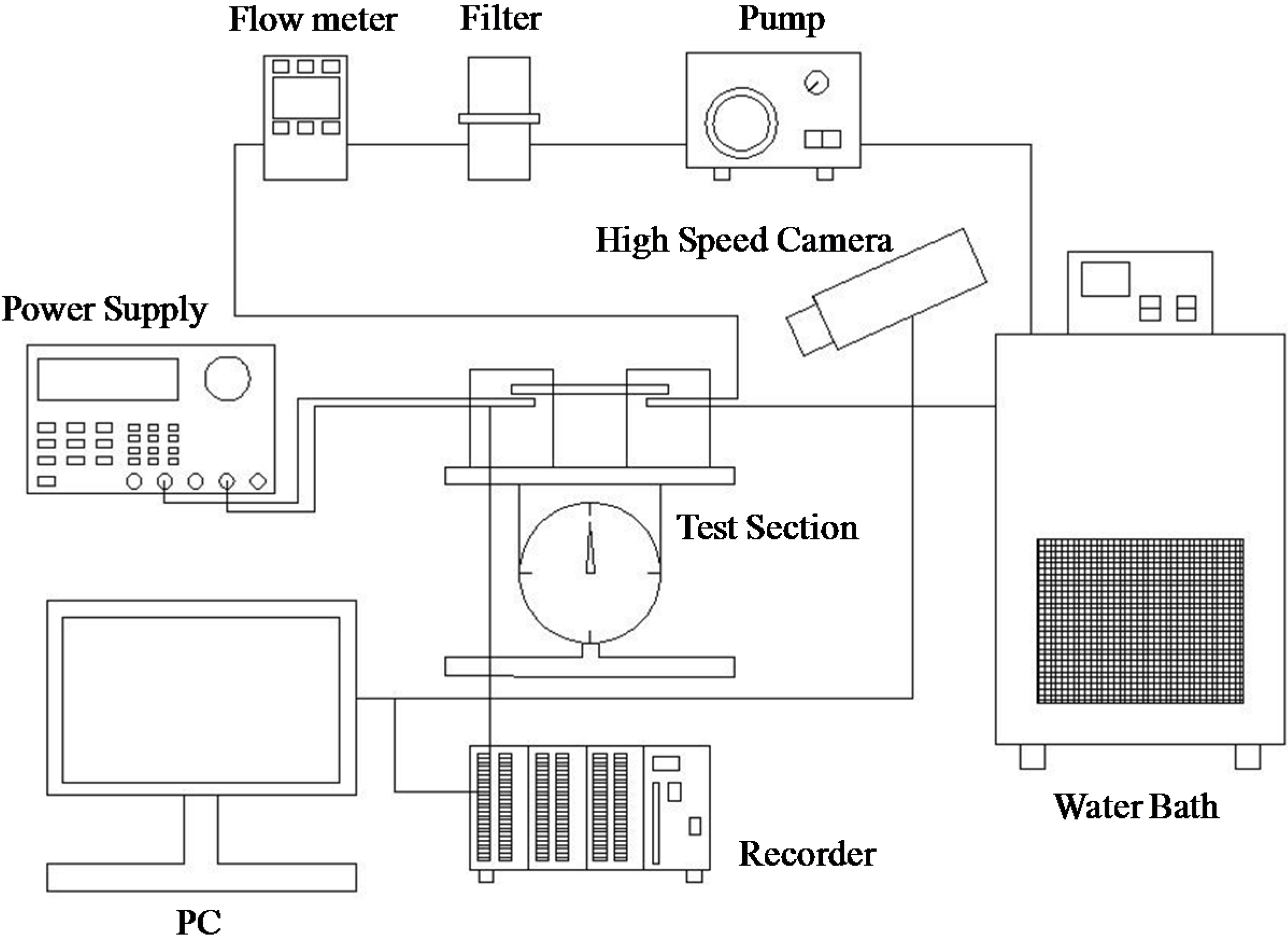
A schematic of the apparatus used in the µPHP experiment is shown in
Figure 1. In addition to the µPHP sample, the experimental design involved an evaporator section; a water loop, which served as a condenser; measurement devices; and a data-acquisition system. The evaporator section was composed of a copper block (10 × 11 mm), which heated the µPHP by providing electric power from a power supply connected to the heater embedded in the copper block. To minimize heat loss from the heater to the environment, a Bakelite board that had low thermal conductivity was installed beneath the copper block. Regarding the water loop, a water stream for cooling the µPHP was maintained at a low temperature by using a thermostat, and the flow rate was measured using a flow meter.
Figure 1.
Schematic of the experimental set up.
Figure 1.
Schematic of the experimental set up.
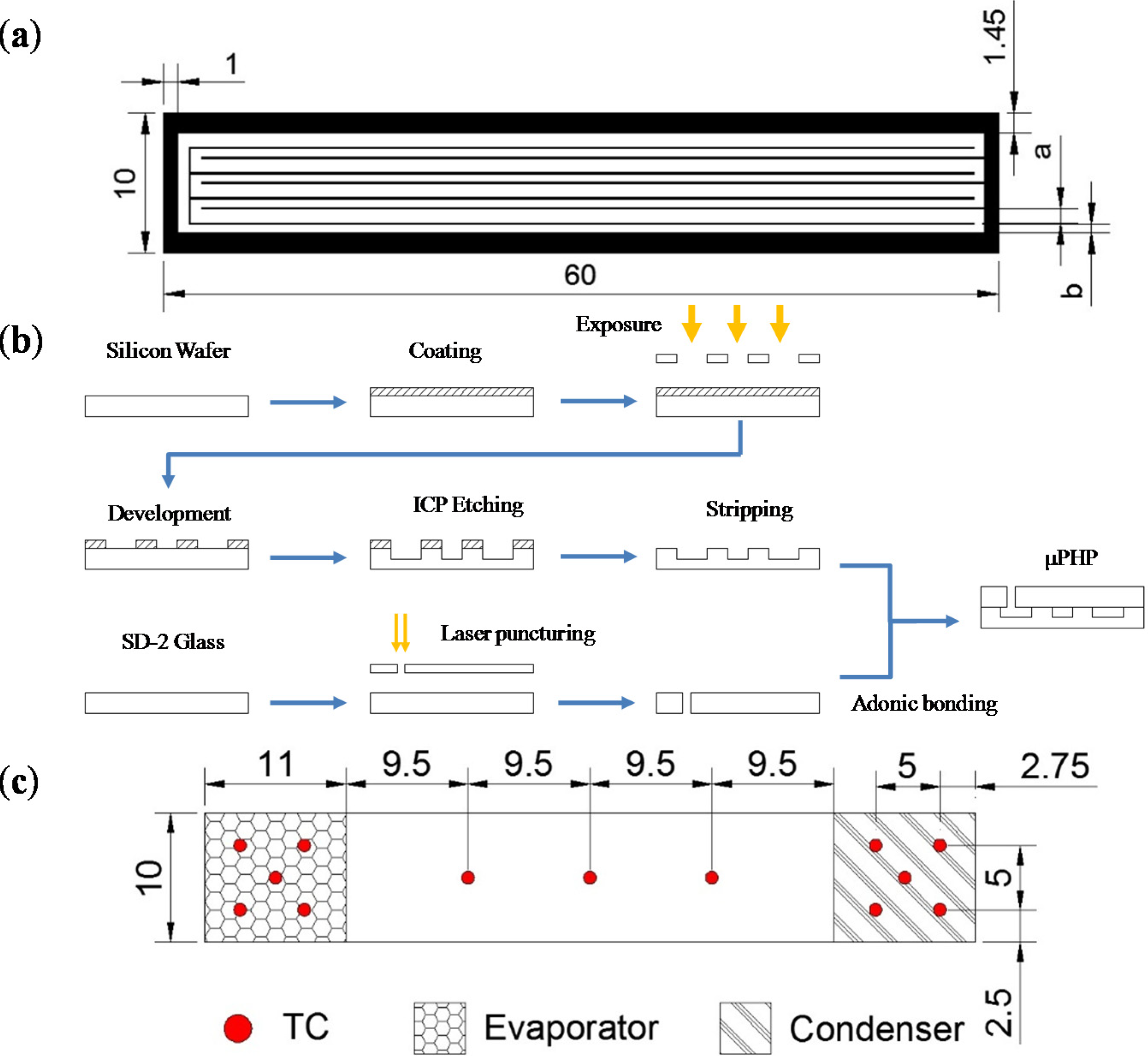
In this study, two μPHPs, one containing uniform channels and one containing nonuniform channels, were fabricated and tested. Detailed geometries and dimensions of the tested μPHPs are shown in
Figure 2a. The μPHPs were composed of silicon and glass wafers and exhibited an overall size of 60 × 10 × 1.25 mm and eight parallel rectangular channels. The cross-sectional area of each channel in the μPHP containing uniform channels was 0.8 × 0.25 mm, whereas the cross-sectional area of the channel in the other μPHP was 0.6 × 0.25 mm or 1.0 × 0.25 mm. The test sample was fabricated using DRIE after performing photolithography once, and a filling hole on the glass wafer was drilled using laser machining. The silicon wafer was anodically bonded to the glass wafer to achieve the μPHP sample shown in
Figure 2b. Before the evacuation of non-condensable gas in the μPHP, the working fluid, HFE-7100, was charged into a filling tube which was attached to the μPHP sample via a connecting valve. The degasing of the system was carried out by a rotary vane pump (Alcatel Pascal 2015SD) with the vacuum pressure of the system being lowered to 10
−4 torr and remained unchanged for over 6 h when it was connected to the μPHP. Then the working fluid was charged into the system once the valves connected to μPHP were opened. The filling rate was calculated by the difference of weight between before and after filling working fluid. After filling the μPHP with the working fluid and sealing the fluid filling port, the μPHP was oriented either horizontally or vertically and tested using several power inputs ranging from 2 to 7 W. The aforementioned μPHP was located above a well-fitted piece of Bakelite. Transparent glass was fitted on the top of the test section to enable flow visualization. Observations of the flow patterns were conducted using images recorded by a high-speed camera (HiSpec 1, Fastec Imaging, San Diego, CA, USA) that could be placed at any position above the square channel.
Thermocouples were used to measure the surface and fluid temperature. A total of 13 T-type thermocouples were placed underneath the test section to measure the average surface temperature, and two additional thermocouples were used to record the inlet and outlet temperatures of the cooling water in the condenser. The thermocouples were distributed below the surface of the test section, as schematically shown in
Figure 2c. These data signals were individually recorded and then averaged. During the isothermal test, the variation in these thermocouples was within 0.2 °C. In addition, all the thermocouples were precalibrated using a quartz thermometer that had a precision of 0.01 °C. The calibrated thermocouples had an accuracy of 0.1 °C. All the data signals were collected and converted using a data acquisition system (a hybrid recorder, Yokogawa MX-100, Tokyo, Japan). The data acquisition system then transmitted the converted signals through an Ethernet interface to the host computer for further operation.
Figure 2.
(a) Detailed dimensions of the micro pulsating heat pipes (μPHPs) (uniform microchannel: a = b = 0.8 mm; non-uniform microchannel: a = 1.0 mm, b = 0.6 mm). (b) Fabrication processof the μPHPs. (c) Schematic of the thermocouple locations of the μPHP (unit: mm).
Figure 2.
(a) Detailed dimensions of the micro pulsating heat pipes (μPHPs) (uniform microchannel: a = b = 0.8 mm; non-uniform microchannel: a = 1.0 mm, b = 0.6 mm). (b) Fabrication processof the μPHPs. (c) Schematic of the thermocouple locations of the μPHP (unit: mm).
3. Results and Discussion
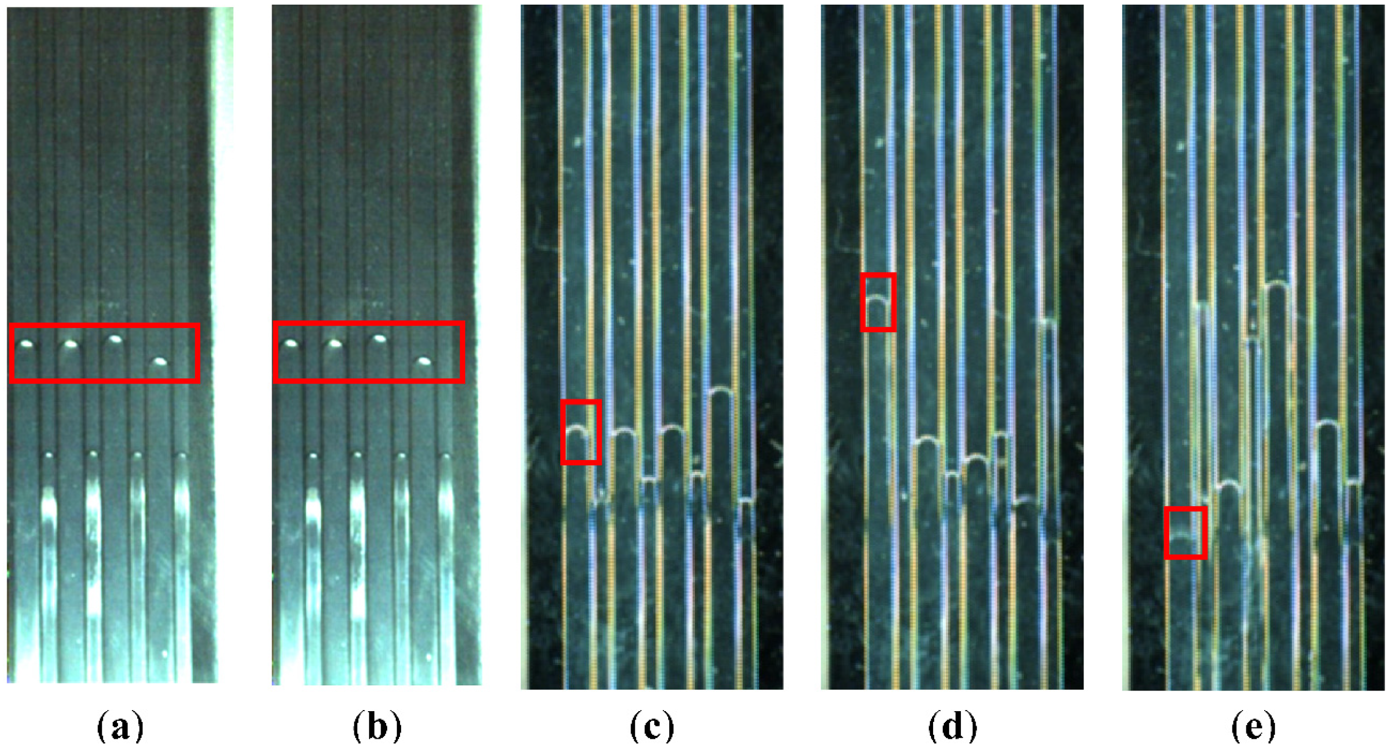
To examine the effects of operating conditions on the performance of μPHPs, various input powers and orientations were tested. The μPHPs containing uniform and nonuniform channels were charged at charge ratios of 59.3% and 61.5%, respectively, by using HFE-7100 as the working fluid. The horizontally and vertically oriented μPHPs, the condensation region of which was located at the upper end, were tested. During the experiments, the input power was increased incrementally from 2 to 7 W to record the junction temperature response of the μPHPs and observe the two-phase flow in the μPHPs at various input powers. Pictures showing the two-phase flow in the horizontally oriented μPHP containing nonuniform channels are shown in
Figure 3. The vapor/liquid interface in the μPHP, marked by a red rectangle in
Figure 3a,b, exhibited no oscillating motion until a higher input power of 7 W was provided, as shown in
Figure 3c–e. Excluding the case shown in
Figure 3c–e, the measured junction temperature increased considerably when the heating power increased, and no marked start-up phenomena were observed for the horizontally oriented μPHPs regardless of the microchannel type. This start-up failure of the horizontally oriented μPHP having fewer turns occurred because of the lack of assistance from gravity [
18]. Therefore, using nonuniform channels to introduce additional unbalancing capillary force and adjust the flow resistance facilitates the recover of lost gravitational force under certain operating conditions, as proposed by Chien
et al. [
9].
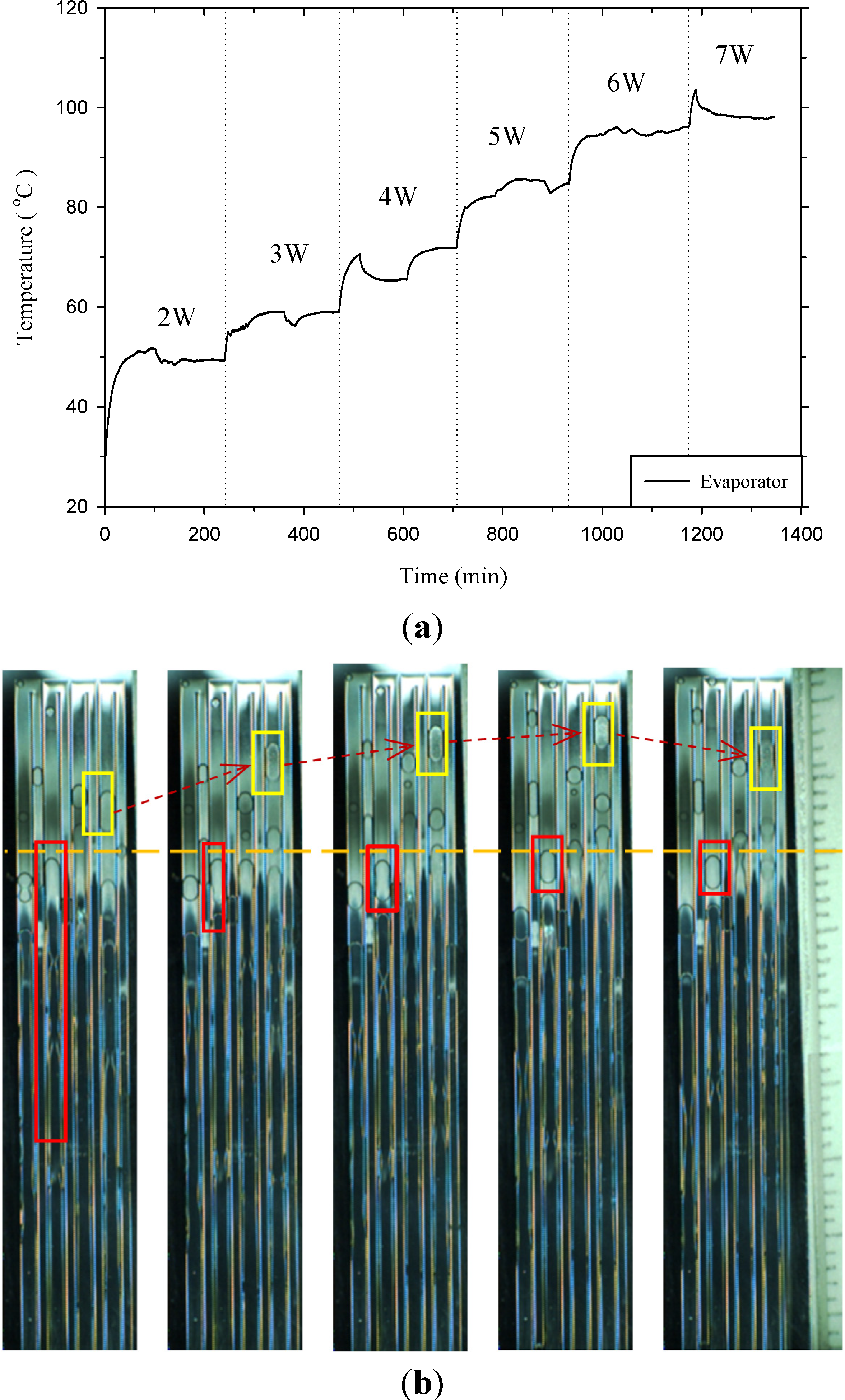
By contrast, in the vertical arrangement, the μPHPs containing uniform and nonuniform channels both demonstrated a marked start-up phenomenon, as shown in
Figure 4 and
Figure 5. The junction temperature variation shown in
Figure 4a and
Figure 5a and the oscillating motion of vapor slugs in the μPHPs shown in
Figure 4b and
Figure 5b indicate that the junction temperature variation in the evaporator of the μPHP containing nonuniform channels was more unstable than that in the evaporator of the other μPHP. The junction temperature in the evaporator of the μPHP containing nonuniform channels increased at heating powers of 5 and 6 W, but substantially decreased at a heating power of 7 W, as shown in
Figure 5a. Because the slug in the vertically oriented μPHPs started to oscillate, which was facilitated by gravitational force, the thermal resistance was reduced when the μPHP was oriented vertically.
Figure 3.
Pictures showing the fluid flow in a horizontally oriented μPHP having a nonuniform channel at (a) 0 s and (b) 0.04 s at an input power of 2 W; and at (c) 0 s, (d) 0.067 s, and (e) 0.134 s at an input power of 7 W.
Figure 3.
Pictures showing the fluid flow in a horizontally oriented μPHP having a nonuniform channel at (a) 0 s and (b) 0.04 s at an input power of 2 W; and at (c) 0 s, (d) 0.067 s, and (e) 0.134 s at an input power of 7 W.
Figure 4.
(a) Time vs. junction temperature variation of the evaporator, and (b) fluid flow at different time instants measured in increments of 0.033 s of a vertically oriented μPHP having uniform channels and an input power of 4 W.
Figure 4.
(a) Time vs. junction temperature variation of the evaporator, and (b) fluid flow at different time instants measured in increments of 0.033 s of a vertically oriented μPHP having uniform channels and an input power of 4 W.
The two pictures on the left in
Figure 4b show that the indicated vapor/liquid interface in the μPHP, which operated at an input power of 4 W, moved toward the condensing region and then the stretched vapor slug made a U-turn into an adjacent channel as it reached the end of the microchannel, as shown in the third picture in
Figure 4b. This slug movement and the turn at the end of the channel can be observed in various microchannels at different times, as shown by the marked region in the remaining pictures in
Figure 4b. Similar vapor slug oscillation can also be observed in the μPHP containing nonuniform microchannels. At 4 W, the vapor slugs marked by a yellow rectangle and a red rectanglein
Figure 5b moved upward slightly toward the condensing section and then moved downward. The vapor slugs shown in
Figure 5b moved within a shorter distance compared with those shown in
Figure 4b at an identical input power.
Figure 5.
(a) Time vs. junction temperature variation of the evaporator. (b) Fluid flow at different time instants measured in increments of 0.05 s of a vertically oriented μPHP having nonuniform channels and an input power of 4 W.
Figure 5.
(a) Time vs. junction temperature variation of the evaporator. (b) Fluid flow at different time instants measured in increments of 0.05 s of a vertically oriented μPHP having nonuniform channels and an input power of 4 W.
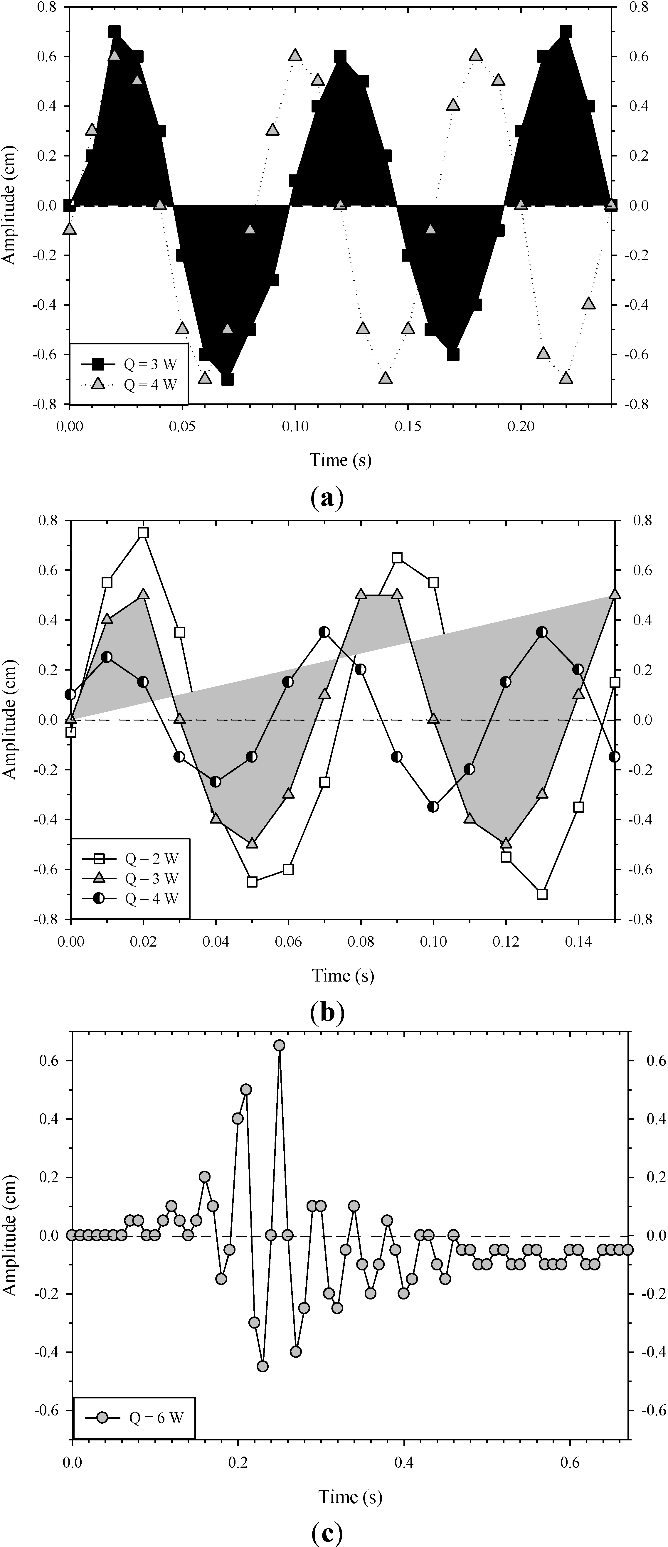
To analyze the vapor slug movement quantitatively, the time
vs. displacement of a vapor slug in both the uniform and nonuniform channels of a vertically oriented μPHP was plotted, as shown in
Figure 6. The displacement of a vapor slug was defined as the position of the liquid/vapor interface of a vapor slug in a single channel relative to a baseline, as indicated by the orange dashed line in
Figure 5b. In addition, the positive displacement shown in
Figure 6 indicates that the vapor slug moved upward. As the heating power increased, the frequency of the vapor slug oscillation considerably increased and the displacement of the vapor slug was reduced, as shown in
Figure 6a,b. In contrast to the results shown in
Figure 6a, the slug displacement in
Figure 6b was lower at input powers of 3 W and 4 W. The lower oscillating displacement shown in
Figure 6b could have been the result of the adjacent microchannel being too narrow to allow the vapor slug in the 1.0-mm-wide microchannel to easily make a U-turn into the narrow 0.6-mm-wide microchannel because the input power was not sufficiently high, in contrast to the cases in which 3 W and 4 W were used, as shown in
Figure 6b. The vapor slug marked by a yellow rectangle in
Figure 5b stopped moving toward the turn and began to move downward in the fourth picture of
Figure 5b. However, the unusual phenomenon of vapor slug displacement in the vertical μPHP containing nonuniform channels was observed; the displacement substantially decreased as the heating power increased, and periodic “start-stop” behaviors were observed at input powers of 5 W and 6 W, as shown in
Figure 6c. Subsequently, a further increase in heating power to 7 W caused the vapor slug in the μPHP to pulse intermittently, and the displacement was considerably larger (approximately 2 cm). Therefore, the thermal performance was highly enhanced at the heating power of 7 W. This could be a major cause of the relatively low junction temperature at an input power of 7 W shown in
Figure 5a. This indicates that the driving force behind the oscillation of fluid flow in the μPHP containing nonuniform microchannels requires time to increase as the input power increases.
Figure 6.
Time vs. displacement of a vapor slug in the vertical μPHP containing (a) uniform channels and input powers of 3 to 4 W; (b) nonuniform channels and input powers of 2 W, 3 W, and 4 W; and (c) nonuniform channels and an input power of 6 W.
Figure 6.
Time vs. displacement of a vapor slug in the vertical μPHP containing (a) uniform channels and input powers of 3 to 4 W; (b) nonuniform channels and input powers of 2 W, 3 W, and 4 W; and (c) nonuniform channels and an input power of 6 W.
4. Conclusions
μPHPs, which were fabricated using DRIE and anodic bonding and charged with HFE-7100, were either horizontally or vertically oriented and tested using several heating powers. Both visual observations and temperature measurements were recorded. The relative performance of the two μPHPs, one of which contained uniform rectangular channels and one contained nonuniform rectangular channels, was compared at various heating powers ranging from 2 to 7 W. The width of each channel was 0.8 mm in the μPHP containing uniform channels, whereas the width of each channel was either 1.0 mm or 0.6 mm in the other μPHP. The charge ratios for the μPHPs containing uniform and nonuniform channels were 59.3% and 61.5%, respectively.
The results indicated that when the μPHPs were operated horizontally at a heating power ranging from 1 to 7 W, the two μPHPs could not start the pulsating two-phase flow in the channels of the μPHPs, except when the μPHP containing nonuniform channels was tested at a heating power of 7 W. Unlike the failed start-up of the horizontally oriented μPHPs, the vertically oriented μPHPs demonstrated a marked start-up phenomenon facilitated by gravity in the process of inducing the vapor slugs to oscillate. In addition, the frequency of the sine-like oscillation displacement of a vapor slug increased as the input power increased for both μPHPs.


