Article

Microfabrication of a Novel Ceramic Pressure Sensor with High Sensitivity Based on Low-Temperature Co-Fired Ceramic (LTCC) Technology

1
Science and Technology on Electronic Test & Measurement Laboratory, North University of China, Tai Yuan 030051, China
2
Key Laboratory of Instrumentation Science & Dynamic Measurement, Ministry of Education, North University of China, Tai Yuan 030051, China
*
Authors to whom correspondence should be addressed.
Micromachines 2014, 5(2), 396-407; https://doi.org/10.3390/mi5020396
Submission received: 5 April 2014 / Revised: 12 June 2014 / Accepted: 13 June 2014 / Published: 24 June 2014
(This article belongs to the Special Issue Micro/Nano Fabrication)

Abstract

:
In this paper, a novel capacitance pressure sensor based on Low-Temperature Co-Fired Ceramic (LTCC) technology is proposed for pressure measurement. This approach differs from the traditional fabrication process for a LTCC pressure sensor because a 4J33 iron-nickel-cobalt alloy is applied to avoid the collapse of the cavity and to improve the performance of the sensor. Unlike the traditional LTCC sensor, the sensitive membrane of the proposed sensor is very flat, and the deformation of the sensitivity membrane is smaller. The proposed sensor also demonstrates a greater responsivity, which reaches as high as 13 kHz/kPa in range of 0–100 kPa. During experiments, the newly fabricated sensor, which is only about 6.5 cm2, demonstrated very good performance: the repeatability error, hysteresis error, and nonlinearity of the sensor are about 4.25%, 2.13%, and 1.77%, respectively.

1. Introduction

Ceramic has been widely used in microsystem applications owing to its inherent features, which include hermeticity, chemical inactivity, high temperature stability. Most micro-sensors such as pressure sensors, flow sensors, etc., are created using silicon material [1,2,3,4,5,6]. In recent years, however, low-temperature co-fired ceramic (LTCC) technology has been applied in various fields, including electrochemical devices, (bio)medical devices, pressure sensors, flow sensors, etc., [7,8,9,10]. And, there is growing interest in creating high-temperature pressure sensors using LTCC technology. In 2002, English, Allen, et al. [11,12] pioneered a wireless passive high-temperature pressure sensor based on LTCC technology; the sensitivity of that sensor can reach 150 kHz/bar. In 2009, Radosavljevic et al. [13,14] proposed a wireless embedded resonant pressure sensor, fabricated with standard LTCC technology that can operate in chemically aggressive environments. However, the sensitivity of that sensor is only 25.6 KHz/bar. In 2013, Xiong et al. [15] published their findings regarding an improved sensor based on LTCC technology; this sensor’s sensitivity reached 344 KHz/bar. Although LTCC integration technology optimized the fabrication process of the capacitance pressure sensor, the pressure-sensitive membrane, which is based on ceramic material, still exhibits the following disadvantages: (1) the sensitivity of the sensor is lower, which is caused by lack of toughness of the ceramic material; (2) the stiffness of the ceramic material is too high and affect the service life and performance of the sensitive membrane; (3) the fabrication process results in some deformations in the LTCC sensitive membrane, and these deformations cause interference in the theoretical model calculations and the practical application of the sensor; and (4) the thickness of the LTCC caste tape (type: Dupont 951) that is used to fabricate the sensor is limited, and we cannot decrease the thickness for demand because the thinner sensitive membrane is hard to form.
In order to solve the above problems and improve the performance of the sensor, we propose a novel LTCC ceramic pressure sensor preparation method that utilizes the 4J33 iron-nickel-cobalt alloy for the sensitive membrane materials. The 4J33 iron-nickel-cobalt alloy (as the sensitive membrane) and the ceramic substrate (fabricated using LTCC technology) are welded closely together using parallel seam sealing technology. At last, the fabricated sensor is tested wirelessly in room temperature environments, and a set of pressure studies verify the sensitivity of the sensor.

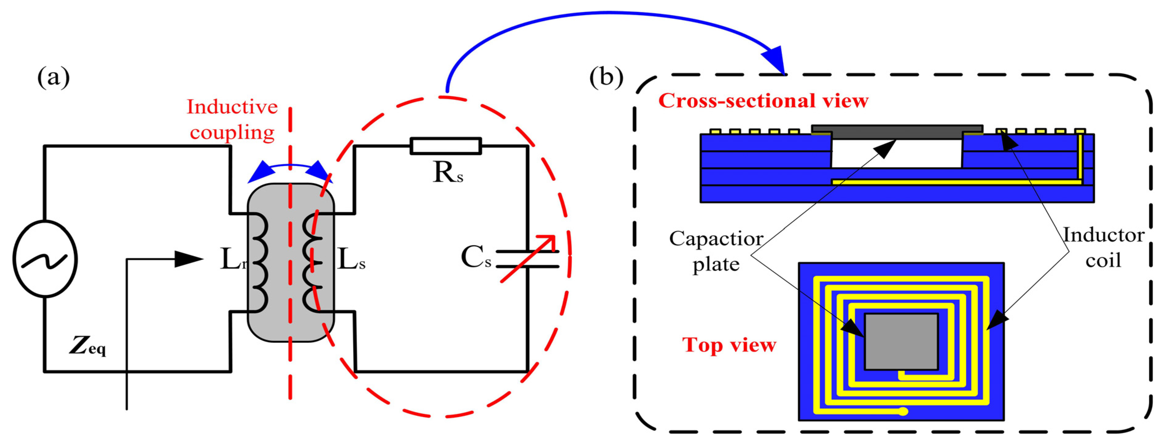
2. Measurement Principle and Structure Design

A wireless passive resonant telemetry scheme is applied, and the sensor can faithfully register pressure variations using corresponding electrical characteristic change, which are obtained from the external reader antenna through a wireless coupling link. The equivalent circuit schematic of the sensing system is shown in Figure 1a and the equivalent impedance viewed from the test antenna can be devised using circuit analysis as in [16,17,18].
Micromachines 05 00396 i001
where f, fs are the excitation frequency and resonant frequency of the sensor, respectively. k is the coupling coefficient, and Qs is the quality factor of the sensor. The operating principle of the sensor is that the change in pressure will be translated into a variation in the sensor’s resonant frequency, and the pressure will be precisely detected by monitoring the change in the resonant frequency of the sensor.
Figure 1. (a) Wireless passive sensing concept; (b) Pressure sensor design schematics.
Micromachines 05 00396 g001
The principle diagram of the proposed pressure sensor is shown in Figure 1b, and the sensor comprises a fixed inductance L and a flexible capacitance C integrated on the ceramic substrate connected to form a series resonance circuit. When the outside air pressure is different from that in the sealed cavity, the pressure-sensitive membrane deformation occurs, which leads to changes in the embedded capacitance C and LC resonance frequency shift. The resonant frequency of the sensor can be expressed as follows:
Micromachines 05 00396 i002
where Ls and Cs are the inductance and capacitance of the sensor, respectively. The electrical characteristics of the sensor can be determined by using the established models, where the electrical inductance of such a square planar spiral coil is calculated as [11,12]:
Micromachines 05 00396 i003
where n is the number of turns of the inductor coil, din is the inner diameter, dout is the outer diameter, and u0 is the permeability of vacuum. In addition, when pressure is applied on the sensitive membrane of the sensor, the electrical capacitance of the sensor can be expressed as:
Micromachines 05 00396 i004
where tg is the depth of the cavity, ts is the thickness of the ceramic tape, ε0 is the free space permittivity, and εr is the relative dielectric constant. d0 is the center deflection of the membrane when the pressure is applied on the circular plate, and the deflection is small when compared with the plate thickness (d0 << tm). d0 can be expressed as:
Micromachines 05 00396 i005
where a is the radius of the circular electrode, tm is the thickness of the alloy membrane, P is the atmospheric pressure outside the sensor, E is the Young’s modulus, and v is the Poisson’s ratio. In terms of the aforementioned discussion, the specific parameters of the sensor are listed in Table 1.
Table 1. Parameters of the sensor designed.
SymbolParametersValue
a1Side length of the sensor plane26 mm
a2Side length of capacitance metal6.5 mm
dinDiameter of inner inductor 8 mm
doutDiameter of outer inductor 22 mm
l1Width of coil turns0.2 mm
l2Distance between neighbor coils 0.2 mm
nNumber of turns of the inductor coil18
tgHeight of the embedded cavity0.1 mm
tmHeight of the sensitive membrane0.08 mm

3. Fabrication Processes

The 4J33 iron-nickel-cobalt alloy (Kangsheng Corporation, Shanghai, China) is an elastic material. When used as a sensitive membrane, the 4J33 iron-nickel-cobalt alloy provides some advantages: (1) compared with the ceramic material, the 4J33 iron-nickel-cobalt alloy material has high toughness, high reliability, and high sensitivity; (2) The 4J33 iron-nickel-cobalt alloy has lower Young’s modulus than ceramic, which is only about 139 GPa, and similar coefficient of thermal expansion (CTE), which is about 6–7 ppm/C; (3) the linear expansion coefficient of the 4J33 iron-nickel-cobalt alloy material is similar to that of the LTCC material in high-temperature environments, and this can meet the demand for high-temperature applications of the sensor; (4) the 4J33 iron-nickel-cobalt alloy membrane can be processed as very thin and flat, which can significantly improve the performance of the sensitive membrane; and (5) the 4J33 iron-nickel-cobalt alloy material has good compatibility with the LTCC material and can combine well with LTCC material, which will ensure that the cavity of the sensors is sealed.
In order to fabricate a sensor using the LTCC material and 4J33 iron-nickel-cobalt alloy, a novel process flow was adopted and implemented. The experiment proved that this fabrication process is feasible. The details are as follows:
a
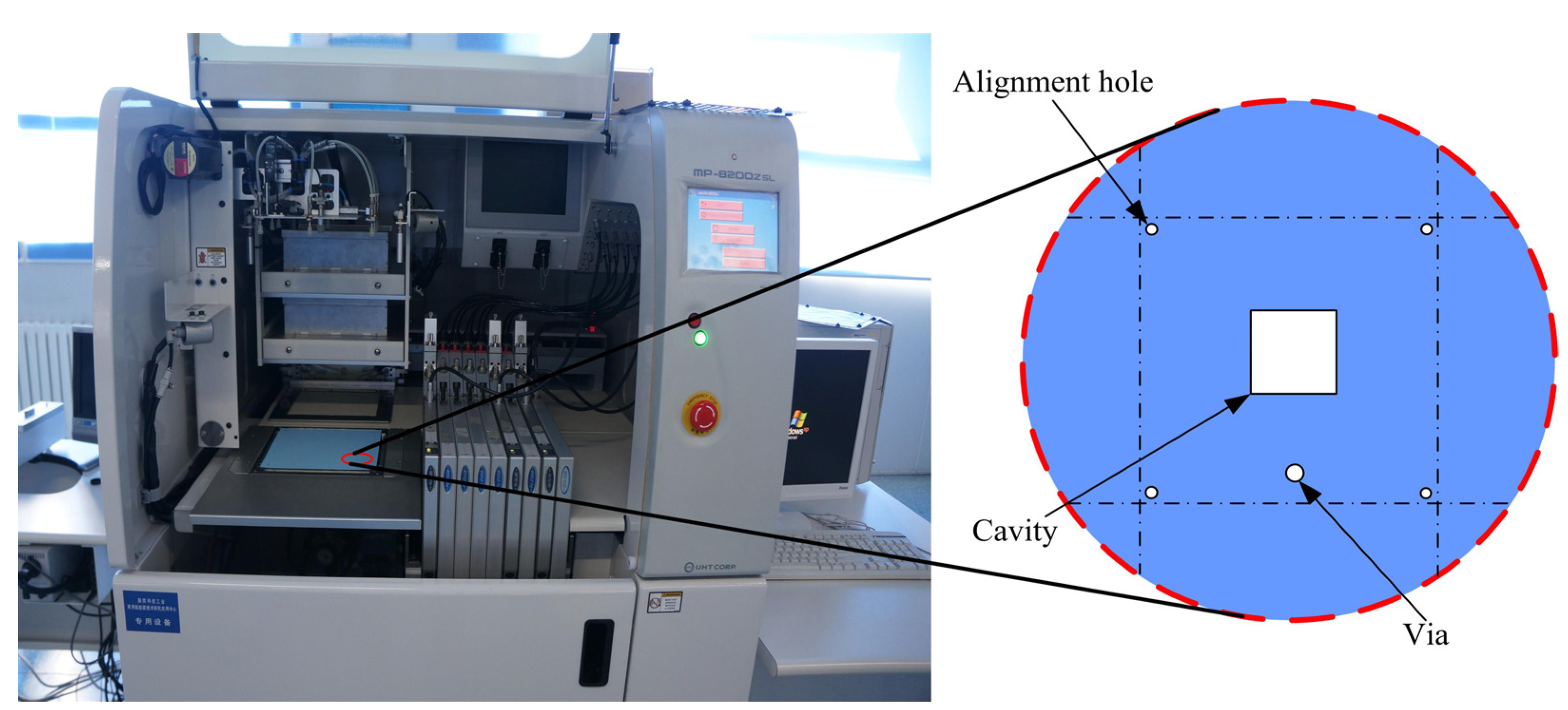
Drilling: The Dupont 951 cast tapes (DuPont, Wilmington, DE, USA) were cut into 6-inch squares, and the cast taps were put in a 80 °C drying oven for approximately 30 min for pretreatment. The alignment hole, via, and capacitance cavity of the sensor were created using the punching machine (KEKO, Zuzemberk, SI, Slovenia), as shown in Figure 2. The alignment hole was used to laminate the cast tapes accurately, and the via was used to establish a metal connection between the ceramic cast layers.
Figure 2. Drilling bedstand.
Micromachines 05 00396 g002
b
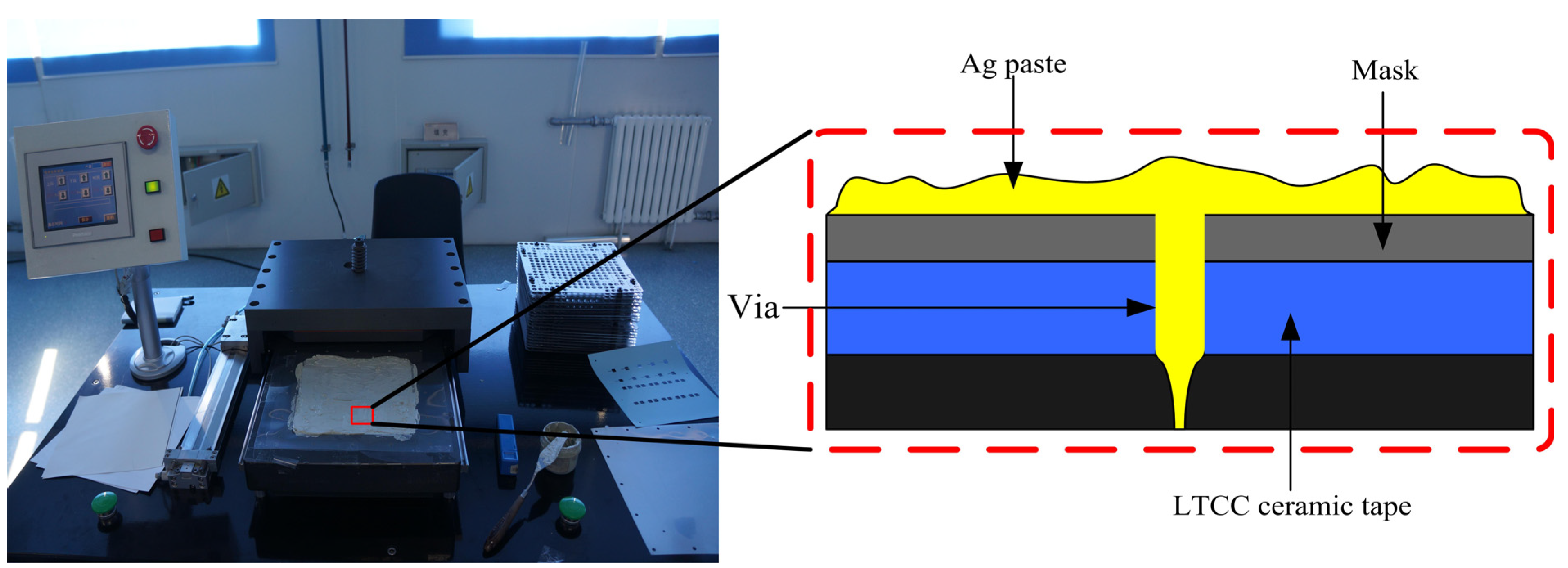
Filling: After the drilling process was completed, the via was filled with DuPont 6142D silver paste (DuPont, Wilmington, DE, USA) in the filling machine (KEKO, Zuzemberk, SI, Slovenia), as shown in Figure 3. The via provides the metal interconnection between the inductance and capacitance of the ceramic tape layers.
Figure 3. Filling bedstand.
Micromachines 05 00396 g003
c
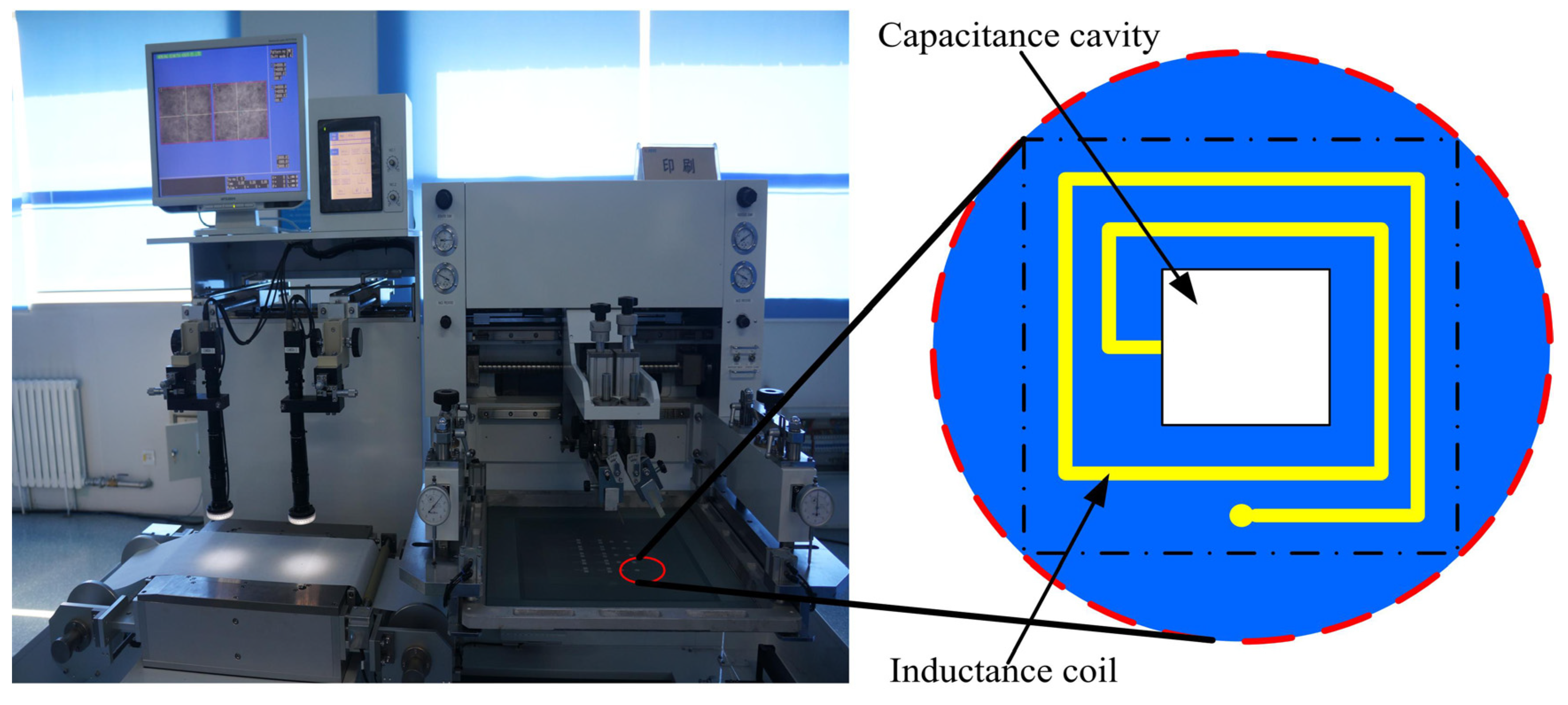
Screen printing: After the filling process is completed, the screening-printing machines (KEKO, Zuzemberk, SI, Slovenia) was implemented for the inductance coil and capacitor plates using silk-screen printing, as shown in Figure 4. The mesh count of the printing plate is set to 250, which is conducive to the printing of the inductance coil. As the tapes and patterning coincide at a fixed position on the screen-printing plate, this ensured that they were aligned. Then, the metal plates (as a capacitor plate) and surrounding spiral metal wires (as a planar inductor) were screen-printed on the tapes according to the previous design. After screen printing, the ceramic tapes with 6142D Ag paste were put in a drying oven at 120 °C in air for about 5 min for thermal treatment.
Figure 4. Screening bedstand.
Micromachines 05 00396 g004
d
Laminating: The ceramic tape layers were placed in the isostatic pressing laminating machine (KEKO, Zuzemberk, SI, Slovenia) to be laminated, as shown in Figure 5a. All the ceramic tape layers were stacked together according to the design requirement. The ceramic tape layers were laminated at a pressure of 21 MPa for 15 min. Then, the ceramic tape layers were tightly bonded together to form a complete ceramic substrate that could not be separated into individual layers.
Figure 5. Laminating machine.
Micromachines 05 00396 g005
e
Co-firing: After the laminating process, the ceramic substrate was put in a drying oven at 70 °C for approximately 10 min for thermal treatment. The ceramic substrate was cut, using a sharp blade, to create some signal ceramic substrates. Then, the ceramic substrates were sintered in the box furnace at a peak temperature of 850 °C for 50 min to melt the glass matrix, with a total firing time of about 750 min to cure the ceramic substrates. The specific sintering cure is shown in Figure 6.
Figure 6. Temperature process control cure.
Micromachines 05 00396 g006
f
Parallel seam sealing: After the co-firing, the ceramic tapes formed an integrated ceramic structure, as shown in Figure 7a. The ceramic substrate is not a complete pressure sensor, and the capacitor cavity structure consists only of a capacitor plate. In order to make the 4J33 iron-nickel-cobalt alloy as the sensitive membrane, it was made into a manhole cover-type membrane through a cold-rolled, polishing fabrication process. Before the seam welding, the oxide, dirt, oil and other impurities on the surface of iron-nickel alloy were cleaned completely, and the 4J33 iron-nickel-cobalt alloy were put in a 800 °C vacuum furnace for approximately 40 min for pretreatment. Au was plated on the parts between the ceramic substrates and the alloy membrane, which is beneficial to the metal membrane and ceramic substrate were closely linked together using parallel seam sealing machine (Arbor instrument Corporation, Qingdao, China). And, the seam welding process is in the vacuum environments, which can reduce the oxygen content and prevent the sensor from the influence of the external environments. During the seam welding process, the welding pressure was controlled for about 8 N, which can make the ceramic and alloy contact closely.
After the sealing process, the preparation of the pressure sensor was completed with an LC series resonance circuit on the ceramic substrate, as shown in Figure 7b. When external pressure is applied to the sensitive membrane, the metal diaphragm will deflect as a function of the pressure.

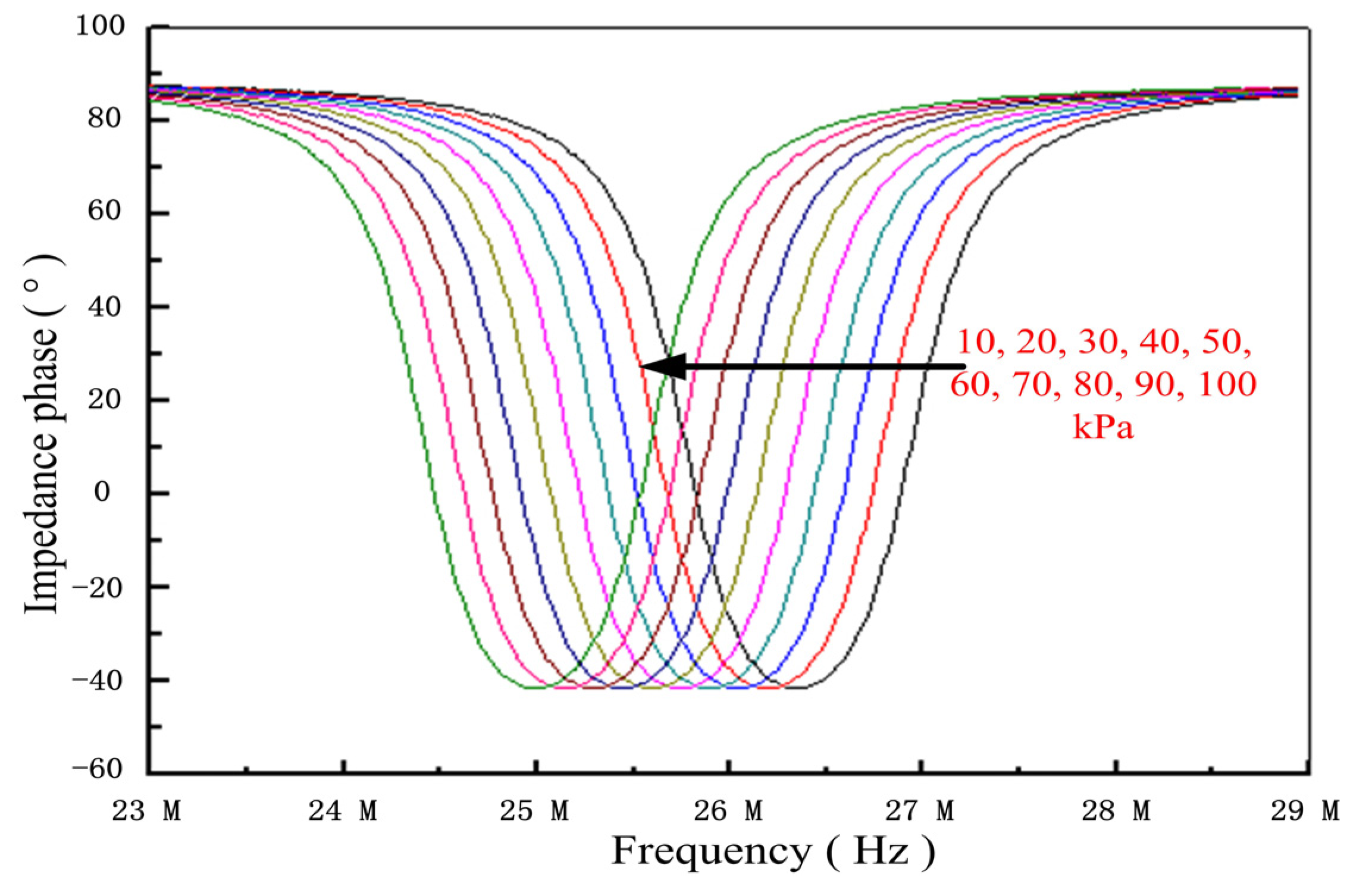
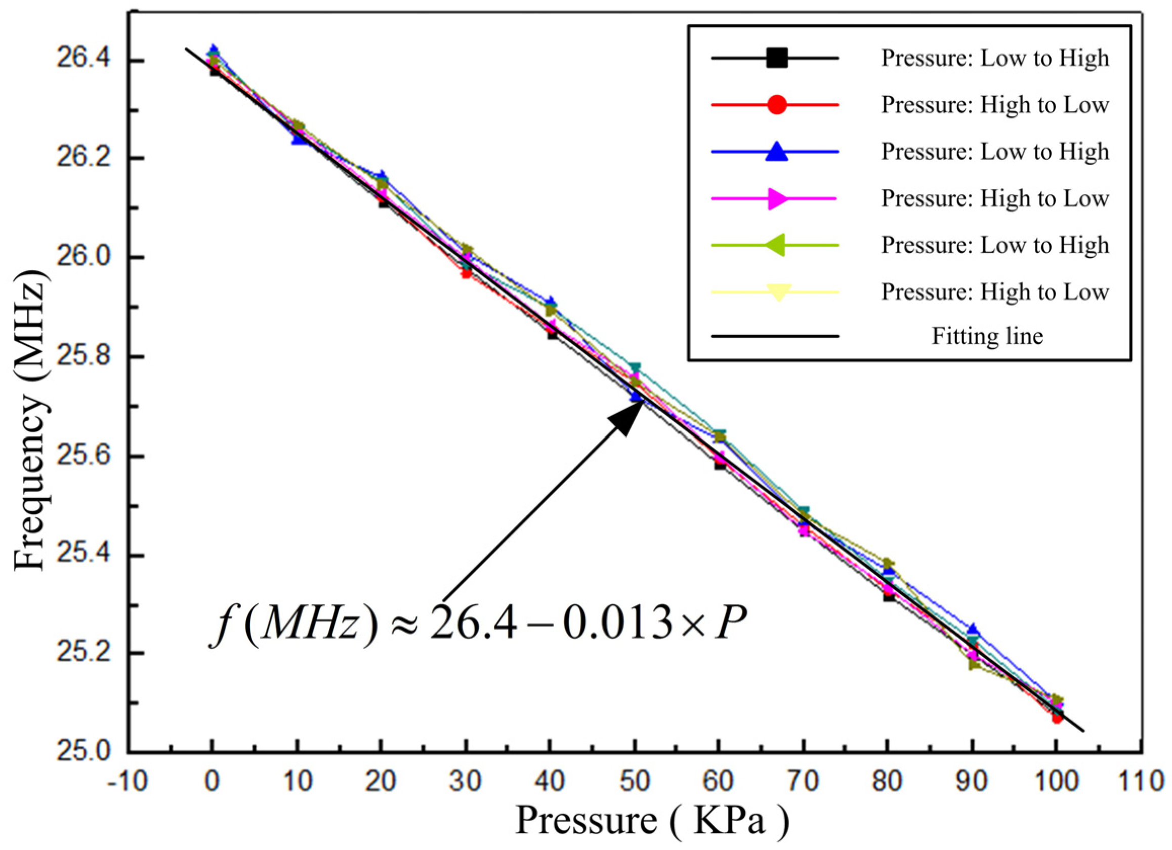
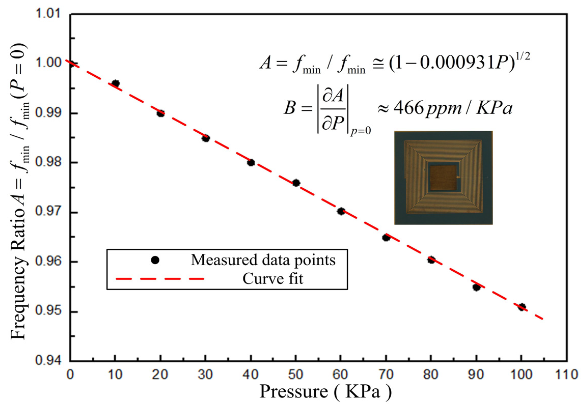
4. Results and Discussion

Figure 8 is the sensor’s sample measured by Surface Profilometer (KLA-TENCOR Corporation, San Jose, CA , USA). The maximum deformation of the sensitive membrane is only about 3 μm, which is flat and smaller than the deformation in the latest report of LTCC sensors researched by Xiong (2013) [15]. The reason is that the sensitive membrane fabricated in ceramic material will deform during high-temperature co-firing and laminating, and the deformation of the membrane will increase as the cavity dimension increases. By contrast, the sensitive membrane of the sensor proposed in this paper is fabricated using parallel seam sealing technology, which will avoid the deformation of the membrane that results from high-temperature co-firing and laminating.
Figure 7. (a) Photo of the ceramic substrate without complete sealed cavity; and (b) Photo of the sensor sample.
Micromachines 05 00396 g007
Figure 8. Sensitive membrane sample with 4J33 iron-nickel-cobalt alloy.
Micromachines 05 00396 g008
In order to analyze the sensor’s sensitivity, the impedance phase of the sensor was wirelessly detected using an Agilent impedance analyzer E4991A. A set of pressure tests of the sensor was carried out in the pressure test platform, and the pressure signal in the test vessel was wirelessly monitored as the impedance phase changed. Figure 9 and Figure 10 show these test results.
Figure 9. Impedance phase curves versus pressure.
Micromachines 05 00396 g009
Figure 10. Resonant frequency of the sensor versus pressure.
Micromachines 05 00396 g010
From Figure 9, we observe that the sensor has a good pressure response and that the phase curve of the sensor moves to the left as the pressure increases. After many repeated pressure experiments, the fabricated sensor demonstrated a greater responsivity than the previous LTCC pressure sensor and a linear characteristic response between normal atmospheric pressure and 100 KPa, as shown in Figure 10. The responsivity of the sensor is approximately 13 KHz/KPa. From the measurement results, we can conclude that the repeatability error, hysteresis error, and the nonlinearity of the sensor are about 4.25%, 2.13%, and 1.77%, respectively.
A can be defined as frequency ratio, and B can be defined as pressure sensitivity. A and B can be used to characterize the sensor as a function of pressure, as follows:
Micromachines 05 00396 i006
Micromachines 05 00396 i007
From Figure 11, we conclude that the performance of the new sensor is better than the performance of the LTCC sensors fabricated by Xiong (2013) [15]. The reasons are that the 4J33 iron-nickel-cobalt alloy metal membrane performs better than the LTCC material, and that the capacitor plate of the sensor fabricated by the 4J33 iron-nickel-cobalt alloy metal membrane is more sensitive to pressure.
In the future, the sensitivity of the sensor can be optimized by increasing the dimensions of the capacitance plate and reducing the thickness of the sensitive membrane.
Figure 11. Relative change in sensor’s resonant frequency versus pressure.
Micromachines 05 00396 g011

5. Conclusions

This paper mainly demonstrates a novel fabrication technology for improving the sensitivity of the sensor. To improve the performance of the sensor, the series capacitor plates and inductance coil are integrated on the ceramic substrate using LTCC technology. The 4J33 iron-nickel-cobalt alloy (as the sensitive membrane) and the fabricated ceramic substrate are closely welded together using parallel seam sealing technology. The experimental results showed that the fabricated sensor achieves a linear characteristic response between normal atmospheric pressure and 100 KPa. The sensitivity of the sensor reaches as high as 466 ppm/KPa. The repeatability error, hysteresis error, and the non-linearity of the fabricated sensor are very low—approximately 4.25%, 2.13%, and 1.17%, respectively.

Author Contributions

All works with relation to this paper have been accomplished by all authors’ efforts. The idea and design of the sensor were proposed by Chen Li and Qiulin Tan. Wendong Zhang designed the fabrication method of the sensor. The experiments of the sensor were completed with the help from Chenyang Xue, and Yunzhi Li gave significant guidance on the selection of metal sensitive membrane. At last, every segment relate to this paper is accomplished under the guidance from Jijun Xiong.

Acknowledgments

This work was supported by the Program for the Outstanding Innovative Teams of Higher Learning Institutions of Shanxi, Research Project Supported by Shanxi Scholarship Council of China (2013–2077), and the National Natural Science Foundation of China (No. 61335008).

Conflicts of Interest

The authors declare no conflict of interest.

References

  1. Khanna, P.K.; Hornbostel, B.; Burgard, M.; Schäfer, W.; Dorner, J. Studies on threedimensional moulding, bonding and assembling of low-temperature-cofired ceramics for MEMS and MST applications. Mater. Chem. Phys. 2005, 89, 72–79. [Google Scholar] [CrossRef]
  2. Jones, W.K.; Liu, Y.; Larsen, B.; Wang, P.; Zampino, M. Chemical structural and mechanical properties of LTCC tapes. Int. J. Microcircuits Electron. Packag. 2000, 23, 469–473. [Google Scholar]
  3. Lam, R.H.W.; Li, W.J. A digitally controllable polymer-based microfluidic mixing module array. Micromachines 2012, 3, 279–294. [Google Scholar] [CrossRef]
  4. Garraud, A.; Combette, P.; Courteaud, J.; Giani, A. Effect of the detector width and gas pressure on the frequency response of a micromachined thermal accelerometer. Micromachines 2011, 2, 167–178. [Google Scholar] [CrossRef]
  5. Kuo, J.T.W.; Yu, L.; Meng, E. Micromachined thermal flow sensors—A review. Micromachines 2012, 3, 550–573. [Google Scholar] [CrossRef]
  6. Silvestri, S.; Schena, E. Micromachined flow sensors in biomedical applications. Micromachines 2012, 3, 225–243. [Google Scholar] [CrossRef]
  7. Ibáñez-García, N.; Alonso, J.; Martínez-Cisneros, C.S.; Valdés, F. Green-tape ceramics. New technological approach for integrating electronics and fluidics in microsystems. TrAC Trend Anal. Chem. 2008, 27, 24–33. [Google Scholar] [CrossRef]
  8. Goldbach, M.; Axthlem, H.; Keusgen, M. LTCC-based microchips for the electrochemical detection of phenolic compounds. Sens. Actuators B 2006, 120, 346–351. [Google Scholar] [CrossRef]
  9. Golonka, L.J. Technology and applications of low temperature co-fired ceramic (LTCC) based sensors and microsystems. Bull. Pol. Acad. Sci. Tech. Sci. 2006, 54, 221–231. [Google Scholar]
  10. Sadler, D.; Changrani, R.; Roberts, P.; Chou, C.; Zenhausern, F. Thermal management of BioMEMS: Temperature control for ceramic-based PCR and DNA detection devices. IEEE Trans. Compon. Packg. Technol. 2003, 26, 309–316. [Google Scholar] [CrossRef]
  11. Fonseca, M.A.; English, J.M.; von Arx, M.; Allen, M.G. Wireless micromachined ceramic pressure sensor for high-temperature applications. J. Microelectromech. Syst. 2002, 11, 337–343. [Google Scholar] [CrossRef]
  12. Fonseca, M.A. Polymer/Ceramic Wireless MEMS Pressure Sensors for Harsh Environments: High Temperature and Biomedical Applications. Ph.D. Thesis, Georgia Institute of Technology, Atalanta, GA, USA, 2007. [Google Scholar]
  13. Radosavljevic, G.J.; Zivanov, L.D.; Smetana, W.; Maric, A.M.; Unger, M.; Nad, L.F. A wireless embedded resonant pressure sensor fabricated in the standard LTCC technology. IEEE Sens. J. 2009, 9, 1956–1962. [Google Scholar] [CrossRef]
  14. Radosavljevic, G.; Smetana, W.; Mari, A.; Zivanov, L.J.; Unger, M.; Stojanovi, G. Microforce Sensor Fabricated in the LTCC Technology. In Proceedings of the 27th International Conference on Microelectronics (MIEL 2010), Nis, Serbia, 16–19 May 2010; pp. 16–19.
  15. Xiong, J.; Li, Y.; Hong, Y.; Zhang, B.; Cui, T.; Tan, Q.; Zheng, S.; Liang, T. Wireless LTCC-based capacitive pressure sensor for harsh environment. Sens. Actuators A 2013, 197, 30–37. [Google Scholar] [CrossRef]
  16. Akar, O.; Akin, T.; Najafi, K. A Wireless batch sealed absolute capacitive pressure sensor. Sens. Actuators A 2001, 95, 29–38. [Google Scholar] [CrossRef]
  17. DeHennis, A.; Wise, K.D. A Double-Sided Single-Chip Wireless Pressure Sensor. In Proceedings of the 15th IEEE Micro-Electro-Mechanical Systems Conference, Las Vegas, NV, USA, 20 January 2002; pp. 252–255.
  18. Baldi, A.; Choi, W.; Ziaie, B. A self-resonant frequency-modulated micromachined passive pressure transensor. IEEE Sens. J. 2003, 2, 728–733. [Google Scholar] [CrossRef]

