1. Introduction
Fuel cells have been traditionally used for stationary power generation or in electrical vehicles, but miniaturized micro fuel cells (micro FC) have been, more recently, researched as a viable alternative to rechargeable batteries for applications, such as mobile phones, MP3 players, camcorders,
etc., due to the potentially higher energy density [
1,
2]. In order to compare a micro FC-based power source to traditional Li-ion batteries in portable applications, both the volume and weight of the fuel reservoir and the micro FC have to be taken into consideration. In micro FCs used for portable applications, operating temperatures are lower than in macro fuel cells (used in automotive and cogeneration technologies), and hence, the power density (per area) is lower, as well. To compensate, the small size of micro FCs should be utilized as much as possible: with smaller fuel cells, the per-volume power density increases. To achieve sufficient power density and voltage, a number of micro FCs should be stacked. There is an additional benefit of having multiple smaller fuel cells rather than one large one: to minimize the effect of defects in microfabrication, which is the same argument as the one used in the microelectronic industry to have a large number of chips per wafer.
One possible approach for adding and combining multiple micro FCs to a microfabricated power source is to concatenate them in a planar or co-planar structure (such as in [
3,
4,
5,
6,
7,
8,
9,
10,
11,
12,
13]), in which case there is no real stack, but rather a cluster of micro FCs placed laterally next to each other in the same plane. This approach is often used in microfabrication, because it will simplify either the placement and fabrication of gas interconnects or the placement and fabrication of electrical interconnects. However, it will not simplify the fabrication of both. This type of structure suffers from lateral ionic inter-cell conduction through the electrolyte (such as a proton exchange membrane, PEM) and has to be taken care of by patterning the electrolyte. Furthermore, it is often not desirable to have a planar structure, because of form factor restrictions. Finally, compared to vertical stacks, planar micro FC stacks have the disadvantage of being harder to isolate thermally due to a larger surface-to-volume ratio. Sustaining high temperatures is important for achieving high reaction rates and, thus, the high performance of a fuel cell. This thermal advantage of vertical
vs. planar micro FC stacks has been fully utilized in [
14], where two micro solid oxide fuel cells (SOFC) operating at 600 °C have been vertically stacked and thermally isolated.
Some examples of vertically stacked micro FC studies do exist [
14,
15,
16,
17]. In the macro world, vertically-stacked fuel cells are the norm, while planar stacks are almost unheard of. The reason for the predominance of planar stacks with microfabricated fuel cells is the structural overhead that electrical and fluidic interconnects impose on the design. In [
15], an attempt was made to reduce this overhead, by having a shared anode plate, where a single methanol channel serves as the flow field for two cathodes, whereas in [
14], the simplicity is a consequence of using a single-chamber configuration, where both the cathode and the anode are placed in the same container with fuel and oxidant. These designs are restricted to two cells per stack.
No such restriction in the number of stacked cells exists for the devices described in [
16,
17]. These micro FC stacks use a configuration known as “bipolar plates”, where the flow field plates are conductive and stacked in such a way as to add to the voltage of the cells. Both solutions take care of the distribution of reactants (oxidant and fuel) to all of the cells: in [
16], this was achieved by pumping, while in [
17], the cells are self-breathing and the liquid fuel is pumped by CO
2 bubble formation at the anode.
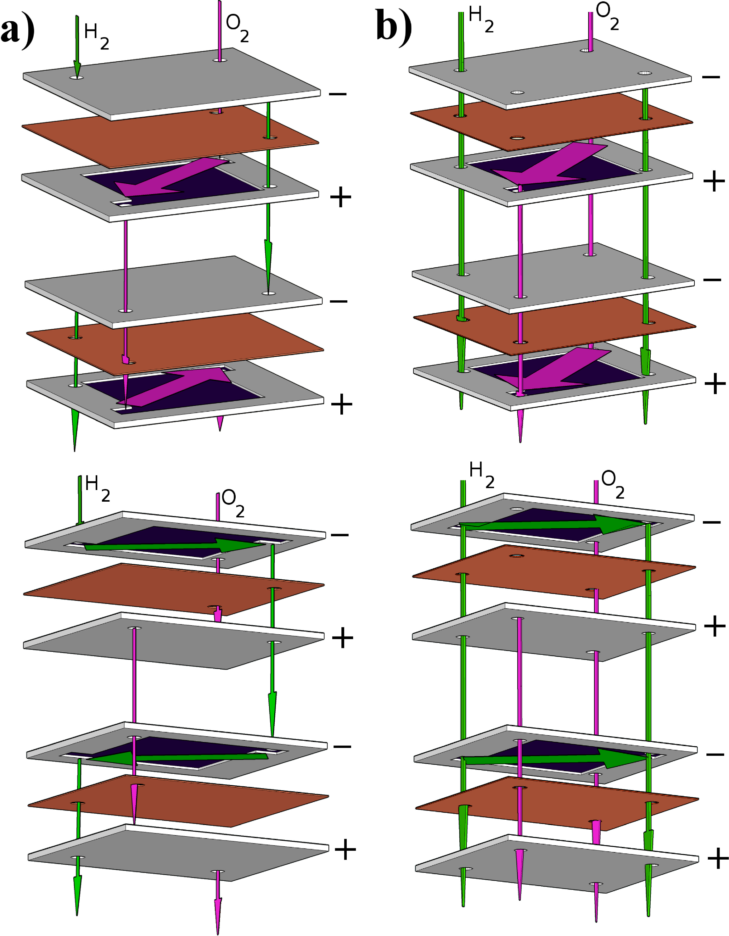
Our designs allow for theoretically unlimited numbers of fuel cells per stack. One of these designs uses the same flow topology as [
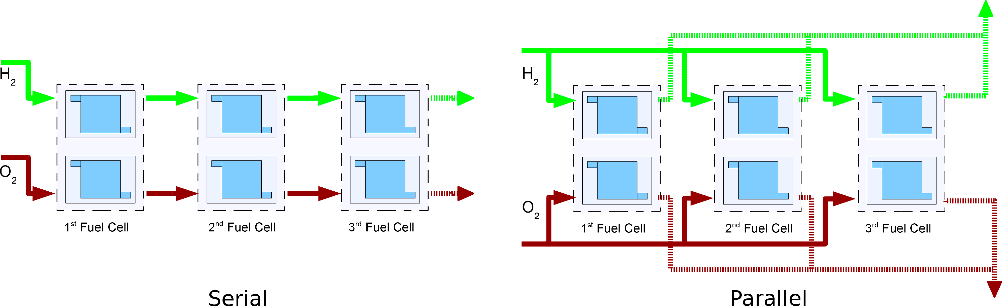
16] (which we call “parallel”), whereas our other solution, “serial”, has not been used in micro fuel cells before. In this case, the fuel flows sequentially from one cell to the next (
Figure 1). The serial topology was introduced by us in a conference paper [
18], but the current design is much smaller, mechanically more robust and less prone to leaks.
Figure 1.
Illustration of serial vs. parallel gas flow topologies: in the case of serial flow, the reactant gases pass from one cell to the next, while in the case of parallel flow, all of the cells are supplied simultaneously.
Figure 1.
Illustration of serial vs. parallel gas flow topologies: in the case of serial flow, the reactant gases pass from one cell to the next, while in the case of parallel flow, all of the cells are supplied simultaneously.
In a previous work [
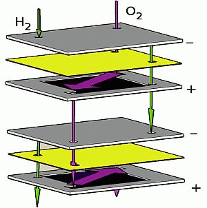
19], we reported on a simplified structure of a single-cell silicon micro FC. This simplification was achieved by using a single silicon chip simultaneously as a current collector, gas flow field and gas diffusion layer (GDL). That arrangement makes them also candidates for bipolar plates. In this work, we show that redesigning the fluidic apertures and using rotational symmetry allows for easy stacking of micro FCs. The stackable cells are identical, but rotated by 180 degrees with respect to each other. A two-cell stack produces 1.6 V of open-circuit voltage (OCV), about double the single hydrogen-fueled cell OCV.
3. Results and Discussion
Both serial and parallel flow stacks were characterized.
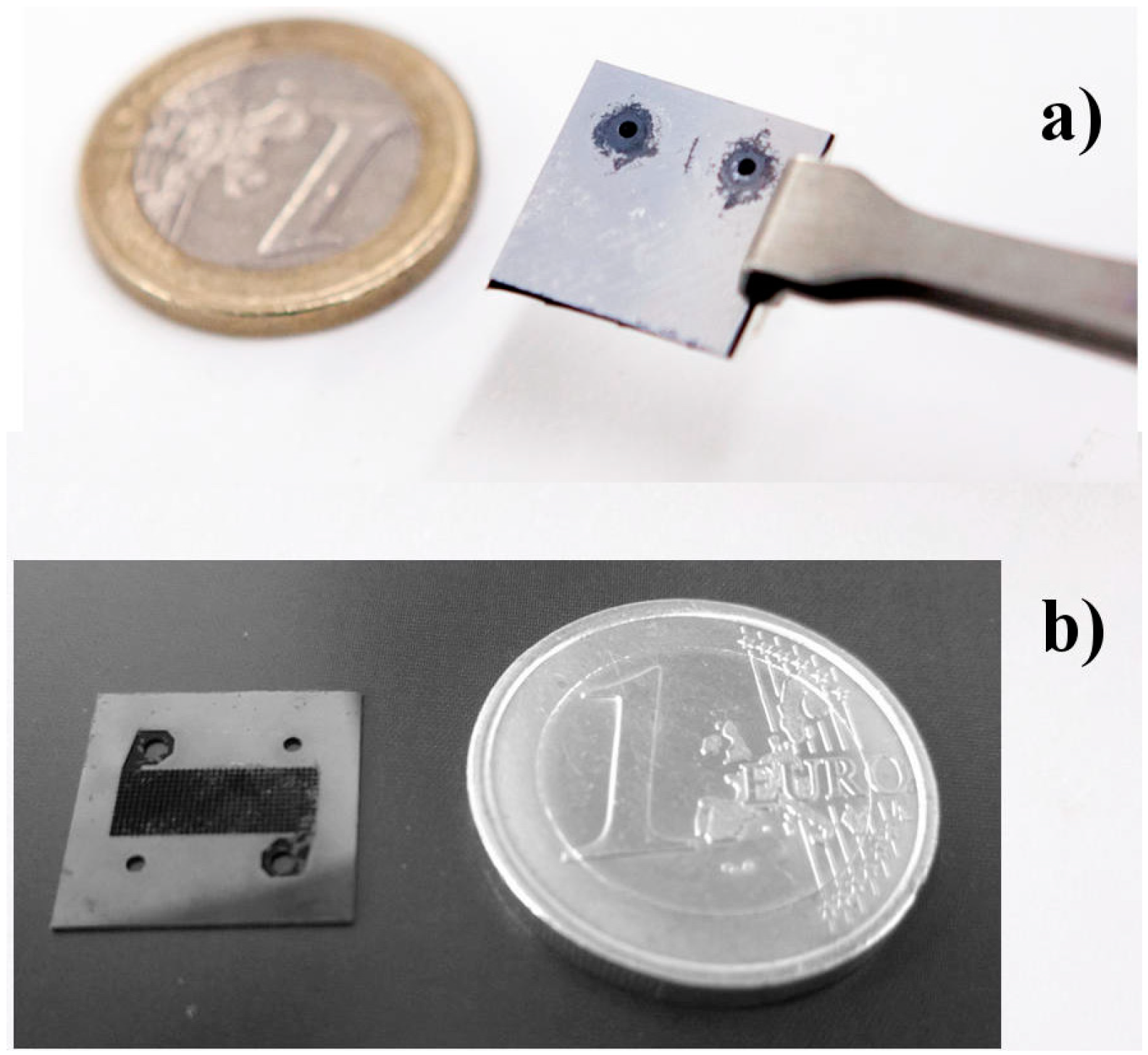
Figure 7 shows post-mortem photographs of a serial flow stack (a) and a parallel flow silicon bipolar plate (b).
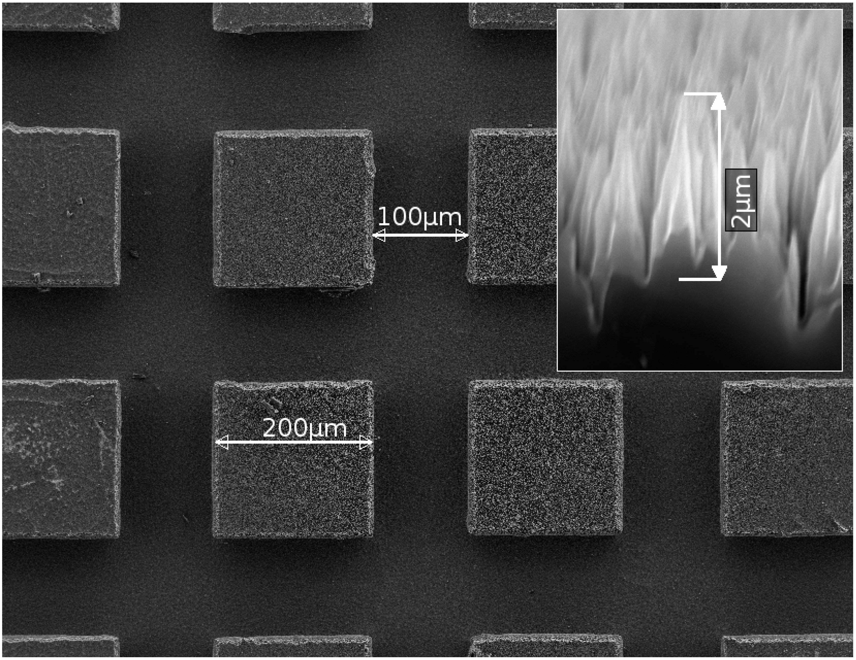
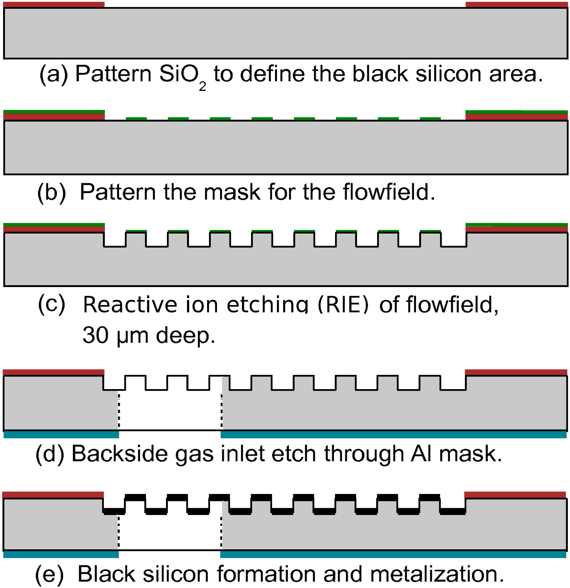
As was mentioned, the last step in fabricating a flow field body is deposition of a thin layer of chromium or platinum on the black silicon GDL. The function of this metal layer is to protect the black silicon from oxidation, which would deteriorate the performance of the fuel cell. The thin metal layer additionally reduces the electrical resistance of the GDL. Measurements on single cells [
19] have demonstrated no difference in performance whether using chromium or platinum for metallization, hence chromium, as the cheaper material, has been chosen for the stackable fuel cell metallization. Even though chromium develops a thin oxide layer when exposed to air, this oxide is electron-conductive, and therefore, the metallization is suitable for our purposes.
Figure 7.
Photograph of a serial flow stack (a) and a parallel flow silicon bipolar plate (b) removed from a stack. Both photographs were taken after characterization. The 1 EUR coin is for size comparison.
Figure 7.
Photograph of a serial flow stack (a) and a parallel flow silicon bipolar plate (b) removed from a stack. Both photographs were taken after characterization. The 1 EUR coin is for size comparison.
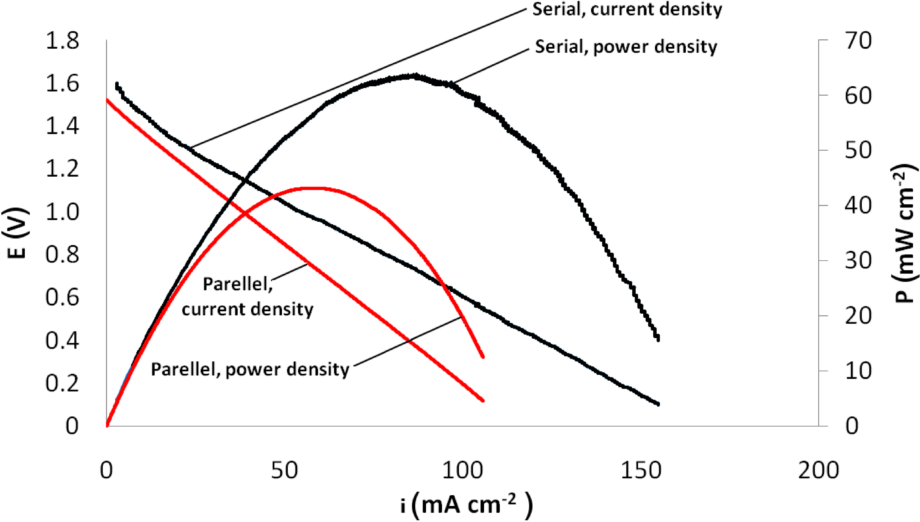
The results of the serial and parallel stacks are summarized with the polarization curves in
Figure 8 and chronoamperometric curves in
Figure 9. As can be seen from the diagrams, the serial flow design produced a higher maximum power density (63 mW·cm
−2 vs. 43 mW·cm
−2) and maximum current density (155 mA·cm
−2 vs. 107 mA·cm
−2) compared to the parallel flow design. The OCV was 1.60 V and 1.52 V for the serial and parallel stacks, respectively, proving their usefulness for increasing the voltage of a micro FC-based power source. The near-doubling of the voltage is obtained because the voltages of the cells are conveniently serialized. The fact that the flow field body voltages end up being in series is what eliminates the need for additional electrical interconnects. This arrangement is trivial with macro fuel cells and batteries, but uncommon with microfabricated fuel cells.
Figure 8.
Polarization curves of two-cell stacks.
Figure 8.
Polarization curves of two-cell stacks.
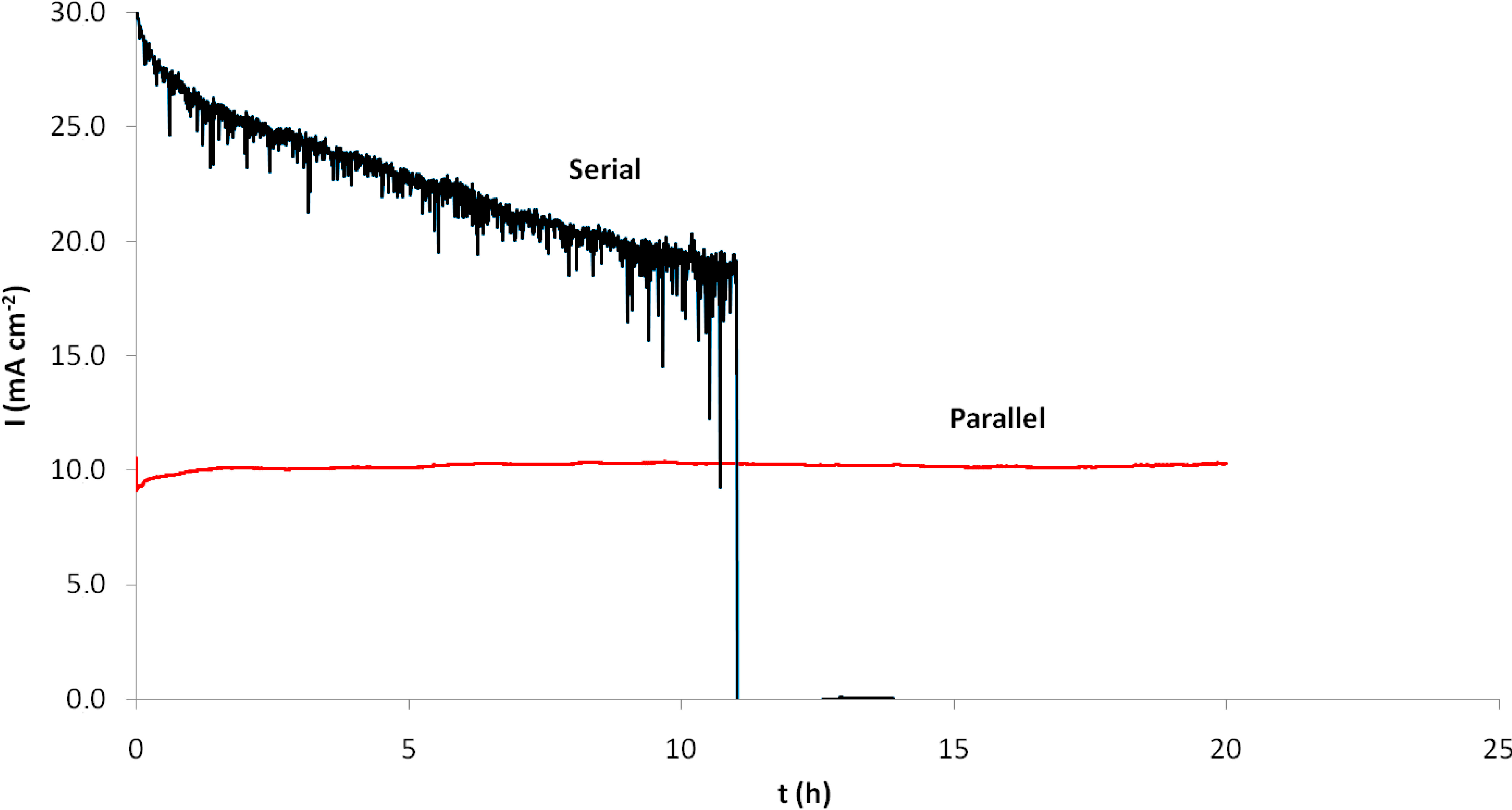
Figure 9.
Chronoamperometric measurements of two-cell stacks.
Figure 9.
Chronoamperometric measurements of two-cell stacks.
While in the case of serial flow, a portion of the gases is depleted when going from one unit cell to the next, this effect is in fact negligible: at a current density of 150 mA·cm−2 and assuming 100% efficiency, with a flow rate of 50 mL·min−1 we have an excess of ~100 times.
Thanks to the large number of data points (about 5000) used in the polarization curve measurements, instability in fuel cell behavior can be easily detected. As can be seen in
Figure 8, the serial flow stack displays slight fluctuations of current when polarized, while the parallel flow stack has a more stable response. The difference is probably due to the fact that in the serial flow design, gases fed to the second cell have flowed through the first cell. The gas is already humid with water formed on the cathode of the first cell, and when more water is formed in the second cell, it may condensate. This could easily obstruct the narrow channels of the flow field. In the parallel design, the gases are fed to both cells directly and run only through one cell. Thus, condensation is less likely to occur. Although a higher rate of gas flow (or stoichiometry) is known to improve water removal from the cell, this effect is not significant at the high stoichiometry of the gases (>5) [
20]. In our case, the flow rate through the unit cell of a serial stack is 50 mL·min
−1 and 25 mL·min
−1 for the parallel stack equivalent to a stoichiometry of several hundred for both gases at chronoamperometric measurement conditions. This indicates that the lower gas flow rate in the parallel stack does not affect the water removal efficiency compared to the serial stack.
The higher performance of the serial flow design can also be explained via the added humidification effect, and it is also visible on the chronoamperometric curves (
Figure 9), obtained by keeping the output voltage stable at 1 V. As can be seen, the parallel design stack produced a smooth and stable result, while with the serial design, the current density was decreasing; there were many transient drops likely due to obstructive water condensate. This condensate gradually accumulates and eventually completely blocks the gas flow in the channels, leading to membrane failure or sealing breakdown at around 11 h. It should be noted that in the serial flow stack, the gas pressures are higher than in the parallel flow stack, so sealing breakdowns are more likely.
One major issue with the silicon micro FC stacks was the fragility of the 300 µm-thick chips. Sealing was not perfect, but increasing the tightening force would cause cracks, which would lead to the failure of the stack. The problem is exacerbated by ripples and bends in the PEM, as the local humidity levels fluctuate, contributing to stresses in the stacked structure. These problems could be mitigated by a smaller active area; a smaller PEM area implies smaller ripples and, hence, smaller stresses in the stack. Improvements in mechanical robustness could be obtained by replacing the Nafion® membranes with acid-loaded porous silicon membranes [
21] or other solid PEMs, which would not deform with changing humidity. Further improvement to the overall mechanical robustness could be also achieved by replacing silicon with other conductive materials, such as aluminum [
22]. The stacking method described in this work would function the same way, irrespective of the materials used for the microfabricated elements, as long as they are electrically conductive. Bonding and sealing of the stack elements should be further improved. One option is to fabricate two adjacent flow fields from the same wafer (flow fields on both sides of the wafer), removing the need for gas sealing between cells. At the same time, this would remove any contact resistance between cells. This would be the exact analogue of bipolar plates used in macro fuel cell stacks.
The stack described in [
16] is analogous to the parallel flow design in this work, with the difference that in [
16], the cells were made of copper. While the measurement conditions between the stack in this work and in [
16] differ (back pressure, use of air instead of O
2 and temperature of the stack), it is evident that the current and power densities obtained are comparable to ours: the authors in [
16] obtained power densities in the range of 40–60 mW·cm
−2 and current densities in the range of 160–220 mA·cm
−2. The authors did not perform chronoamperometric measurements, so the sustained performance of their stack cannot be determined. Since copper is a much more ductile material compared to silicon, it is likely that the stack in [
16] was less fragile and that leaks could be avoided by simply tightening down the stack with sufficient force. Copper is also much more conductive than highly-doped silicon.
4. Conclusions
We have demonstrated a straight-forward method for obtaining vertical micro FC stacks. Our experimental results show that the two-cell stack OCV is 1.60 V, nearly double the single-cell OCV, and the design is amenable to further stacking, due to its inherent simplicity. Both serial and parallel gas flow designs are shown to produce working devices, with 155 mA·cm−2 and 107 mA·cm−2 maximum current densities and 63 mW·cm−2 and 43 mW·cm−2 maximum power densities for the parallel and serial designs, respectively, though the parallel flow design produces more stable results. Our designs permit the free mixing and matching of the serial and parallel flow of fluids, which should be utilized to optimize fuel consumption and current density. It should be noted that the fluidic distribution network is nothing more than simple through-wafer holes, which can be made arbitrarily large and, hence, accommodate any desired flux.
Both serial and parallel flow designs theoretically allow for large numbers of micro FCs stacked on top of each other. If the water management problems could be solved in the case of serial flow, the oxidant and fuel will be depleted after a certain number of cells, which leads to better fuel efficiency, but lower current density. With the parallel flow design, the current density remains the same, but the fuel may not be completely utilized.
The losses in electrical contacts need to be studied and the gas losses reduced by more elaborate bonding and sealing structures. Ways to improve mechanical strength should be also researched. Higher performance and multiple cell stacks are expected to be realized in the future. These devices will have smaller area bipolar plates and membranes to increase the robustness and to achieve greater miniaturization.


