
Structure Design and Implementation of the Passive μ-DMFC

Micro Electro Mechanic System (MEMS) Center, Harbin Institute of Technology, 2A Building Scientific Park, 2 Yikuang Street, Nangang District Harbin, China
*
Author to whom correspondence should be addressed.
†
These authors contributed equally to this work.
Micromachines 2015, 6(2), 230-238; https://doi.org/10.3390/mi6020230
Submission received: 5 November 2014
/
Revised: 20 January 2015
/
Accepted: 29 January 2015
/
Published: 4 February 2015
(This article belongs to the Special Issue Power MEMS)
Abstract
:A dual-chamber anode structure is proposed in order to solve two performance problems of the conventional passive micro direct methanol fuel cell (μ-DMFC). One of the problems is the unstable performance during long time discharge. The second problem is the short operating time. In this structure, low concentration chamber is filled with methanol solution with appropriate concentration for the μ-DMFC. Pure methanol in high concentration chamber diffuses to the low concentration chamber to keep the concentration of methanol solution suitable for long-term discharge of μ-DMFC. In this study, a Nafion-Polytetrafluoroethylene (PTFE) composite membrane is inserted between the two chambers to conduct pure methanol. The experimental results during long-term discharge show that the stable operating time of passive μ-DMFC increases by nearly 2.3 times compared to a conventional one with the same volume. These results could be applied to real products.
1. Introduction
Along with the development of integrated circuit technology and micro electro mechanic system (MEMS) technology, portable digital products have to meet the more integrated and multi-functional requirements. Meanwhile, the requirements raised the qualification for power sources. However, conventional power sources are not satisfying. At this time, a new power source named micro direct methanol fuel cell (μ-DMFC) is proposed in order to meet the requirement. The μ-DMFC has significant advantages in size, weight, energy density, recharge speed and reliability. Therefore, the μ-DMFC is considered as one of the most promising new power sources and attracts a lot of favor and interest of energy industry [1,2,3,4].
In general, the μ-DMFC can operate at room temperature and use low concentration methanol solution as fuel. The principle of the μ-DMFC is shown as the reaction below:
Anode: CH3OH + H2O → 6e− + 6H+ + CO2
Cathode: 3/2O2+ 6e− + 6H+ → 3H2O
Overall: CH3OH + 3/2O2 → 2H2O + CO2
The water is an important reactant according to the reaction [5,6,7]. Conventionally, the μ-DMFC needs peristaltic pump to infuse methanol solution. However, the peristaltic pump consumes much of the energy and makes the system complicated and hard to transport. In contrast to this, passive μ-DMFCs employ a chamber to store the methanol solution and the methanol reaches the anode by convection and diffusion [8,9]. Passive μ-DMFCs have a more compact structure and are easier to package. Thence, passive μ-DMFC has more benefits in practical application and becomes an emphasis of company, research institute and university. Many researchers devote themselves in the improvement of passive μ-DMFC. Mohammad added ionomer content in the catalyst layer of both anode and cathode to improve the performance of passive DMFC [10]. When the ionomer content was 20%, the performance was the best. The performance was proved to be higher than conventional DMFC. Cao utilized mesoporous carbons to optimize the cathode diffusion layer [11]. Experiments showed that the improved diffusion layer could accelerate oxygen transport thus increase the power density and stability. Borghei et al. presented a silicon micro fuel cell to test the durability of μ-DMFC [12]. Carbon nanotubes, carbon nanofibers, and Vulcan were all investigated. Experimental results showed that PtRu-FWNTs provided the best long-term performance. Chen used a nanofiber network catalytic layer in the anode of passive DMFC [13]. In this way, the noble metal PtRu catalyst loading decreased a lot and the performance is even slightly higher. Yuan inserted a porous metal fiber sintered plate between the fuel reservoir and current collector at the anode [14]. The performance is higher than horizontal orientation because the methanol crossover is alleviated. The methods mentioned above make great contribution to optimizing the passive DMFC.
Though the passive μ-DMFCs have been optimized a lot recently, many problems still have to be solved. The μ-DMFC’s anode needs water to be a reactant and transport protons through the proton exchange membrane (PEM). Therefore, large amount of water is needed at the anode to keep the passive μ-DMFC operating normally. Though the most commonly used PEM named Nafion has good proton conductivity and chemical stability, Nafion membrane has obvious methanol crossover. The concentration of the methanol solution is 1 mol·L−1 to 2 mol·L−1, which can prevent the methanol crossover between anode and cathode, and thus increase the performance of the μ-DMFC [15,16]. However, storing lots of water in the liquid storing chamber in anode increases the whole volume of the μ-DMFC system and decreases the energy density. This causes two problems in conventional μ-DMFC. The first problem is the unstable performance during long time discharge and the second is the short operating time. The primary goal of this research is to solve the two problems of conventional μ-DMFC. In this paper, an anode dual-chamber structure μ-DMFC was provided. The anode dual-chamber structure was respectively filled up with low concentration methanol solution and pure methanol solution. The pure methanol solution diffused through the mass transfer blocking layer (MTBL) to the low concentration chamber (LCC). The methanol solution’s concentration in the LCC would not decrease during the operation. A new Nafion-PTFE composite membrane had been proposed to be the MTBL. The investigations showed that compared to conventional μ-DMFC, the stable operating time had been greatly increased.
2. Theory Description
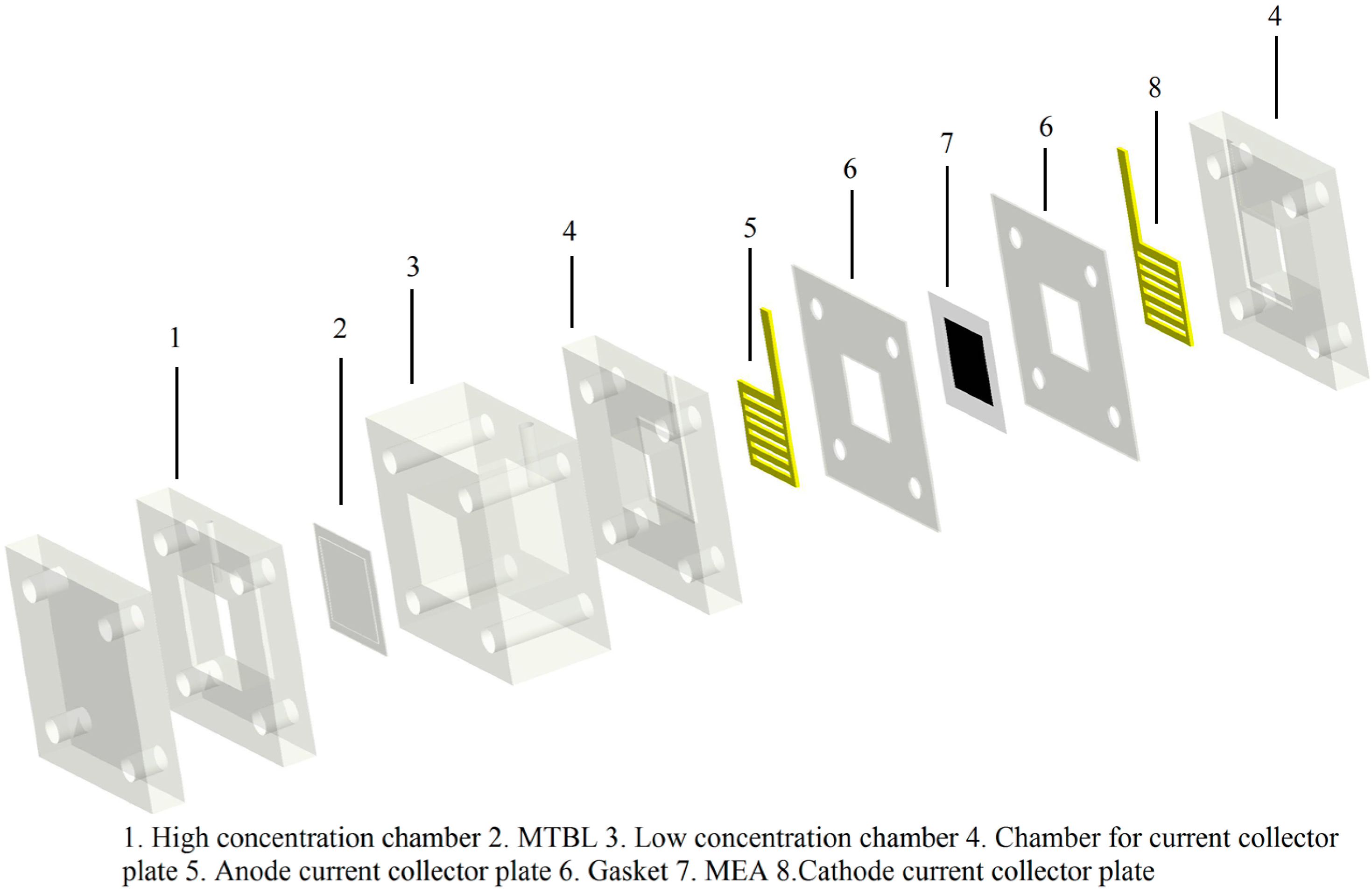
The new structure of the μ-DMFC designed in this research is shown in Figure 1. Pure methanol is stored in the high concentration chamber (HCC) and the methanol solution which is appropriate for the μ-DMFC to operate stably is stored in the LCC. Between the two chambers is a MTBL. This layer should transport pure methanol slowly and prevent water to penetrate. In this way, the water in the LCC will be fully utilized and more pure methanol will participate in the reaction. Methanol crossover between anode and cathode is prevented because the methanol solution’s concentration is suitable in LCC. The methanol’s whole quantity augments and the whole volume of the μ-DMFC stays the same. The energy density increases and the μ-DMFC system is still compact. Thus, the design of the MTBL is very important.
Figure 1.
The structure of the micro direct methanol fuel cell (μ-DMFC) using high concentration methanol solution as fuel.
Figure 1.
The structure of the micro direct methanol fuel cell (μ-DMFC) using high concentration methanol solution as fuel.

The material of MTBL has special requirements. The MTBL should be extremely hydrophobic and methanol-repellent, slowly methanol transported, thin, corrosion-resistant, stable and low cost. Currently, the most popular membrane materials in the μ-DMFC are Nafion and PTFE. The study’s experiments showed that neither of them was the right MTBL. Though PTFE is strongly hydrophobic and methanol-repellent, PTFE membrane does not conduct methanol. Despite of conducting methanol efficiently, Nafion suffers strong methanol crossover and is not hydrophobic and methanol-repellent.
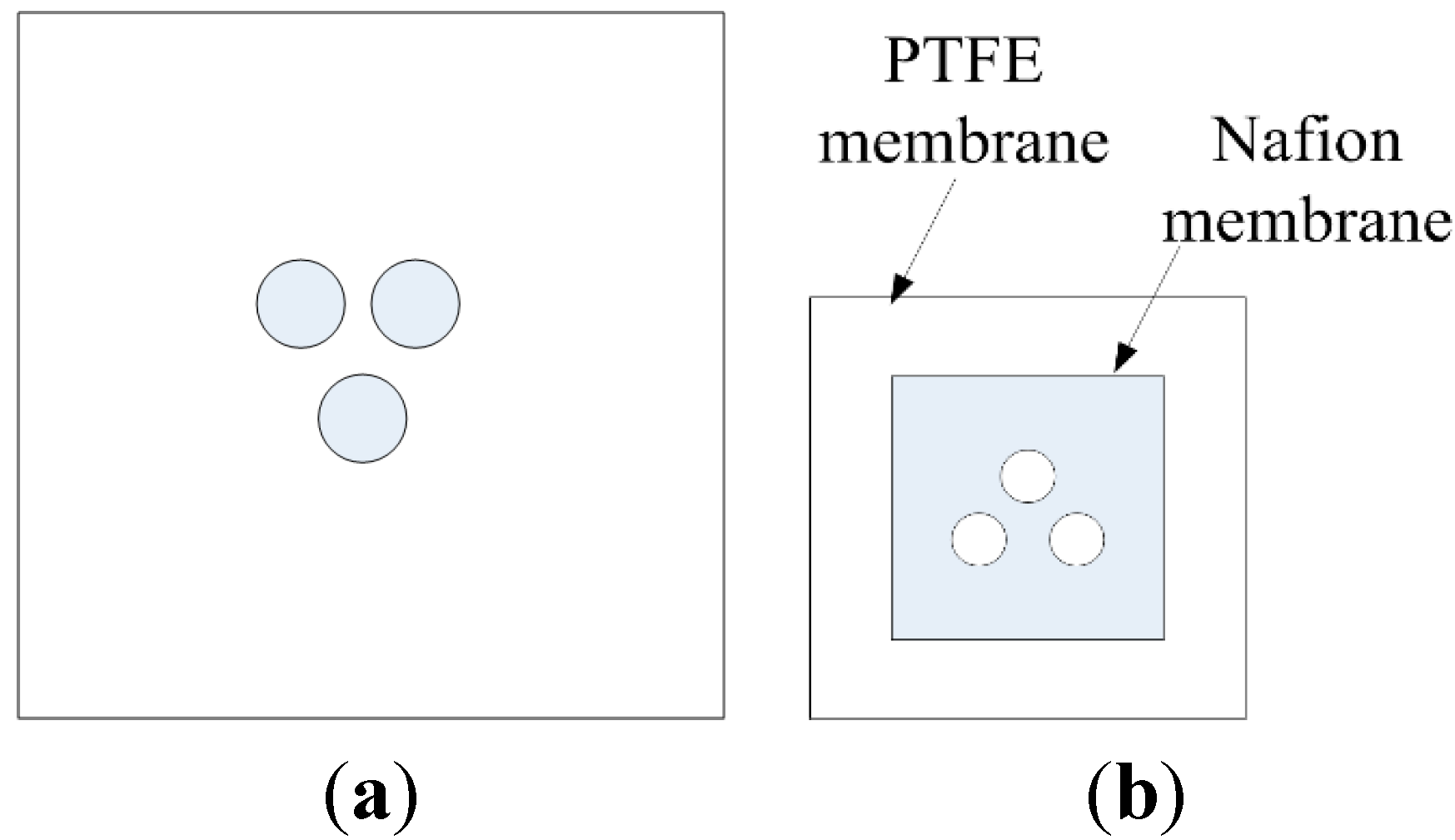
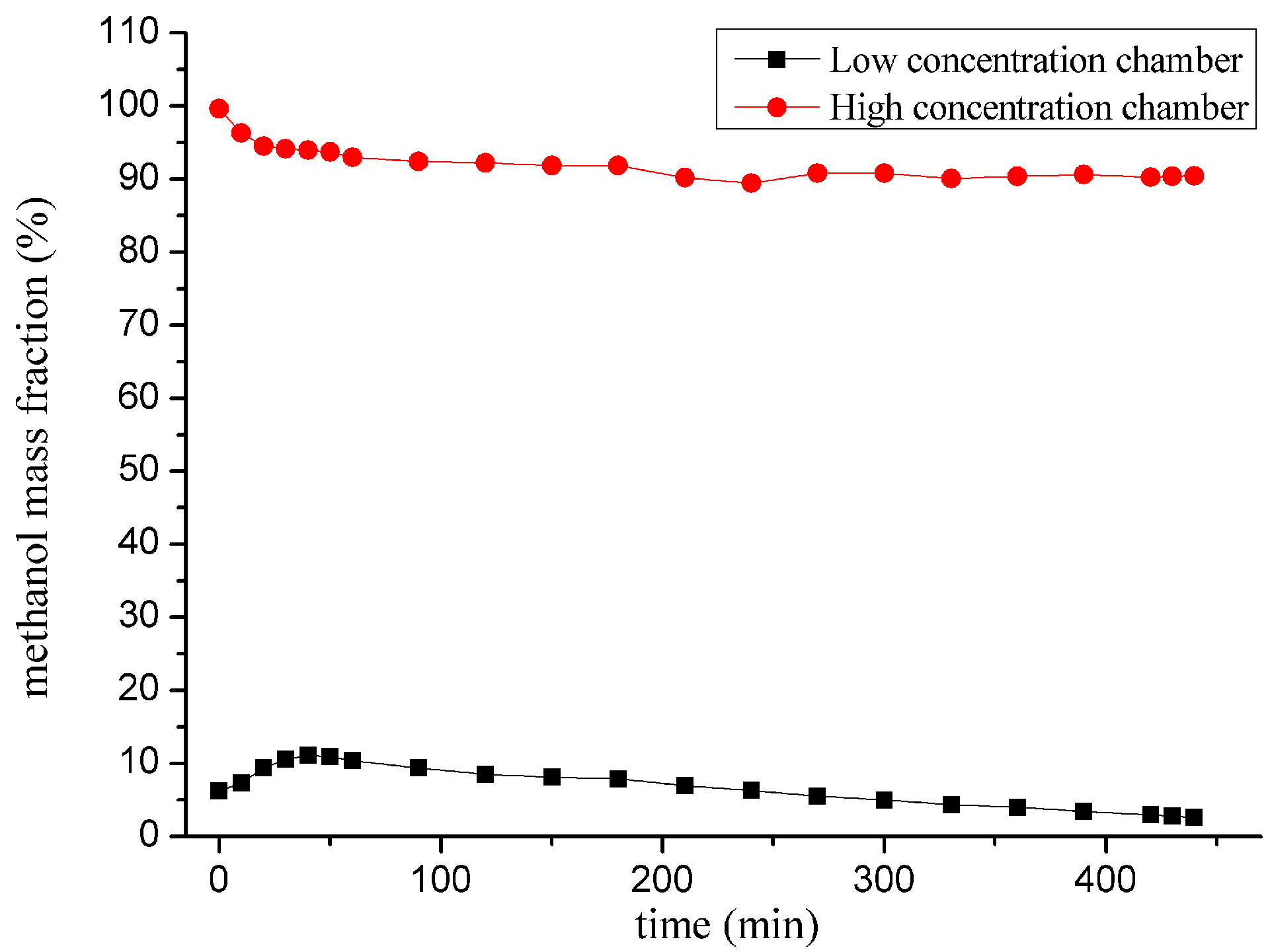
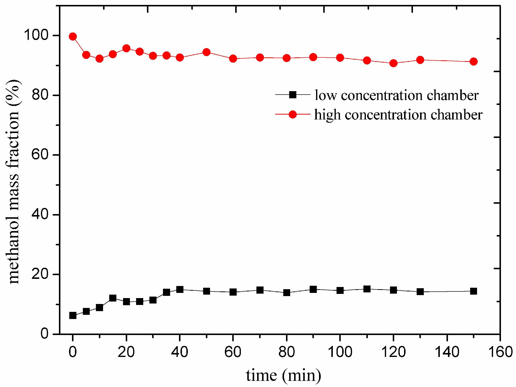
PTFE membrane is hydrophobic, stable and corrosion-resistant. Consequently, a Nafion and PTFE composite membrane had been proposed. PTFE membrane is surface treated to enhance the conductivity. Figure 2a shows the structure of the surface treated PTFE membrane. The round holes’ diameters were 30 μm. A Nafion membrane is attached to this PTFE membrane to slow down the diffusive velocity. Figure 2b shows the Nafion-PTFE composite membrane structure of the MTBL. The design of the composite membrane structure is based on the concentration of methanol solution in LCC. The suitable concentration of the methanol solution is 1 mol·L−1 to 2 mol·L−1 (about 3 wt % to 6 wt %) according to Lu and Ge [15,16]. Previous experimental results of this composite membrane structure are shown in Figure 3. The methanol mass fraction reveals that this composite membrane structure can keep the concentration of the methanol solution in LCC in the appropriate range in long-term discharge. The Nafion membrane side faces the HCC and the PTFE membrane side faces the LCC. PTFE is hydrophobic and methanol-repellent. The water and methanol in LCC will not flow back to LCC through PTFE. The Nafion membrane seems to be easily metamorphosed in pure methanol during early experiments. The penetrative pressure makes Nafion form an arc into the LCC. The methanol may be easier to diffuse into the LCC and the diffusion resistance of water to flow back to the HCC may increase in this condition. A Nafion and PTFE composite membrane had been tested to validate the supposition above.
Figure 2.
(a) Structures of the surface treated PTFE membranes; (b) structures of the Nafion-PTFE composite membranes.
Figure 2.
(a) Structures of the surface treated PTFE membranes; (b) structures of the Nafion-PTFE composite membranes.

Figure 3.
The methanol mass fraction during long-term discharge at 30 mA.

3. Experimental Section
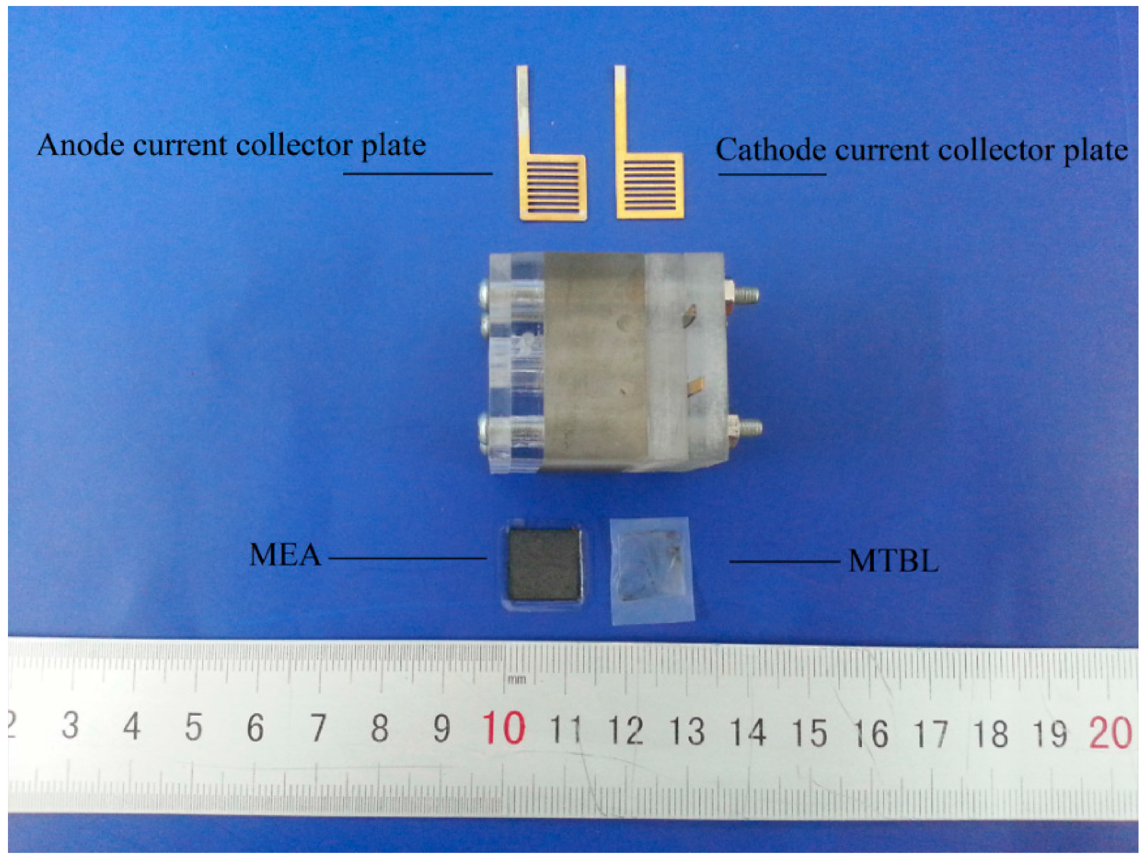
The μ-DMFC’s core size was 1 cm2 and the membrane electrode assembly (MEA) was fabricated by catalyst coated membrane (CCM). CCM process is to load catalyst on the PEM directly. The Nafion 117 membrane was employed as the PEM. Carbon supported catalyst, 40 wt % Pt and 20 wt % Ru, purchased from Johnson Matthey, Inc., was prepared to be the anode catalyst layer. Meanwhile, Carbon supported catalyst, 40 wt % Pt/C, also purchased from Johnson Matthey, Inc. (London, UK), was prepared to be the cathode catalyst layer. Both catalyst layers were loaded on commercial gas diffusion layer (0.2 mm thick non-woven carbon paper purchased from Johnson Matthey, Inc.) and the anode and cathode electrodes were completed. The PEM was sandwiched between the anode and cathode electrodes by hot pressing. The hot press machine’s model was 769YP-15A made by Tianjin scientific instrument corporation (Tianjin, China). Two 0.2 mm thick square 304L stainless steel plates were employed as the anode and cathode current collector plates. The open ratio of anode current collector plate was 45% and the cathode one was 50%. The current collector plates were made by the laser-cut method. Then gold plating was added on the surface of the stainless steel plates to avoid the corrosion phenomenon. The method of gold plating was magnetron sputtering ion plating (MSIP) by JZCK-450 MSIP machine (Shenyang, China) which was manufactured by Shenyang Scientific Instrument Company (Shenyang, China). The thickness of the gold was 200 nm and was enough to provide good conductivity and corrosion resistance. The gaskets were made by the laser-cutter. The gasket’s functions were preventing the leakage of reactant, keeping the anode and cathode from short circuiting and decreasing the assembly clamping force. Also, the material of the gaskets was silica gel. During test, the MEA was sandwiched between the anode and cathode current collector to form the core μ-DMFC. The PTFE was surface treated by precise laser cutter and the three round holes diameters were strictly controlled at 30 μm. Then the Nafion 117 membrane was attached to the PTFE. The Nafion-PTFE composite membrane was placed between the two chambers. The dual chamber anode structure was attached to the core μ-DMFC. The photograph of the whole μ-DMFC designed in this paper is shown in Figure 4.
Figure 4.
Photograph of the whole μ-DMFC designed in this paper.

The methanol solution’s concentration was measured mostly by gas chromatograph. The gas chromatograph’s model is SP-6890 made in Ruihong Chemical Instrument Inc., Shandong, China. The data measured by gas chromatograph is transported to chromatography data workstation made by Zhida information engineering Inc, University of Zhejiang, China. The discharging process of the μ-DMFC designed in this paper was recorded by the electronic loading (ITECH DC electronic load IT8811 by ITECH Electronic CO., LTD., Nanjing, China).
4. Results and Discussion
Figure 5 shows the methanol solution-time curves in the dual-chamber μ-DMFC during experiment. The Nafion-PTFE composite membrane was employed as MTBL. The whole experiment was done at room temperature. During test, the HCC and LCC were respectively filled with 1 mL pure methanol solution and 1 mL 2 mol·L−1 methanol solution. The selection of the methanol solution’s concentration in LCC was made according to Ge and Lu [15,16]. The μ-DMFC was operating at open circuit condition with both chambers’ inlets closed. The experimental results showed that the methanol’s mass fraction in LCC increased from 6% (2 mol·L−1) to 15%. The mass fraction in HCC decreased from 100% to 91%. Though the mass fraction in HCC decreased very fast, it still remained at over 90%. The experimental results reveal that the Nafion-PTFE composite membrane reduced the pure methanol solution diffusion speed from the HCC to LCC. At the same time, the backflow of water from LCC to HCC was reduced.
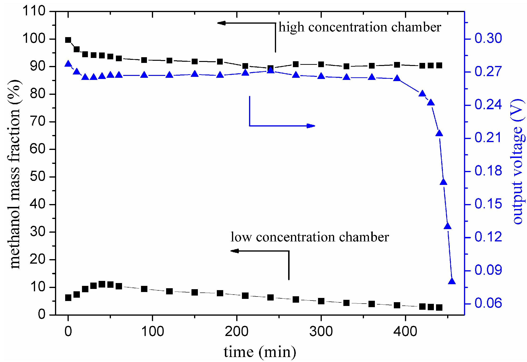
The experimental results of dual-chamber μ-DMFC employed Nafion-PTFE composite membranes as MTBL is shown in Figure 6. The μ-DMFC was operating at 30 mA constant current. Figure 6 displays that the dual-chamber anode μ-DMFC designed in this paper could discharge about 420 min. Then the performance started to decrease. Meanwhile, the μ-DMFC’s concentration polarization happened and the performance was very low. The effective operating time is defined as the time while the voltage is above the 70% of initial voltage in this research. The stable operating time of dual-chamber μ-DMFCs was 440 min under the definition of this research. The mass fraction of methanol solution in HCC did not change very much. This means that the holes did not cause the water to flow back and wasting water. The methanol fraction in LCC remained appropriate for the reaction. Therefore the μ-DMFC was stable while Nafion-PTFE composite membrane was introduced as MTBL.
Figure 5.
Methanol solution-time curves in the dual-chamber μ-DMFC.

Figure 6.
Stability tests of the μ-DMFC operating at 30 mA.

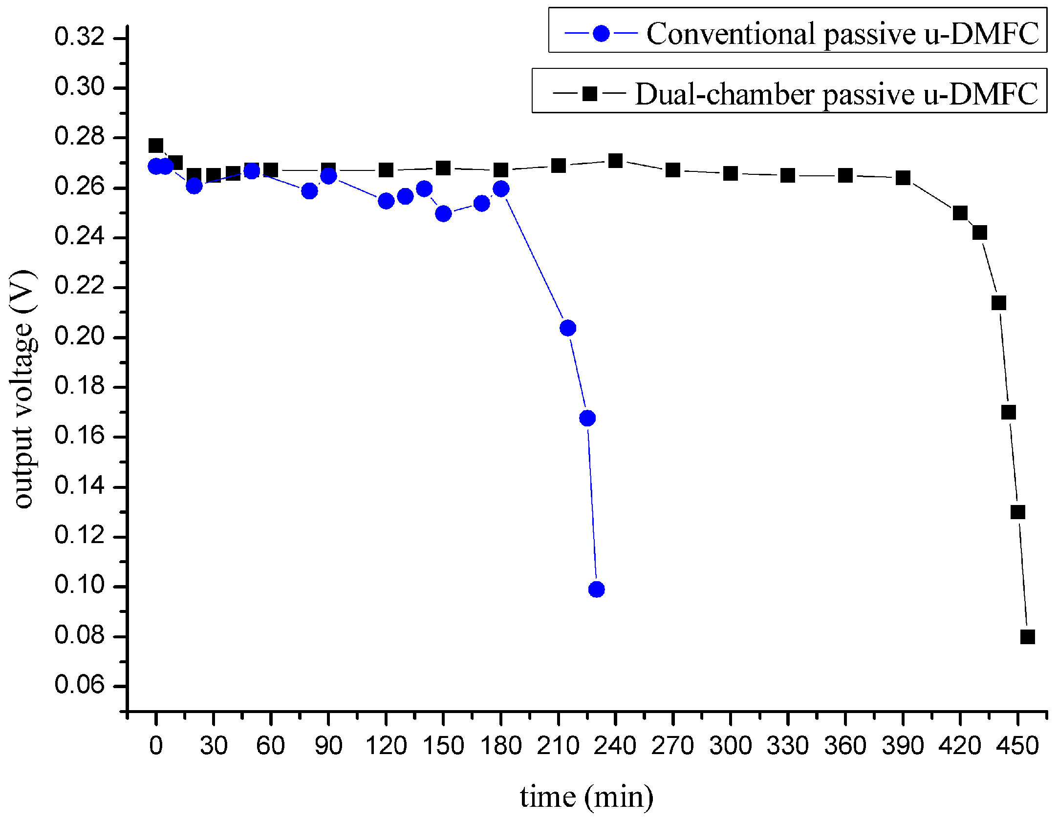
The performance of conventional passive μ-DMFC with the same volume as the dual-chamber μ-DMFC was also tested to validate the supposition in Section 2. The conventional passive μ-DMFC was feed with 2 mol·L−1 methanol solution and the μ-DMFC was operating at 30 mA constant current. The selection of concentration also depended on Ge and Lu [15,16]. The contrastive result of dual-chamber passive μ-DMFC and conventional passive μ-DMFC was shown in Figure 7. The stable operating time of conventional passive μ-DMFC was 190 min. Compared to conventional anode structure, the stable operating time of the μ-DMFC using dual-chamber anode structure is increased by nearly 2.3 times. This phenomenon indicates that the pure methanol solution in HCC supplied into LCC thus increasing the operation time. With the experimental results above, the supposition in Section 2 is validated.
Figure 7.
Methanol’s mass fraction and the operating time of conventional passive μ-DMFC fed with 2mol/L methanol solution.
Figure 7.
Methanol’s mass fraction and the operating time of conventional passive μ-DMFC fed with 2mol/L methanol solution.

On the basis of the experimental results, these conclusions can be educed. Nafion-PTFE composite membranes could meet the demand of MTBL. Nafion-PTFE composite membrane makes methanol diffuse into the LCC more easily and increases the diffusion resistance of water to flow back to the HCC. The dual-chamber anode structure could extend the operating time and keep the methanol solution’s concentration in LCC from increasing. In this method, the μ-DMFC’s performance during long time discharge is more stable and the operating time is longer. The energy density of the μ-DMFC increased. However, the methanol of HCC stops supplying into the LCC while the methanol in HCC is not exhausted. This phenomenon is probably caused by the low liquid level in LCC. The liquid level falls below the holes of MTBL after 400 min. In this term, the methanol can not supply to the methanol solution. The concentration of methanol in LCC is not suitable for the μ-DMFC. Meanwhile, the output voltage is degraded.
5. Conclusions
In conclusion, a dual-chamber anode μ-DMFC structure is presented in order to make the μ-DMFC’s performance stable and lengthen the operating time. Compared with the researcher’s study on conventional passive μ-DMFC under the same condition, the operating time increases by nearly 2.3 times. A Nafion-PTFE composite membrane is proposed to meet the demand of MTBL. These results can be applied to real products. Though many experiments have been done, some problems still need to be further investigated. For instance, the methanol solution in the HCC is not exhausted, and so on. After some deep investigation, these problems will also be solved.
Acknowledgments
The work described in this paper was supported by the National Natural Science Funds of China (No. 61176113), a grant from the Programs Foundation of the Ministry of Education of China (No. 20102302110026).
Author Contributions
Xiaowei Liu provided the devices and platform for the experiments. Shuo Fang processed the experiments and wrote most parts of the manuscript. Zezhong Ma participated in the experiments and checked the manuscript. Yufeng Zhang presented the designing of the fuel cell and decided the framework of the whole article.
Conflicts of Interest
The authors declare no conflict of interest.
References
- Wu, Q.X.; Zhao, T.S.; Chen, R.; Yang, W.W. Effects of anode microporous layers made of carbon powder and nanotubes on water transport in direct methanol fuel cells. J. Power Sources 2009, 191, 304–311. [Google Scholar]
- Chang, I.; Ha, S.; Kim, J.; Lee, J.; Cha, S.W. Performance evaluation of passive direct methanol fuel cell with methanol vapour supplied through a flow channel. J. Power Sources 2008, 184, 9–15. [Google Scholar]
- Liu, Y.; Xie, X.; Shang, Y.; Li, R.; Qi, L.; Guo, J.; Mathur, V.K. Power characteristics and fluid transfer in 40W direct methanol fuel cell stack. J. Power Sources 2007, 164, 322–327. [Google Scholar] [CrossRef]
- Achmad, F.; Kamarudin, S.K.; Daud, W.R.W.; Majlan, E.H. Passive direct methanol fuel cells for portable electronic devices. Appl. Energy 2011, 88, 1681–1689. [Google Scholar] [CrossRef]
- Oliveira, V.B.; Rangel, C.M.; Pinto, A.M.F.R. Water management in direct methanol fuel cells. Int. J. Hydrog. Energy 2009, 34, 8245–8256. [Google Scholar] [CrossRef]
- Zhang, B.; Zhang, Y.; He, H.; Li, J.; Yuan, Z.; Na, C.; Liu, X. Development and performance analysis of a metallic micro-direct methanol fuel cell for high-performance applications. J. Power Sources 2010, 195, 7338–7348. [Google Scholar] [CrossRef]
- Zhang, Y.; Zhang, P.; Yuan, Z.; He, H.; Zhao, Y.; Liu, X. A tapered serpentine flow field for the anode of micro direct methanol fuel cells. J. Power Sources 2011, 196, 3255–3259. [Google Scholar] [CrossRef]
- Chen, C.Y.; Shiu, J.Y.; Lee, Y.S. Development of a small DMFC bipolar plate stack for portable applications. J. Power Sources 2006, 159, 1042–1047. [Google Scholar] [CrossRef]
- Kamaruddin, M.Z.F.; Kamarudin, S.K.; Daud, W.R.W.; Masdar, M.S. An overview of fuel management in direct methanol fuel cells. Renew. Sustain. Energy Rev. 2013, 24, 557–565. [Google Scholar] [CrossRef]
- Abdelkareem, M.A.; Tsujiguchi, T.; Nakagawa, N. Effect of black catalyst ionomer content on the performance of passive DMFC. J. Power Sources 2010, 195, 6287–6293. [Google Scholar] [CrossRef]
- Cao, J.; Wang, L.; Song, L.; Xu, J.; Wang, H.; Chen, Z.; Huang, Q.; Yang, H. Novel cathodal diffusion layer with mesoporous carbon for the passive direct methanol fuel cell. Electrochimica Acta 2014, 118, 163–168. [Google Scholar] [CrossRef]
- Borghei, M.; Scotti, G.; Kanninen, P.; Weckman, T.; Anoshkin, I.V.; Nasibulin, A.G.; Franssila, S.; Kauppinen, E.I.; Kallio, T.; Ruiz, V. Enhanced performance of a silicon microfabricated direct methanol fuel cell with PtRu catalysts supported on few-walled carbon nanotubes. Energy 2014, 65, 612–620. [Google Scholar] [CrossRef]
- Chen, P.; Wu, H.; Yuan, T.; Zou, Z.; Zhang, H.; Zheng, J.; Yang, H. Electronspun nanofiber network anode for a passive direct methanol fuel cell. J. Power Sources 2014, 255, 70–75. [Google Scholar] [CrossRef]
- Yuan, W.; Deng, J.; Zhang, Z.; Yang, X.; Tang, Y. Study on operational aspects of a passive direct methanol fuel cell incorporating an anodic methanol barrier. Renew. Energy 2014, 62, 640–648. [Google Scholar] [CrossRef]
- Lu, G.Q.; Wang, C.Y. Development of micro direct methanol fuel cells for high power applications. J. Power Sources 2005, 144, 141–145. [Google Scholar] [CrossRef]
- Ge, J.; Liu, H. Experimental studies of a direct methanol fuel cell. J. Power Sources 2005, 142, 56–69. [Google Scholar] [CrossRef]
© 2015 by the authors; licensee MDPI, Basel, Switzerland. This article is an open access article distributed under the terms and conditions of the Creative Commons Attribution license (http://creativecommons.org/licenses/by/4.0/).
Share and Cite
MDPI and ACS Style
Liu, X.; Fang, S.; Ma, Z.; Zhang, Y. Structure Design and Implementation of the Passive μ-DMFC. Micromachines 2015, 6, 230-238. https://doi.org/10.3390/mi6020230
AMA Style
Liu X, Fang S, Ma Z, Zhang Y. Structure Design and Implementation of the Passive μ-DMFC. Micromachines. 2015; 6(2):230-238. https://doi.org/10.3390/mi6020230
Chicago/Turabian StyleLiu, Xiaowei, Shuo Fang, Zezhong Ma, and Yufeng Zhang. 2015. "Structure Design and Implementation of the Passive μ-DMFC" Micromachines 6, no. 2: 230-238. https://doi.org/10.3390/mi6020230