Article

A Nonlinear Suspended Energy Harvester for a Tire Pressure Monitoring System

1
Department of Mechanical and Electromechanical Engineering, National Sun Yat-sen University, No. 70 Lienhai Road, Kaohsiung 80424, Taiwan
2
Department of Aerospace and Systems Engineering, Feng Chia University, No. 100 Wenhwa Road, Seatwen, Taichung 40724, Taiwan
3
Department of Mechanical and Computer-Aided Engineering, National Formosa University, Yunlin 632, Taiwan
*
Author to whom correspondence should be addressed.
Micromachines 2015, 6(3), 312-327; https://doi.org/10.3390/mi6030312
Submission received: 31 December 2014 / Revised: 17 February 2015 / Accepted: 24 February 2015 / Published: 27 February 2015
(This article belongs to the Special Issue Power MEMS)

Abstract

:
The objective of this study is to develop and analyze a nonlinear suspended energy harvester (NSEH) that can be mounted on a rotating wheel. The device comprises a permanent magnet as a mass in the kinetic system, two springs, and two coil sets. The mass vibrates along the transverse direction because of the variations in gravitational force. This research establishes nonlinear vibration equations based on the resonance frequency variation of the energy harvester; these equations are used for analyzing the power generation and vibration of the harvester. The kinetic behaviors can be determined according to the stiffness in the two directions of the two suspended springs. Electromagnetic damping is examined to estimate the power output and effect of the kinematic behaviors on NSEH. The power output of the NSEH with a 52 Ω resistor connected in series ranged from approximately 30 to 4200 μW at wheel speeds that ranged from nearly 200 to 900 rpm.

1. Introduction

The increasing demand for embedding a tire pressure measurement system (TPMS) in wheels as a car safety device has drawn considerable research attention. A TPMS is an electronic safety system designed for monitoring the air pressure inside pneumatic tires on automobiles and other vehicles. However, the power supply of the pressure sensor of a TPMS still relies on batteries, which exhibit several drawbacks such as low durability, difficulty of replacement, and most notably, inferior sustainability in terms of environmental impact. An alternative approach for replacing the battery in a TPMS involves harvesting vibration energy from the environment [1,2,3,4]. Energy harvesters are devices that transform ambient energy, such as kinetic, heat, light, and acoustic energy, into electric energy. Kinetic energy harvesters are ideal power sources for TPMSs because the wheels of cars roll on roads.
Kinetic energy harvesting is often conducted using electromagnetic [5,6,7] and piezoelectric harvesting devices [8,9,10,11,12,13], and micro-scale energy harvesters composed of different materials have been presented by researchers [14,15]. The number of studies on harvesting energy from the environment for TPMSs has increased in recent years. The rotating speed of a wheel varies with the speed of the car, determined by the driver. This means that the efficiencies of energy harvesters for TPMSs should be considered at different wheel speeds. Common linear kinetic (mass-spring-damper) systems, which have a narrow frequency range, are poorly suited for energy harvesters in TPMSs. This is because the output power of a linear harvester drops dramatically under off-resonance conditions [16]. This problem can be overcome by using nonlinear mechanisms, such as nonlinear springs [17,18,19], nonlinear oscillators [20], frequency tunable mechanisms [21,22,23,24], and multi-frequency harvesters [25,26]. The number of studies conducted on nonlinear energy harvesters as power sources for the pressure sensors in TPMSs has increased in recent years. An electromagnetic energy harvester [27] mounted on the inner tire generated sufficient power to transmit tire sensor data multiple times per minute. Xuan et al. [28] proposed a seesaw-structured energy harvester for TPMSs; the proposed harvester can effectively overcome the effect of high centrifugal forces and was tested using an average power of 5.625 μW at 750 rpm. In [29], a piezofiber energy harvester was developed and mounted inside the tire to provide 34.5 μJ for one wheel cycle. Wang et al. [30,31,32] developed pendulum-based energy harvesters for harvesting the kinetic energy from a rotating wheel. The generated power ranged from 300 to 400 μW at wheel speeds between 300 and 500 rpm. A high centrifugal force was exerted on the device mounted on the wheel, especially at high wheel rotation speeds. When the kinematic pair of the energy harvester mounted on the wheel functions as the rotary union, friction force, which is caused by the high centrifugal force and results in kinetic energy loss, cannot be avoided [33].
This study proposes a novel nonlinear suspended energy harvester (NSEH), which is embedded in a rotating wheel, for a TPMS. The device comprises a permanent magnet as a mass, two suspended springs, and two coil sets for converting kinetic energy to electric energy. The NSEH demonstrates nonlinear kinetic behaviors because of the centrifugal and gravitational force as well as the stiffness of the two suspended springs. The rest of this paper is organized as follows. The “Overall design of the NSEH” section focuses on the design concept of the NSEH and derivation of its kinetic equations. The dynamic behaviors of the NSEH, including the transient response observed using analytical models and finite element software, as well as a spectrum analysis are described. The magnetic field strength analysis used for calculating the electromotive force (EMF) is presented in the “Output voltage and electromagnetic damping” section. In the “Experimental results” section, the prototype of the NSEH, experimental setups, and power generation results are presented. Finally, the conclusions are provided in the “Conclusions” section.

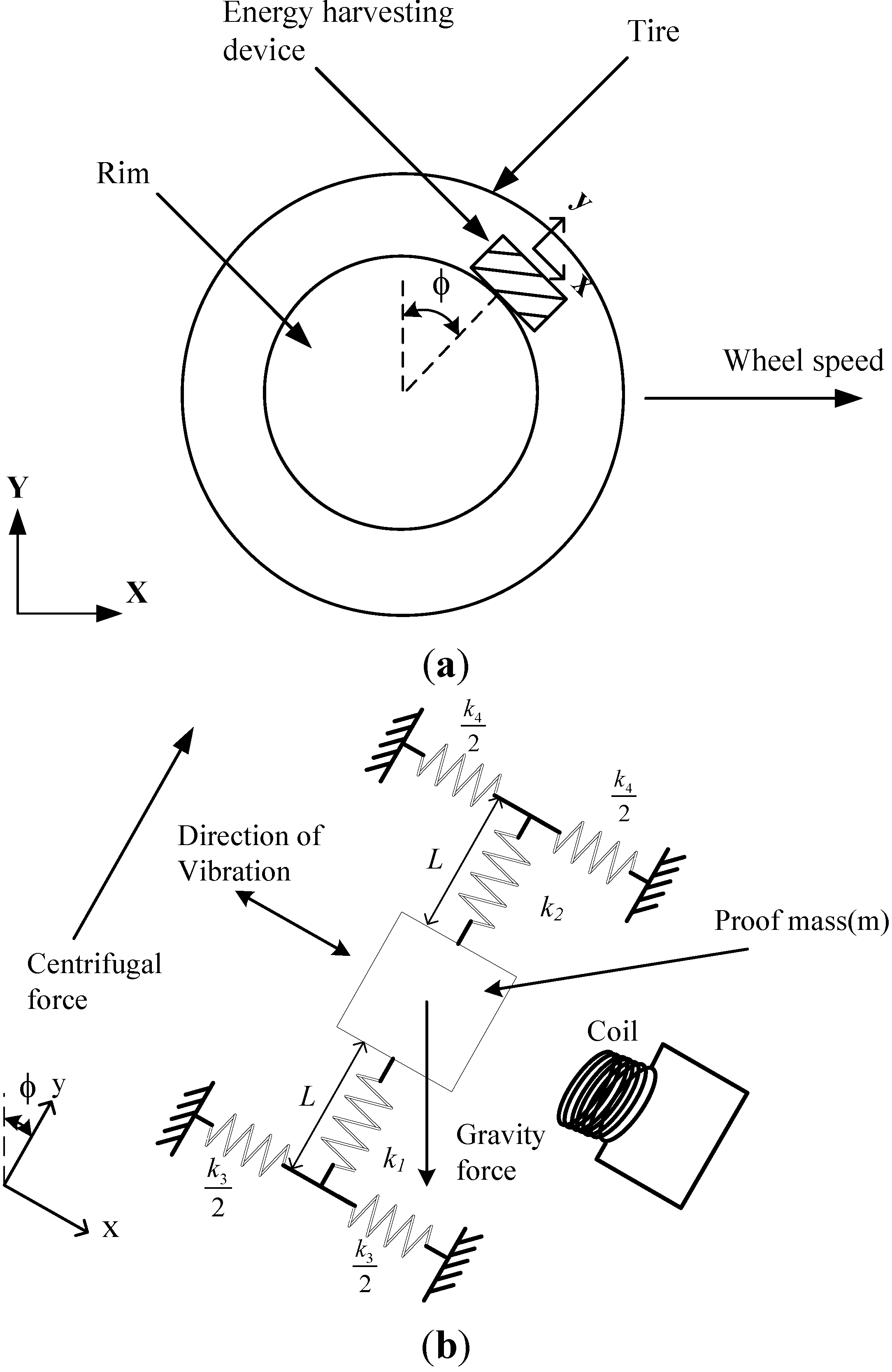
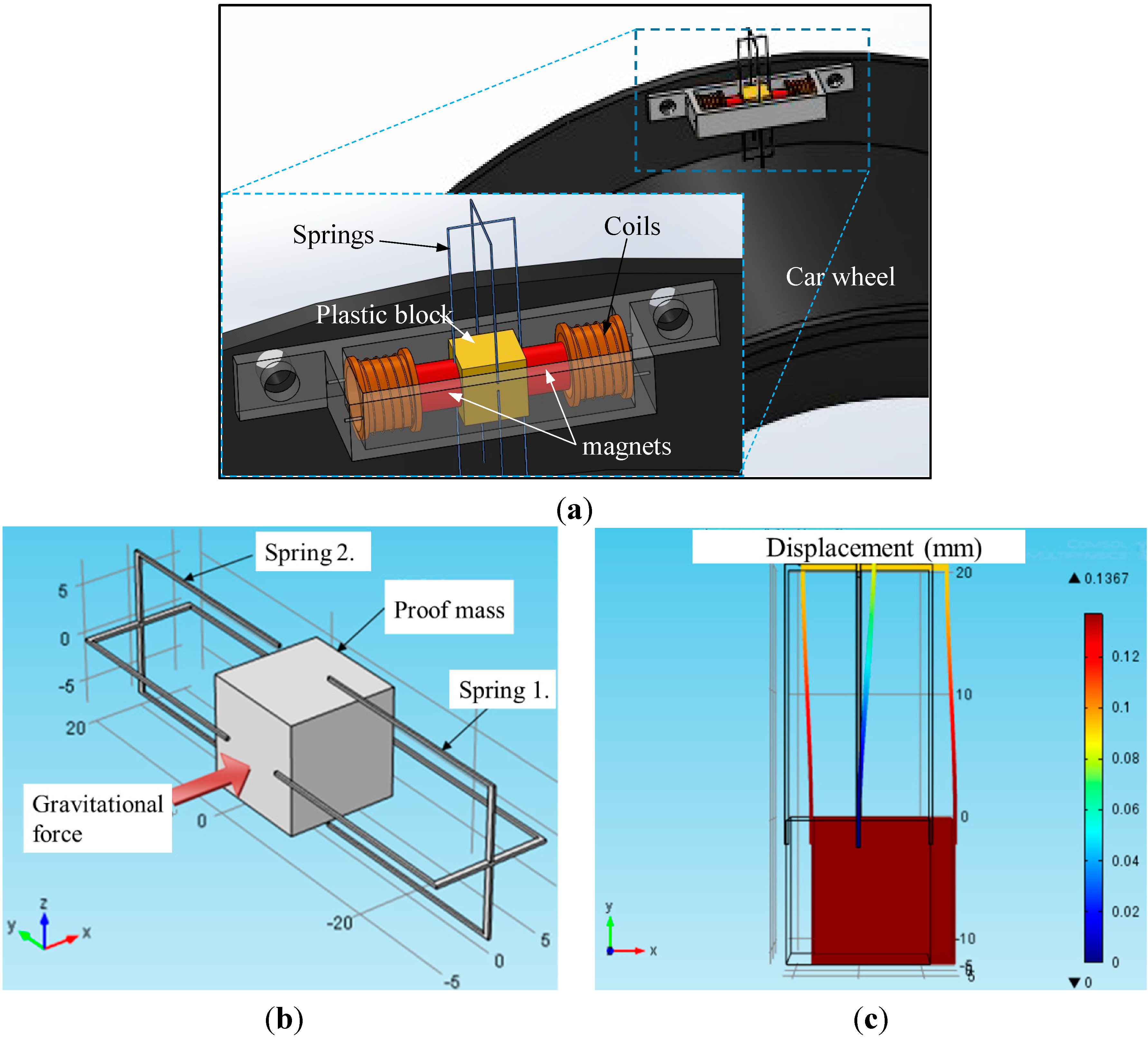
2. Overall Design of the NSEH

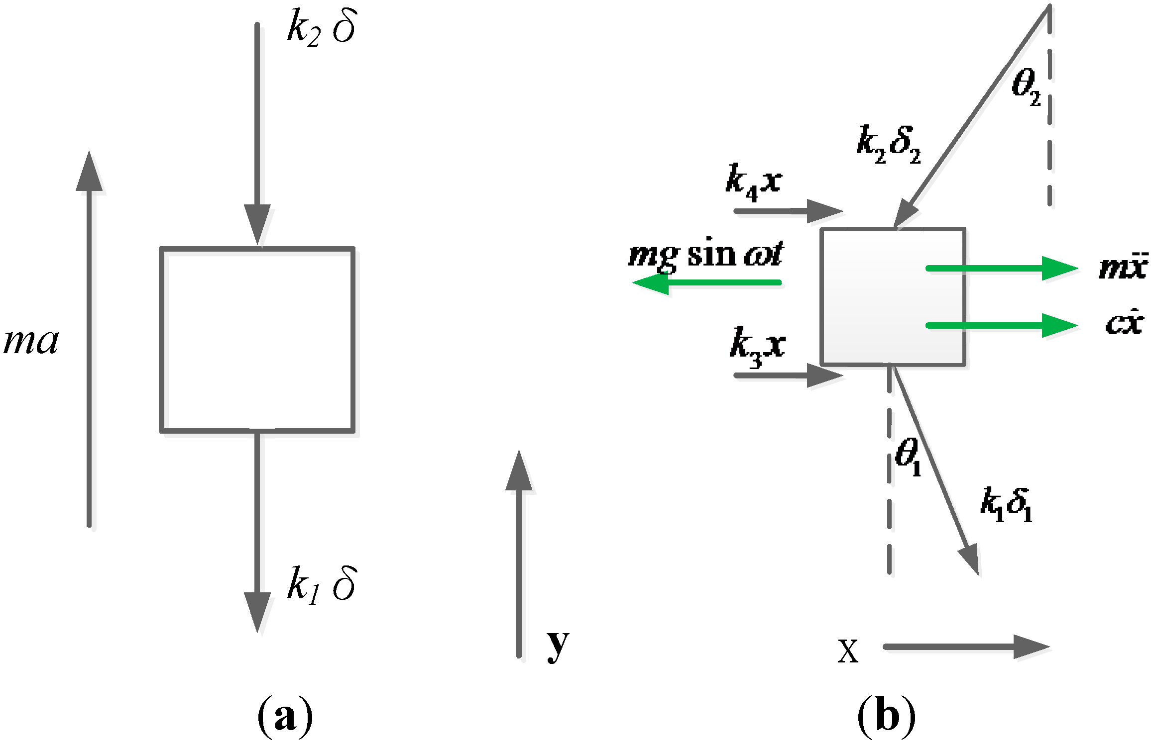
2.1. Kinetic Equations

Figure 1a shows an energy harvester embedded in a progressive car wheel. The device is mounted on the rim. Figure 1b illustrates the detailed configuration of the device. The device structure consists of a proof mass suspended from two springs with bidirectional stiffness and two coil sets. The proof mass could be a magnet that induces a current in the coil for converting the dynamic energy into electrical energy. The device is orientated such that the centrifugal force is along the longitudinal direction (i.e., the y axis). The angle ϕ changes as the wheel rotates (i.e., ϕ = ωt, where ω is the angular velocity of the wheel, and t is the time). This induces the transverse component of gravity to change when the wheel rotates. Because of the variation in gravity, the proof mass vibrates along the transverse direction.
Figure 1. NSEH (nonlinear suspended energy harvester) embedded in a rotating wheel. (a) Schematic diagram of a rolling wheel. (b) Diagram of the NSEH.
Micromachines 06 00312 g001
The spring is relaxed when the wheel is at rest. When the wheel rotates at an angular velocity ω, the centrifugal acceleration is a n = ω 2 r , where r is the distance between the wheel center and proof mass. The centrifugal acceleration is along the longitudinal direction of the spring-mass system. The gravity is considerably lower than the centrifugal acceleration; therefore, the gravity has no effect on the longitudinal displacement δ. Figure 2a shows a free-body diagram of the spring-mass system. The longitudinal displacement δ can be rewritten as follows:
δ = m a k 1 + k 2
where k1 and k2 represent the spring constants of the two springs along the longitudinal direction. If the mass is subjected to transverse excitation m·g·sinωt induced by gravity, then the mass undergoes transverse displacement x (Figure 2b). The components x of the restoring force caused by the two springs can be calculated as follows:
k 1 · δ 1 · sin θ 1 + k 3 · x k 2 · δ 2 · sin θ 2 + k 4 · x
where δ 1 = [ x 2 + ( L + δ ) 2 L ] , sin θ 1 = x x 2 + ( L + δ ) 2 , δ 2 = [ L x 2 + ( L δ ) 2 ] , sin θ 2 = x x 2 + ( L δ ) 2 and k3 and k4 represent the spring constants of the two springs along the transverse direction. The spring constants k1 and k3 are defined for the spring 1 connected with the downside surface of the magnet. k2 and k4 are defined for the spring 2 connected with the upside surface of the magnet. Furthermore, L is the free length of the two springs. The centrifugal force of an NSEH mounted on a rotating wheel is constant at constant car speeds. Therefore, this study did not consider harvesting the kinetic energy in the radial direction. Because centrifugal and gravitational force act through the mass center of the proof mass, and the two springs are symmetrical, this study neglected the rotation motion of the proof mass. Some elementary trigonometric analyses were performed, and the dynamic equation of the proof mass according the local x-y coordinates can be expressed as follows:
m x ¨ + c x ˙ + f ( x ) = m · g · sin ( ω · t )
where c is the total damping; c = ce + cm, in which ce and cm are the electromagnetic damping and material damping, respectively.
Figure 2. Kinetic body diagram. (a) y-axis and (b) x-axis.
Micromachines 06 00312 g002
The electromagnetic damping calculates the coupling effect between the generated current and the motion of the magnet. The function f(x) is thus:
f ( x ) = x [ k 1 ( 1 L x 2 + ( L + δ ) 2 ) + k 2 ( 1 L x 2 + ( L δ ) 2 ) + k 3 + k 4 ]
Equation (3) is a nonlinear differential equation and can be solved through a numerical method. If the transverse displacement x is small compared with L, then Equation (4) can be reduced to:
f ( x ) = [ k 1 ( 1 L L + δ ) + k 2 ( 1 L L δ ) + k 3 + k 4 ] x
Substituting Equation (5) into Equation (3) provides a vibration equation at a constant car speed:
m x ¨ + c x ˙ + k x = m · g · sin ( ω · t )
where k is the effective spring constant and can be expressed as follows:
k = k 1 ( 1 L L + δ ) + k 2 ( 1 L L δ ) + k 3 + k 4

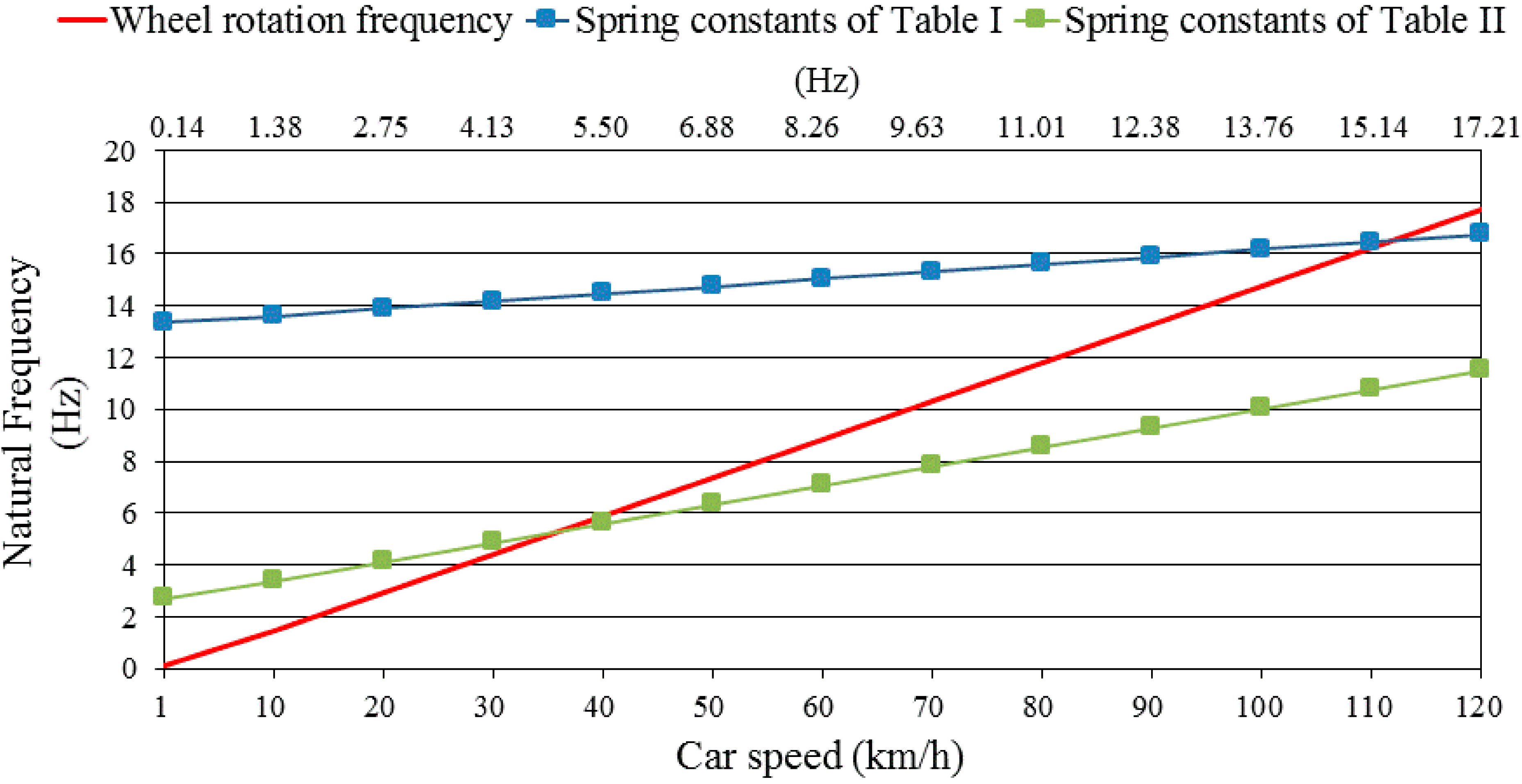
2.2. Natural Frequency of the NSEH

The general solution of Equation (6) can be derived as follows:
x ( t ) = C 1 · c o s ω d t + C 2 · sin ω d t + X · sin ( ω · t φ )
where ωd is the damped natural frequency, X is the amplitude of the steady-state vibration, φ is the phase angle caused by damping, and C1 and C2 are constants. For a low damping ratio, ωd is close to the natural frequency ωn, which can be expressed as follows:
ω n = k m
Substituting Equations (1) and (7) into Equation (9) and rearranging the equation results in:
ω n = ω r k 1 + k 2 ( k 1 L + δ k 2 L δ ) + r δ ( k 1 + k 2 ) ( k 3 + k 4 )
The spring constants and proof mass are usually selected such that δ is considerably lower than the spring length L; that is, Equation (10) can be approximated as follows:
ω n ω r ( k 1 k 2 ) L ( k 1 + k 2 ) + r ( k 3 + k 4 ) δ ( k 1 + k 2 )
The natural frequency of the energy harvester is determined according to the spring constants, length of the spring, distance between the wheel center and position of the energy harvester, and longitudinal displacement of the spring δ (which varies with the rotation speed of the wheel).

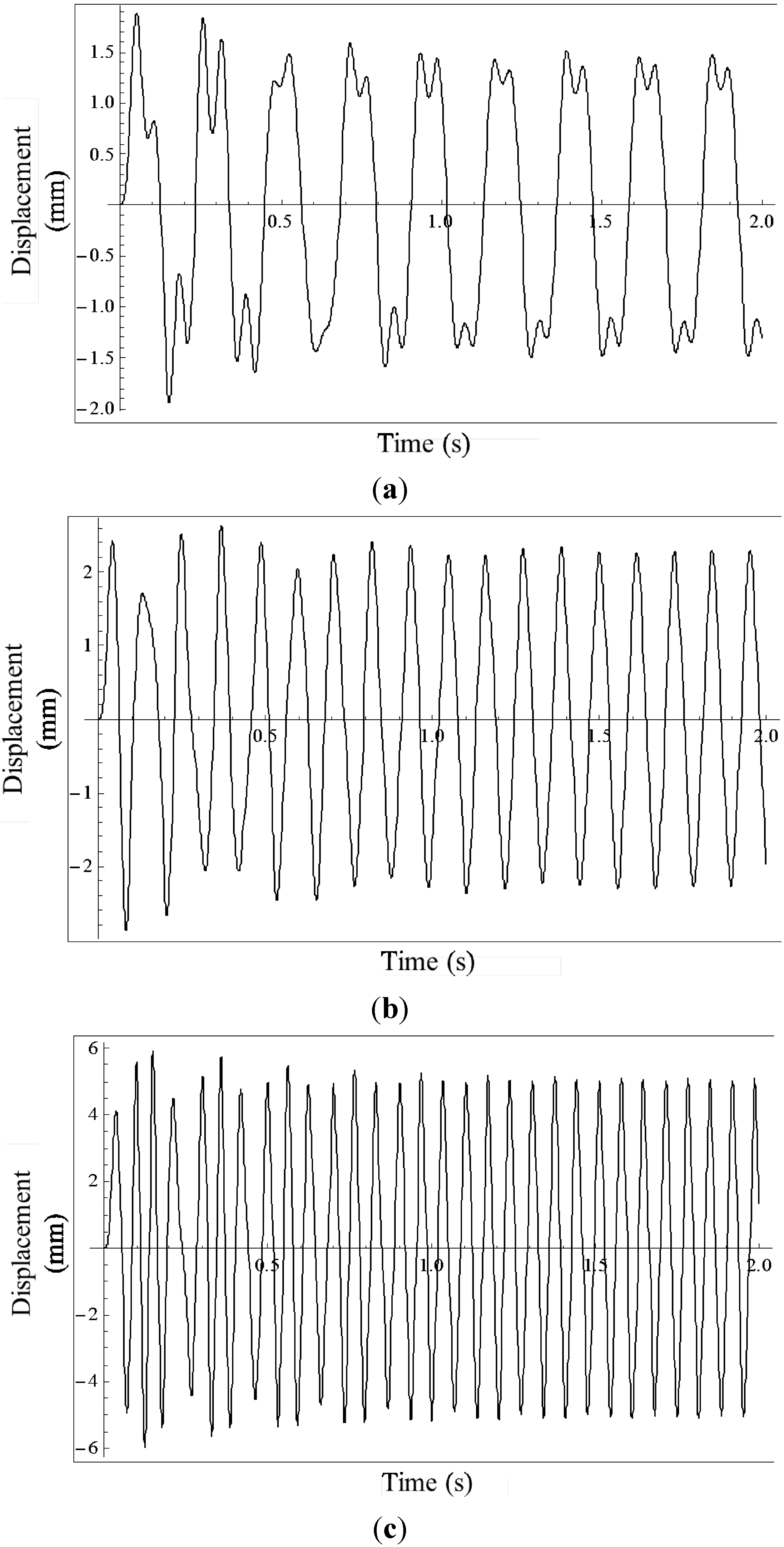
2.3. Numerical Results Obtained Using Analytical Models

The transverse oscillation of the mass demonstrates a nonlinear dynamic behavior and can be determined by using the Runge–Kutta method to solve Equation (3). Figure 3 shows the natural frequency of two NSEHs (Table 1 and Table 2) calculated using Equation (10). The slope and offset of the natural frequencies versus wheel speed were determined according to the values of the spring constant of the NSEHs. The natural frequency of a linear energy harvester that acquires a high quality factor only at a specific wheel speed is constant (i.e., it does not vary with the wheel speed). The natural frequency of the NSEH varies with the rotation speed of the wheel, thus resulting in nonlinear dynamic behavior. The blue line in Figure 3 indicates that the natural frequency of the NSEH (shown in Table 1) is equal to the rotation frequency of the wheel at 900 rpm. The green line indicates that the natural frequency of the other NSEH (shown in Table 2) is equal to the rotation frequency of the wheel at 300 rpm. Table 1 lists the parameters employed in the subsequent numerical calculation. The initial conditions are x ( 0 ) = 0 and x ˙ ( 0 ) = 0 . The diameter of the car wheel R was set to 0.3 m. Figure 4 shows the displacements of the proof mass, calculated using Equation (3), at different car speeds. The maximum displacements in a steady state are 1.6, 1.9, and 4.0 mm at wheel speeds of 30, 60, and 100 km/h, respectively. The wheel rotation frequencies of these speeds are 4.42, 8.84 and 14.74 Hz, respectively.
Figure 3. Comparison of the natural frequencies of two NSEHs (from Table 1 and Table 2) at various wheel speeds.
Micromachines 06 00312 g003
Table 1. Design parameters of the analytical model for high wheel speeds.
L (m)k1 (N/m)k2 (N/m)k3 (N/m)k4 (N/m)m (kg)r (m)R (m)C (N·s/m)
0.024030400035350.010.20.30.1
Table 2. Design parameters of the analytical model for low wheel speeds.
L (m)k1 (N/m)k2 (N/m)k3 (N/m)k4 (N/m)m (kg)r (m)R (m)C (N·s/m)
0.02123011701.41.40.010.20.30.1
Figure 4. Displacement variations of the proof mass at different car speeds: (a) 30 km/h, (b) 60 km/h, and (c) 100 km/h.
Micromachines 06 00312 g004

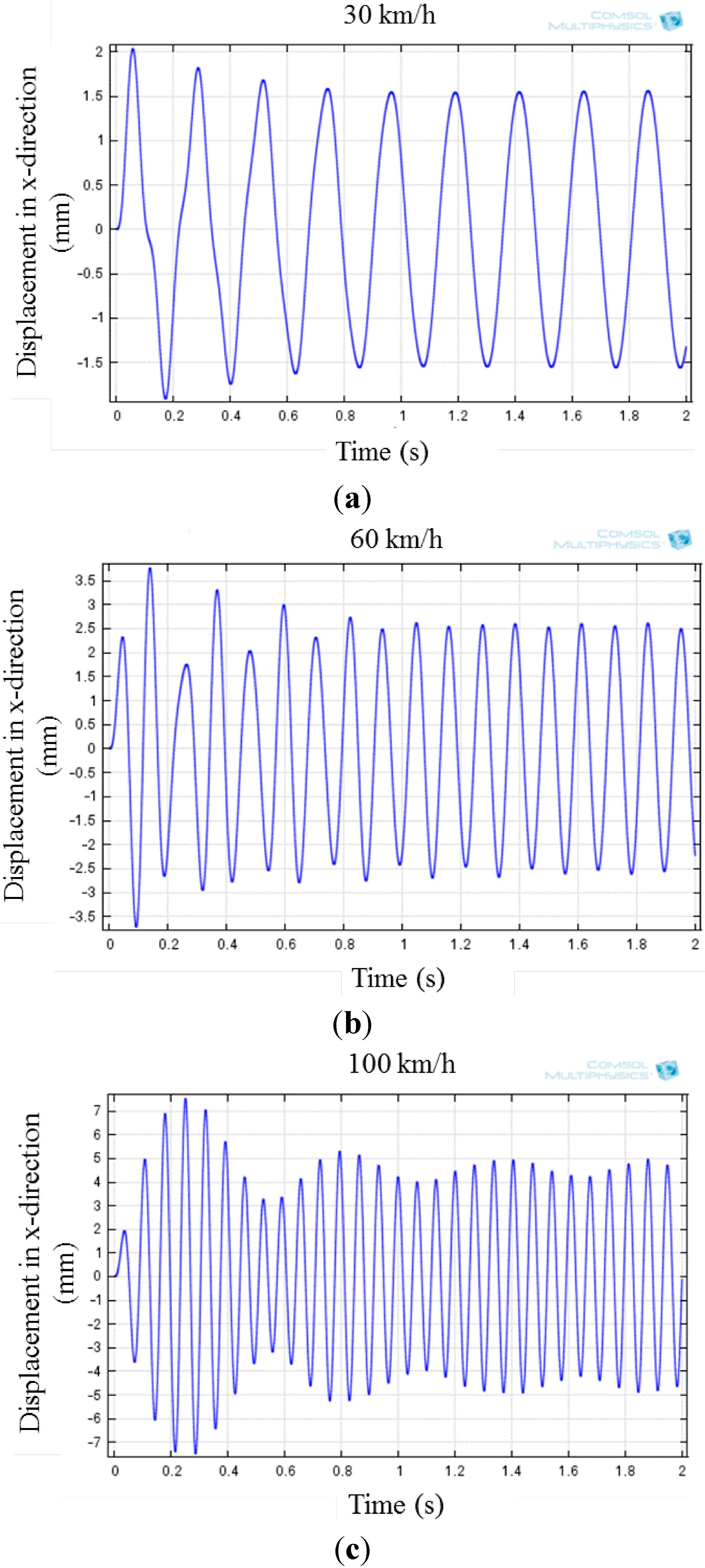
2.4. Numerical Results of the NSEH Obtained Using Finite Element Software

Figure 5a depicts a schematic diagram of the NSEH mounted on a car wheel as well as a magnified section of the schematic diagram. The springs comprise folded steel beams that are anchored to the side walls of the rim. To approach the values of the spring constants shown in Table 1, the dimensions of the two folded springs shown in Table 3 were used. Table 4 lists the spring constants of the prototype. The difference between the values shown in Table 1 and Table 4 is small because the significant digits and tolerance of the spring manufacturing process were in millimeters. The transverse oscillation of the proof mass of the prototype was simulated using COMSOL Multiphysics 4.2 (Burlington, MA, USA). The structure was constructed using the finite element method, and the gravitational and centrifugal forces were set using time-varied parameters. The damping constant and initial conditions were the same as those used in calculating the analytical model. Figure 5b illustrates a displacement simulation of the proof mass, which comprised two magnets and a plastic block. Figure 6 shows the displacements of the mass center of the prototype at different car speeds simulated using COMSOL. As shown in Figure 4 and Figure 6, the results obtained using the analytical model and COMSOL simulation are comparable in the steady state, verifying the accuracy of the analytical models and proving that the kinematic behaviors of the energy harvester are characterized by the parameters shown in Table 1. The discrepancy between the analytical model and COMSOL simulation are attributed to the geometrically nonlinear displacement and the simulation in COMSOL Multiphysics using the finite element method.
Figure 5. Displacement simulation of the prototype by using COMSOL Multiphysics 4.2. (a) Schematic diagram of the NSEH mounted on a car wheel. (b) Detailed structures and force load. (c) Half display of the displacement simulation results.
Micromachines 06 00312 g005
Figure 6. Variations of displacement of the prototype simulated using COMSOL at different car speeds: (a) 30 km/h, (b) 60 km/h, and (c) 100 km/h.
Micromachines 06 00312 g006
Table 3. Parameters of the folded springs for the prototype.
ItemLength in y directionWidth in x directionDepth in z directionDiameter of spring wireYoung’s Modulus
Upside and downside springs22 mm11 mm15 mm0.3 mm197 GPa
Table 4. Design parameters of the prototype in COMSOL.
L (m)k1 (N/m)k2 (N/m)k3 (N/m)k4 (N/m)m (kg)r (m)R (m)C (N·s/m)
0.024032400035.134.90.010.20.30.1

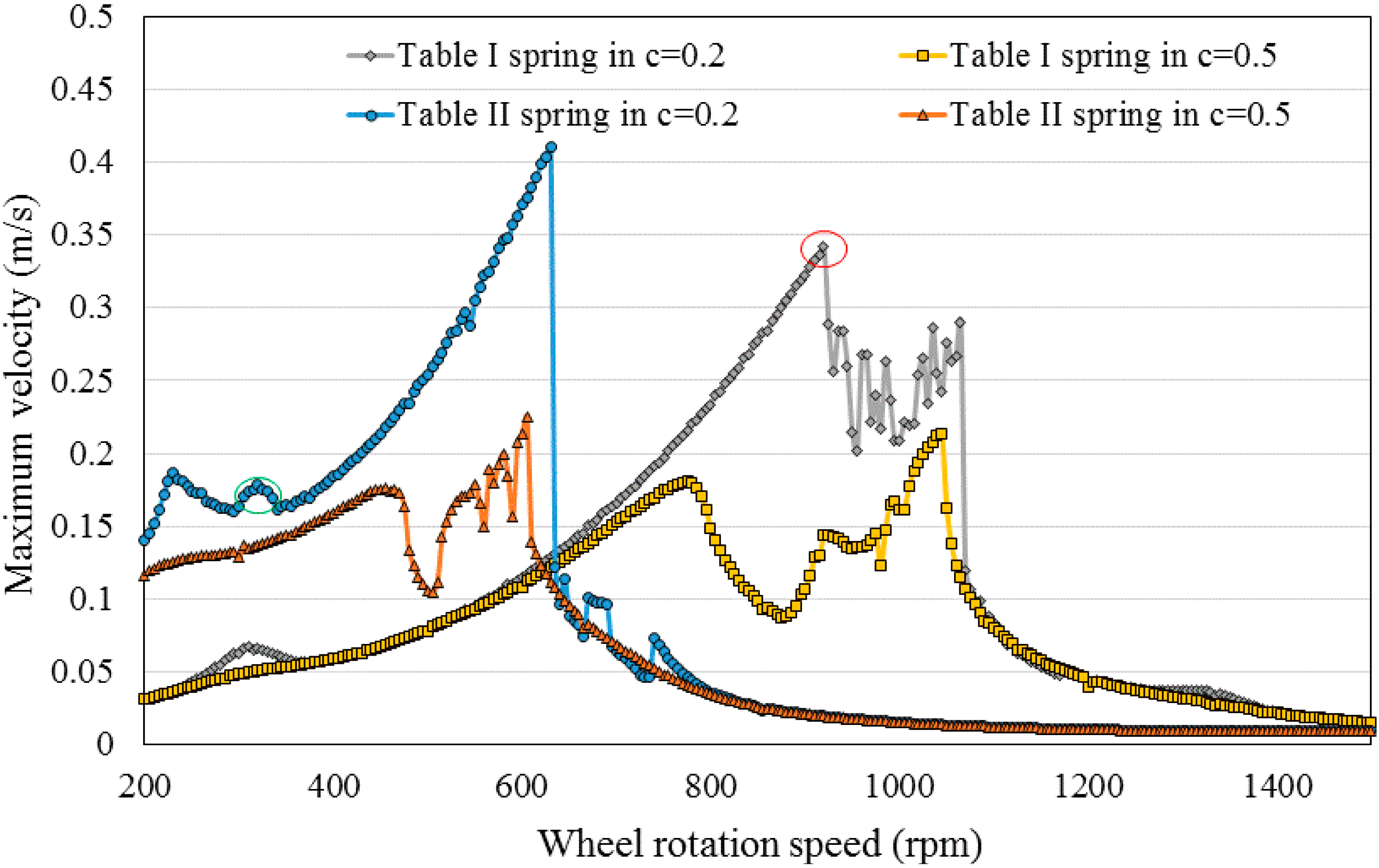
2.5. Frequency Domain Characteristics

The oscillatory motion of the NSEH driven by gravity exhibited nonlinear behavior. Figure 7 shows the variation of the maximum oscillation velocity of the proof mass in a steady state for various spring constants and electrical damping constants at different wheel rotation speeds. For the NSEH designed using the parameters shown in Table 1, the peak value of the maximum velocity was observed at wheel speeds ranging from 800 to 1050 rpm. For a low damping value (i.e., c = 0.2 N·s/m), the maximum oscillation velocity of the NSEH designed using the parameters shown in Table 1 was unstable at wheel speeds ranging from 900 to 1050 rpm. When the wheel speed was higher than 1050 rpm, the amplitude of the maximum velocity shifted to a lower value immediately. When the electrical damping constant was set to 0.5, the stability of the NSEH (designed using the parameters shown in Table 1) at high wheel speeds was more favorable than that obtained when the damping constant was set to 0.2. For the NSEH designed using the parameters shown in Table 2, the corresponding maximum oscillation velocity occurred at approximately 300 rpm; this is because the natural frequency of this NSEH was equal to the rotation rate of the wheel. When the electrical damping constant was low (i.e., c = 0.2), the amplitude of the maximum velocity displayed the jump phenomenon when the wheel speed was approximately 620 rpm. Moreover, the red and green circles indicate the primary resonant peaks of Table I and II springs respectively for c = 0.2 in Figure 7.
Figure 7. Frequency domain characteristics of NSEHs (of Table 1 and Table 2).
Micromachines 06 00312 g007

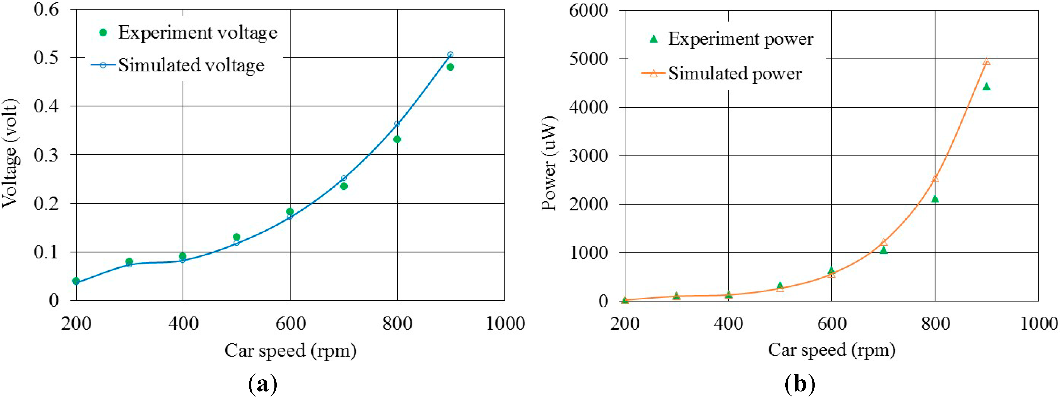
2.6. Output Voltage and Electromagnetic Damping

Figure 8a shows the magnetic field distribution of the NdFeB cylindrical magnet for the NSEH simulated in the x component by using Maxwell software. The residual magnetism, diameter, and length of the cylindrical magnet were 1.4 T, 8 mm, and 12 mm, respectively. The average external diameter and length of the wired coil set were 10 and 5 mm, respectively. The diameter of the coil wires was 0.1 mm. Figure 8b shows the magnetic flux density distribution for the line located at the central axis of the magnet; the distances to the central axis were d = 2.5 and d = 5. The simulation results of the proof mass oscillation indicated that the maximum displacement was lower than 5 mm at wheel speeds ranging from 100 to 1000 rpm. Therefore, the magnetic flux density distribution in the horizontal axis was considered ±5 mm from the left surface of the cylindrical magnet. Figure 8b depicts the average value of the magnetic flux density for d = 0, 5, and 10. The function of the average magnetic flux density was formulated as an approximate polynomial equation. The approximate polynomial equation was used for calculating dB/dx for the EMF ε and electromagnetic damping, where B is the average magnetic flux density.
The induced EMF ε for the coil sets in a magnetic field can be expressed as follows:
ε = d φ d t = d φ d x · d x d t = N · A · d B d x · d x d t
where φ is the magnetic flux. According to Faraday’s law, φ = N·B·A, where N is the number of turns and A is the cross-sectional area of the coil set. For an energy harvester series connected to an external load, the output voltage (VL) on the external load can be expressed as follows:
V L = ε R L R L + R C = N · A · d B d x · d x d t · R L R L + R C
where RL and RC represent the resistance of the external load and coil wires, respectively. The velocity (dx/dt) is the transverse oscillation velocity of the mass center. The magnetic force is one of the most dominant damping forces in the kinetic system. According to the energy conservation concept, Pe = Pm:
P e = ( d φ / d t ) 2 R L + R C = ( d φ / d x · d x / d t ) 2 R L + R C = P m = F e x ˙
where Pe and Pm represent the electric power and mechanical power, respectively. The force Fe caused by the electromagnetic damping to the proof mass can be expressed as follows:
F e = ( d φ / d x ) 2 R L + R C x ˙
Consequently, the electromagnetic damping constant ce caused by the relative velocity between the coil set and magnet can be expressed as follows:
c e = ( d φ / d x ) 2 R L + R C
Figure 8. Magnetic flux density simulation. (a) Magnetic field strength of the cylindrical magnet for the NSEH in the x component simulated using Maxwell. (b) Magnetic flux density distribution.
Micromachines 06 00312 g008

3. Experimental Results

A speed-controllable rotation plate was used to verify the power generation of the energy harvester. A rotating plate used as a wheel at constant speeds was driven by a servomotor connected to a motion-control card for setting the rotation speeds. The output voltage on the external load was transferred from the rotating plate to the oscilloscope through a slip ring. Figure 9 shows the prototype of the NSEH, which was fabricated according to the design parameters shown in Table 4. The material of the spring is stainless. The proof mass was fabricated using a cylindrical NdFeB magnet assembled using a polyoxymethylene block. Its weight was the same as that of the proof mass used in the simulation. The left and right cylindrical magnets were inserted into two plastic tubes, and the external surfaces of those plastic tubes were wrapped horizontally with coils to induce current.
The voltage across the resistor was measured using an oscilloscope, and the power consumed by the external resistor was calculated as the square of the root mean square of the voltage (Vrms) divided by the value of the external resistance (i.e., Pexp = (Vrms)2/RL). Furthermore, the electromagnetic damping constant Ce obtained from (16) was integrated into the following equation, and the numerical power consumption of the external resistor (Pnum) was calculated as follows:
P n u m = R L Γ ( R L + R C ) t 0 t 0 + Γ C e x ˙ 2 d t
where Γ is the oscillation period of the NSEH, and t0 is any given time in a steady state. Figure 10 shows the average power generation and instantaneous voltage output from the NSEH at various plate rotation speeds. The internal and load resistance were both 52 Ω. The maximum power was obtained when the load resistance matched the internal coil resistance. Each experimental datum was the average of five data sets. Both the numerical and experimental results indicated that the output voltage and electrical power obtained from the NSEH increased monotonically with the wheel speed; this is because of the high oscillation velocity of the magnets, which induced a high EMF ε. The difference between the numerical and experimental results regarding the voltage across the resistor was lower than that observed in the average power output because the power output contains the squared term of voltage. The difference between the simulation and experimental results regarding the output voltage was attributed to the gap between the coils and magnets. The gap value of the prototype in the experiments was higher than that in the simulation because of the assembly process and because the gap varied according to the car speed. In the future, the coil tube will be designed to move with the centrifugal force to maintain the gap at a constant value. The analytical power generation model employed for the numerical simulation, the results of which showed favorable consistency with the experimental results, was developed according to the models presented in this paper. The power output of the NSEH ranged from approximately 30 to 4200 μW at wheel speeds ranging from approximately 200 to 900 rpm. At higher wheel speeds, the output voltages in the simulation were larger than those in the experiment; this may be attributed to the high force of air drag that was induced by the small air gap between the magnets and coil sets.
Figure 9. Prototype of the NSEH.
Micromachines 06 00312 g009
Figure 10. Power generation and output voltage (RMS value). (a) Output voltage. (b) Output power.
Micromachines 06 00312 g010

4. Conclusions

This study proposes a novel device (denoted by NSEH) for harvesting energy from a rotating wheel. The device was modeled as a spring-mass system composed of a proof mass, two suspended springs, and two coil sets. Kinetic equations for estimating the oscillation velocity and calculating the output power were derived. Because of the variation in gravity when the wheel rotates, the proof mass demonstrated transverse vibration, and its natural frequency varied with the rotation speed of the wheel. The natural frequency of the NSEH was determined according to the stiffness of the two suspended springs. The accuracy of the kinematic equations was verified using the finite element method in COMSOL. The EMF and electromagnetic damping were also evaluated by simulating the magnetic field strength simulation and by using Faraday’s law. In the experiments, the power generation of the NSEH with a 52 Ω resistor connected in series ranged from nearly 30 to 4200 μW at wheel speeds ranging from approximately 200 to 900 rpm. Because the average power consumption of a TPMS is nearly 30 μW, the NSEH is a potential power supply for TPMSs.

Acknowledgments

The authors thank the Ministry of Science and Technology for providing the financial support for this research (grant number: MOST 103-2221-E-110-086 and 103-2218-E-110-009).

Author Contributions

The revised kinetic equations for the NSEH and numerical simulation in research were provided by Yu-Jen Wang; he also wrote the paper, and supervised the work in all stages. The original concept and model were initiated by Chung-De Chen. Chung-Chih Lin conducted experiments. The magnetic field strength simulation and prototype assembly were performed by Jui-Hsin Yu.

Conflicts of Interest

The authors declare no conflict of interest.

References

  1. Sodano, H.A.; Inman, D.J. A review of power harvesting from vibration using piezoelectric materials. Shock Vib. Dig. 2004, 36, 197–205. [Google Scholar] [CrossRef]
  2. Anton, S.R.; Sodano, H.A. A review of power harvesting using piezoelectric materials. Smart Mater. Struct. 2007, 16, R1–R21. [Google Scholar] [CrossRef]
  3. Roundy, S. On the effectiveness of vibration-based energy harvesting. J. Intell. Mater. Syst. Struct. 2005, 16, 809–823. [Google Scholar] [CrossRef]
  4. Moon, K.S.; Liang, H.; Yi, J.; Mika, B. Tire tread deformation sensor and energy harvester development for smart tire application. Proc. SPIE 2007, 6529, 65290K. [Google Scholar]
  5. Karami, M.A.; Inman, D.J. Equivalent damping and frequency change for linear and nonlinear hybrid vibrational energy harvesting systems. J. Sound Vib. 2011, 330, 5583–5597. [Google Scholar] [CrossRef]
  6. Pan, C.T.; Wu, T.T. Development of a rotary electromagnetic microgenerator. J. Micromech. Microeng. 2007, 17, 120–128. [Google Scholar] [CrossRef]
  7. Arnold, D.P. Review of microscale magnetic power generation. IEEE Trans. Magn. 2007, 43, 3940–3951. [Google Scholar] [CrossRef]
  8. Wickenheiser, A.M.; Reissman, T.; Wu, W.J.; Garcia, E. Modeling the effects of electromechanical coupling on energy storage through piezoelectric energy harvesting. IEEE/ASME Trans. Mechatron. 2010, 15, 400–411. [Google Scholar] [CrossRef]
  9. Leland, E.S.; Wright, P.K. Resonance tuning of piezoelectric vibration energy scavenging generators using compressive axial preload. Smart Mater. Struct. 2006, 15, 1413–1420. [Google Scholar] [CrossRef]
  10. Platt, S.R.; Farritor, S.; Haider, H. On low-frequency electric power generation with PZT ceramics. IEEE/ASME Trans. Mechatron. 2005, 10, 240–252. [Google Scholar] [CrossRef]
  11. Erturk, A.; Inman, D.J. An experimentally validated bimorph cantilever model for piezoelectric energy harvesting from base excitations. Smart Mater. Struct. 2009, 18, 105019. [Google Scholar] [CrossRef]
  12. Hobeck, J.D.; Inman, D.J. Artificial piezoelectric grass for energy harvesting from turbulence-induced vibration. Smart Mater. Struct. 2012, 21, 105024. [Google Scholar] [CrossRef]
  13. Dai, H.L.; Abdelkefi, A.; Wang, L. Theoretical modeling and nonlinear analysis of piezoelectric energy harvesting from vortex-induced vibrations. J. Intell. Mater. Syst. Struct. 2014. [Google Scholar] [CrossRef]
  14. Marzencki, M.; Defosseux, M.; Basrour, S. MEMS vibration energy harvesting devices with passive resonance frequency adaptation capability. J. Microelectromech. Syst. 2009, 18, 1444–1453. [Google Scholar] [CrossRef]
  15. Koh, S.J.A.; Keplinger, C.; Li, T.; Bauer, S.; Suo, Z. Dielectric elastomer generators: How much energy can be converted. IEEE/ASME Trans. Mechatron. 2011, 16, 33–41. [Google Scholar] [CrossRef]
  16. Williams, C.B.; Yates, R.B. Analysis of a micro-electric generator for microsystems. Sens. Actuators A Phys. 1996, 52, 8–11. [Google Scholar] [CrossRef]
  17. Nguyen, D.S.; Halvorsen, E.; Jensen, G.U.; Vogl, A. Fabrication and characterization of a wideband MEMS energy harvester utilizing nonlinear springs. J. Micromech. Microeng. 2010, 20, 125009. [Google Scholar] [CrossRef]
  18. Xing, X.; Lou, J.; Yang, G.M.; Obi, O.; Dirscoll, C.; Sun, N.X. Wideband vibration energy harvester with high permeability magnetic material. Appl. Phys. Lett. 2009, 95, 134103. [Google Scholar] [CrossRef]
  19. Daqaq, M.F. On intentional introduction of stiffness nonlinearities for energy harvesting under white Gaussian excitations. Nonlinear Dyn. 2012, 69, 1063–1079. [Google Scholar] [CrossRef]
  20. Zheng, R.; Nakano, K.; Hu, H.; Su, D.; Cartmell, M.P. An application of stochastic resonance for energy harvesting in a bistable vibrating system. J. Sound Vib. 2014, 333, 2568–2587. [Google Scholar] [CrossRef]
  21. Zhu, D.; Robert, S.; Tudor, M.J.; Beeby, S.P. Design and experimental characterization of a tunable vibration-based electromagnetic micro-generator. Sens. Actuators A Phys. 2010, 158, 284–293. [Google Scholar] [CrossRef]
  22. Wischke, M.; Masur, M.; Goldschmidtboeing, F.; Woias, P. Electromagnetic vibration harvester with piezoelectrically tunable resonance frequency. J. Micromech. Microeng. 2010, 20, 035025. [Google Scholar] [CrossRef]
  23. Masana, R.; Daqaq, M.F. Electromechanical Modeling and Nonlinear Analysis of Axially Loaded Energy Harvesters. J. Sound Vib. 2011, 133, 011007. [Google Scholar]
  24. Abdelkefi, A.; Barsallo, N. Comparative modeling of low-frequency piezomagnetoelastic energy harvesters. J. Intell. Mater. Syst. Struct. 2014. [Google Scholar] [CrossRef]
  25. Ching, N.N.H.; Wong, Y.; Li, W.J.; Leong, P.H.W.; Wen, Z.Y. A laser-micromachined multi-modal resonating power transducer for wireless sensing systems. Sens. Actuators A Phys. 2002, 97–98, 685–690. [Google Scholar]
  26. Yang, B.; Lee, C.; Xiang, W.; Xie, J.; He, J.H.; Kotlanka, R.K.; Low, S.P.; Feng, H. Electromagnetic energy harvesting from vibrations of multiple frequencies. J. Micromech. Microeng. 2009, 19, 035001. [Google Scholar] [CrossRef]
  27. Singh, K.B.; Bedekar, V.; Taheri, S.; Priya, S. Piezoelectric vibration energy harvesting system with an adaptive frequency tuning mechanism for intelligent tires. Mechatronics 2012, 27, 970–988. [Google Scholar] [CrossRef]
  28. Wu, X.; Parmar, M.; Lee, D.W. A Seesaw-Structured Energy Harvester with Superwide Bandwidth for TPMS Application. IEEE/ASME Trans. Mechatron. 2013, 19, 1514–1522. [Google Scholar]
  29. Lee, J.; Choi, B. Development of a piezoelectric energy harvesting system for implementing wireless sensors on the tires. Energy Convers. Manag. 2014, 78, 32–38. [Google Scholar] [CrossRef]
  30. Wang, Y.J.; Chen, C.D.; Sung, C.K. System design of a weighted-rotor type electromagnetic generator for harvesting energy from a rotating wheel. IEEE/ASME Trans. Mechatron. 2013, 18, 754–763. [Google Scholar] [CrossRef]
  31. Wang, Y.J.; Chen, C.D. Design and jump phenomenon analysis of an eccentric ring energy harvester. Smart Mater. Struct. 2013, 22, 105019. [Google Scholar] [CrossRef]
  32. Wang, Y.J.; Chen, C.D.; Sung, C.K. Design of a frequency-adjusting device for harvesting energy from a rotating wheel. Sens. Actuators A Phys. 2010, 159, 196–203. [Google Scholar] [CrossRef]
  33. Wang, Y.J.; Chen, C.D.; Sung, C.K.; Li, C. Natural Frequency Self-tuning Energy Harvester using a Circular Halbach Array Magnetic Disk. J. Intell. Mater. Syst. Struct. 2012, 23, 933–943. [Google Scholar] [CrossRef]

