
A Compact W-Band Reflection-Type Phase Shifter with Extremely Low Insertion Loss Variation Using 0.13 µm CMOS Technology

Abstract
:1. Introduction

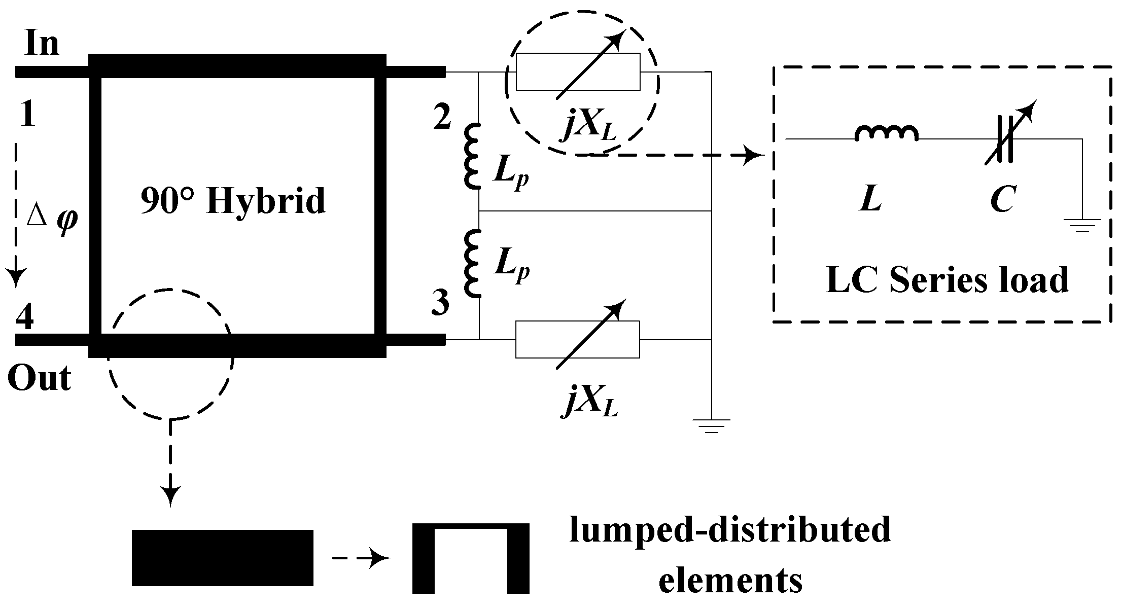
2. Design Concept

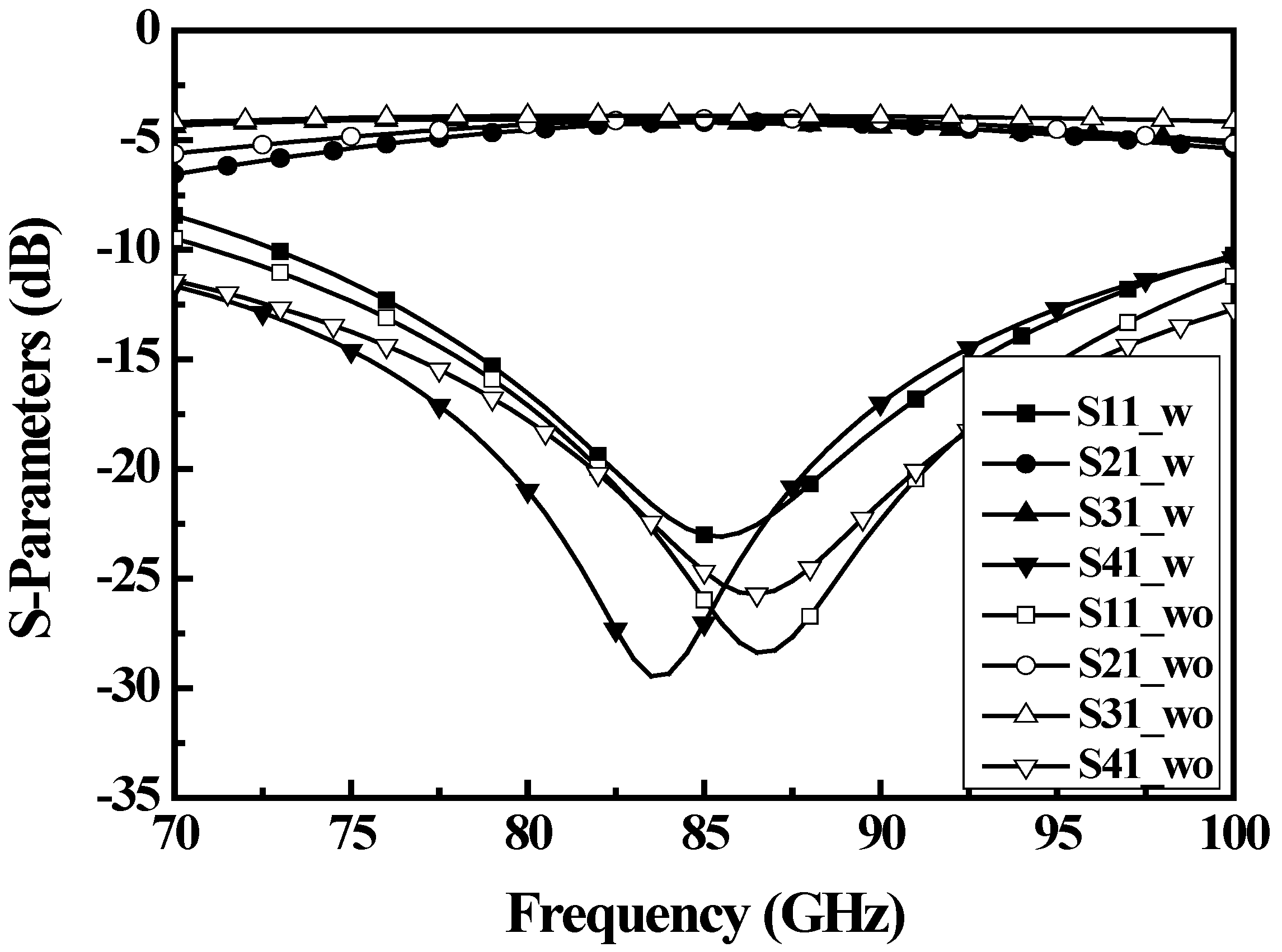
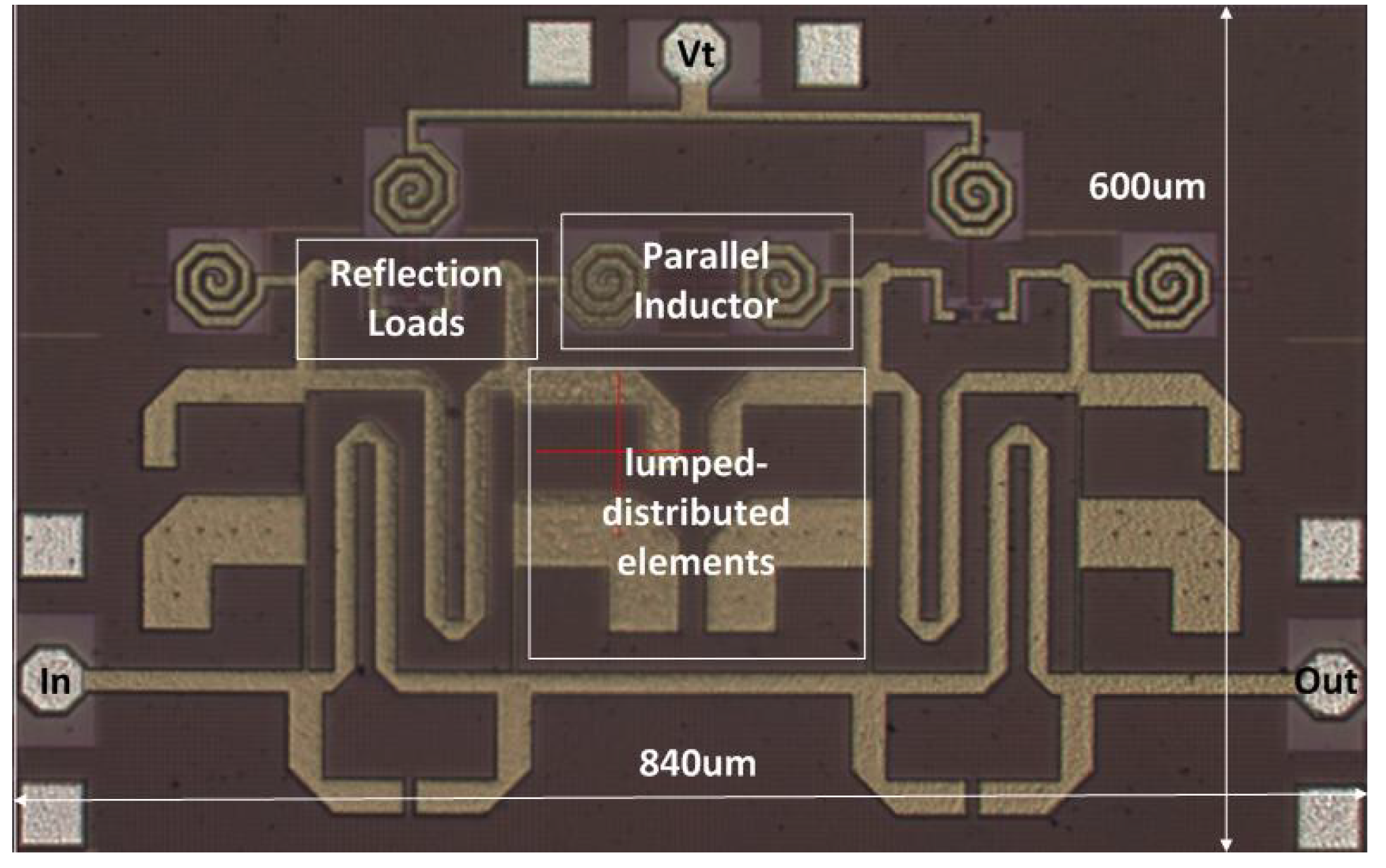
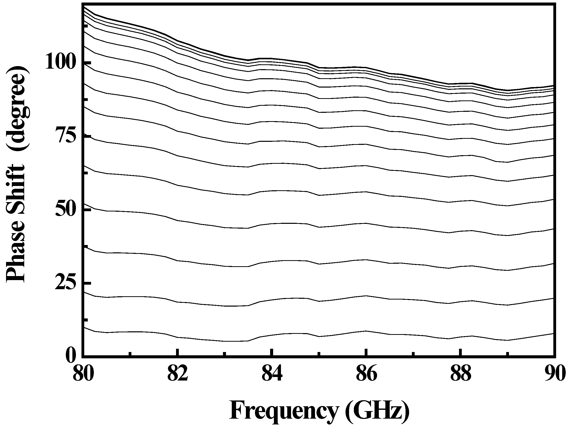
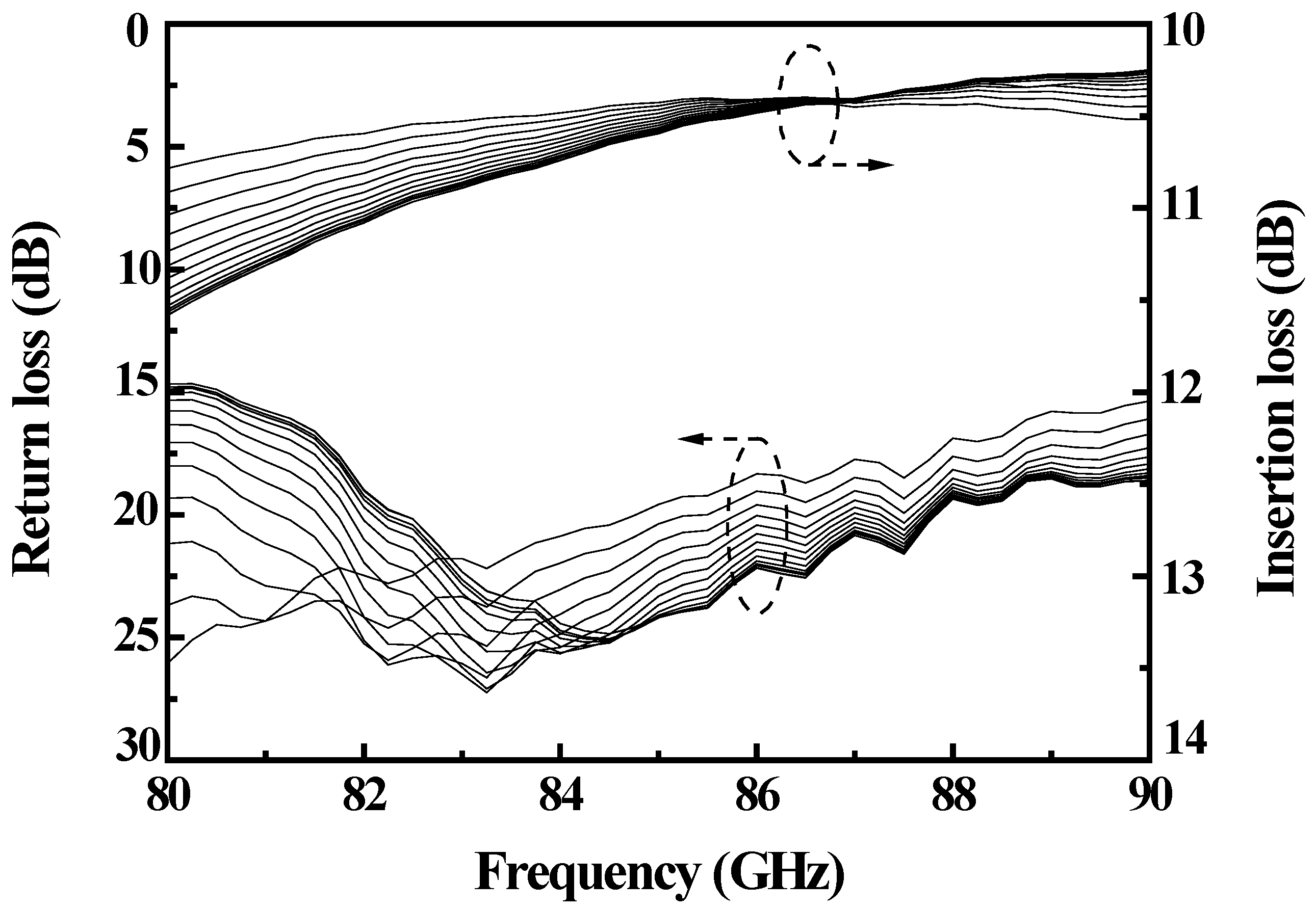
3. Measurement


| Reference | Technology | Frequency (GHz) | Phase Shift | Insertion Loss Variation | Chip Area (mm2) |
|---|---|---|---|---|---|
| [3] | 0.18 µm CMOS | 24 | 360° | 10.1–12.5 dB (±1.2 dB, ±10.6%) | 0.33 |
| [6] | 0.18 µm CMOS | 60 | 270° | 9.8–14.8 dB (±2.5 dB, ±20.3%) | 0.18 |
| [7] | 0.13 µm CMOS | 60 | 100° | 5.1–7.8 dB (±1.35 dB, ±20.9%) | 0.2 |
| [8] | 0.12 µm BiCMOS | 94 | 65° | 7–14 dB (±3.5 dB, ±33%) | 0.21 |
| This work | 0.13 µm CMOS | 80 | 119° | 10.5–11.5 dB (±0.5 dB, ±4.5%) | 0.51 |
| 86 | 101° | 10.4–10.5 dB (±0.05 dB, ±0.5%) | |||
| 90 | 92° | 10.25–10.75 (±0.25 dB, 2.4%) |
4. Conclusions
Author Contributions
Conflicts of Interest
References
- Wang, J.; Yang, L.; Liu, Y.; Wang, Y.; Gong, S. Design of a Wideband Differential Phase Shifter with the Application of Genetic Algorithm. Prog. Electromagn. Res. Lett. 2014, 48, 45–59. [Google Scholar] [CrossRef]
- Wang, Z.G.; Yan, B.; Xu, R.M.; Guo, Y.C. Design of a Ku Band Six Bit Phase Shifter using Periodically Loaded-line and Switched-line with Loaded-line. Prog. Electromagn. Res. Lett. 2007, 76, 369–379. [Google Scholar] [CrossRef]
- Wu, J.C.; Chang, C.C.; Chang, S.F.; Chin, T.Y. A 24-GHz Full-360° CMOS Reflection-Type Phase Shifter MMIC with Low Loss-Variation. In Proceedings of IEEE 2008 Radio Frequency Integrated Circuits Symposium (RFIC), Atlanta, GA, USA, 15–17 June 2008; pp. 365–368.
- Lin, C.S.; Chang, S.F.; Chang, C.C.; Shu, Y.H. Design of a Reflection-Type Phase Shifter with Wide Relative Phase Shift and Constant Insertion Loss. IEEE Trans. Microw. Theory Tech. 2007, 55, 1862–1868. [Google Scholar] [CrossRef]
- Wu, J.C.; Chin, T.Y.; Chang, S.F.; Chang, C.C. 2.45-GHz CMOS Reflection-Type Phase-Shifter MMICs with Minimal Loss Variation over Quadrants of Phase-Shift Range. IEEE Trans. Microw. Theory Tech. 2008, 56, 2180–2189. [Google Scholar] [CrossRef]
- Su, Y.S.; Tsai, M.C.; Wu, J.C.; Chin, T.Y.; Chang, C.C. A V-/W Band 0.18-µm CMOS Phase Shifter MMIC with 180°–300° Phase Tuning Range. In Proceedings of 2012 Asia-Pacific Microwave Conference Proceedings (APMC), Kaohsiung, Taiwan, 4–7 December 2012; pp. 91–93.
- Choi, S.H.; Lee, Y.M.; Kim, M. 60 GHz reflection-type phase shifter using 0.13-µm CMOS body-floating switches. Electron. Lett. 2011, 47, 701–702. [Google Scholar] [CrossRef]
- Mehmet, P.; James, F.B. A Low-Power, W-Band Phase Shifter in a 0.12-µm SiGe BiCMOS Process. IEEE Microw. Wirel. Compon. Lett. 2010, 20, 631–633. [Google Scholar] [CrossRef]
- Chen, C.; Wu, H.; Wu, W. Design and Implementation of a Compact Planar 4 × 4 Microstrip Butler Matrix for Wideband Application. Prog. Electromagn. Res. Lett. C 2011, 24, 43–55. [Google Scholar] [CrossRef]
© 2015 by the authors; licensee MDPI, Basel, Switzerland. This article is an open access article distributed under the terms and conditions of the Creative Commons Attribution license (http://creativecommons.org/licenses/by/4.0/).
Share and Cite
Deng, X.-D.; Li, Y.; Wu, W.; Xiong, Y.-Z. A Compact W-Band Reflection-Type Phase Shifter with Extremely Low Insertion Loss Variation Using 0.13 µm CMOS Technology. Micromachines 2015, 6, 390-395. https://doi.org/10.3390/mi6030390
Deng X-D, Li Y, Wu W, Xiong Y-Z. A Compact W-Band Reflection-Type Phase Shifter with Extremely Low Insertion Loss Variation Using 0.13 µm CMOS Technology. Micromachines. 2015; 6(3):390-395. https://doi.org/10.3390/mi6030390
Chicago/Turabian StyleDeng, Xiao-Dong, Yihu Li, Wen Wu, and Yong-Zhong Xiong. 2015. "A Compact W-Band Reflection-Type Phase Shifter with Extremely Low Insertion Loss Variation Using 0.13 µm CMOS Technology" Micromachines 6, no. 3: 390-395. https://doi.org/10.3390/mi6030390