Article

A Novel Transdermal Power Transfer Device for the Application of Implantable Microsystems

National Key Laboratory of Science and Technology on Micro/Nano Fabrication, Key Laboratory of Shanghai Education Commission for Intelligent Interaction and Cognitive Engineering, Department of Micro/Nano-electronics, Shanghai Jiao Tong University, Shanghai 200240, China
*
Author to whom correspondence should be addressed.
Micromachines 2015, 6(3), 396-408; https://doi.org/10.3390/mi6030396
Submission received: 25 December 2014 / Revised: 4 March 2015 / Accepted: 18 March 2015 / Published: 23 March 2015
(This article belongs to the Special Issue Power MEMS)

Abstract

:
This paper presents a transdermal power transfer device for the application of implantable devices or systems. The device mainly consists of plug and socket. The power transfer process can be started after inserting the plug into the socket with an applied potential on the plug. In order to improve the maneuverability and reliability of device during power transfer process, the metal net with mesh structure were added as a part of the socket to serve as intermediate electrical connection layer. The socket was encapsulated by polydimethylsiloxane (PDMS) with good biocompatibility and flexibility. Two stainless steel hollow needles placed in the same plane acted as the insertion part of the needle plug, and Parylene C thin films were deposited on needles to serve as insulation layers. At last, the properties of the transdermal power transfer device were tested. The average contact resistance between needle and metal mesh was 0.454 Ω after 50 random insertions, which showed good electrical connection. After NiMH (nickel-metal hydride) batteries were recharged for 10 min with current up to 200 mA, the caused resistive heat was less than 0.6 °C, which also demonstrated the low charging temperature and was suitable for charging implantable devices.

1. Introduction

Implantable microsystems are widely used in biomedical engineering for diagnostics and monitoring [1,2,3], drug delivery [4,5,6,7], artificial prosthesis [8,9,10,11], and so on. A typical implantable microsystem usually contains three parts. The first part is a sensor or actuator unit used for recording signals or stimulating nerve cells. The second one is a control unit used for signal processing and generating. And the last one is a power unit used for supplying power.
Figure 1a shows conceptual diagram of the typical implantable microsystem [12]. The power supply unit plays a very important role in implantable microsystems due to its effect on the lifetime of the systems [13,14,15,16]. Nowadays, there are two kinds of power supply units widely applied in implantable microsystems, which are primary batteries [17] and rechargeable batteries [18,19,20,21]. As to long-term implantation of implantable microsystems for several decades, primary batteries are limited due to their limited battery capacity [22,23,24,25,26]. In cardiac pacing systems, heart failure might cause casualties due to the depletion of the batteries before replacement [27,28,29]. However, the replacement of batteries will increase the cost, the risk and suffering of patients. Rechargeable batteries for microsystems provide a good alternative to solve this problem. For non-invasive purposes, most implantable microsystems are recharged by wireless power transfer method [18,19,20,30,31,32,33]. However, the wireless recharging method with relatively low power transmission efficiency will lead to a very long charging time. Meanwhile, the electromagnetic radiation produced by wireless power transfer might cause skin and tissue injury, even the potential risk of cancer. As to high power consumption systems, transdermal power transfer method has some advantages, such as micro-invasive characteristics, high power transmission efficiency and low charging temperature [21,32,34,35,36,37,38,39]. Transdermal power transfer devices charged by small needles, which could lead to a small injury compared with wireless power transfer device, because electromagnetic radiation injury produced by wireless power transfer is much worse than the temperature increase; the literature mentioned above did not talk about the effects of the temperature increase.
Although the transdermal recharging method has the risk of causing skin infection during charging process, this risk can be eliminated by sterilizing the insertion needle as well as the injection of saline. Furthermore, several hours of power transfer by transdermal recharging can keep an implantable system working for several years. At present, the emerged transdermal recharging device usually contains two parts. One part is the plug used for the connection with the external power supply. The other one is the socket implanted in vivo used for the connection with the internal power supply. The socket with two metal contact-springs acts as an intermediate electrical connection layers, which might lead to poor maneuverability due to its misalignment after implantation in vivo. The plug is fabricated by coating Parylene C thin film on a hollow metal needle. However, due to its double-layer structure of metal contact-springs, the coating might be scratched during the insertion process.
In this paper, a novel type of transdermal power transfer device for implantable device application is presented. Figure 1b shows the schematic diagram of the proposed transdermal power transfer system. The socket with two pieces of metal nets placed in the same plane was encapsulated by polydimethylsiloxane (PDMS), realizing good maneuverability, reliable electrical connection and thickness reduction of the device. The needle part of the plug was fabricated by two hollow metal needles coated with Parylene C thin films to serve as an insulation layer. Finally, the electrical connection, waterproofness, penetrating force, recharging temperature and effectiveness of device were tested, respectively.
Figure 1. (a) The conceptual diagram of a typical implantable microsystem and (b) the schematic diagram of the proposed transdermal power transfer system.
Micromachines 06 00396 g001

2. Experimental Section

2.1. Design

A device with the following properties was desired: easy recharging, good biocompatibility, waterproof, non- or micro-invasive, low charging temperature, etc. PDMS and Parylene C have good biocompatibility and flexibility and have been widely used in implantable microsystems for encapsulation [40,41,42]. Figure 2 shows the schematic diagram of the transdermal power transfer device. Combined with Figure 1b, we chose litz wire with 38 AWG (American Wire Gage) and the designed maximum current was 500 mA. Since the devices were well encapsulated, we used the DC current for charging after a careful examination. This is a suitable, safe recharging method for implantable applications. By using the interference fit between needles and stainless steel nets, reliable electrical connection and good maneuverability during power transfer process was obtained. The power transfer process can be started after inserting the plug into the socket with an applied recharging potential on the plug as shown in Figure 2a. Two pieces of stainless steel net, for the sockets, were placed in the same plane and used for connecting to the cathode and anode of the internal power supply, respectively.
The socket was encapsulated in a PDMS encapsulation shell as shown in Figure 2b. The plug was fabricated by the installation of two stainless steel hollow needles in the plastic plane. A Parylene C thin film used as insulation layer was chemical vapor deposited (CVD) on needles. To decrease the charging temperature, the plug was designed with a notch on the plastic plane as shown in Figure 2c. The notch part of the needles with air around them will lead to a better cooling effect compared to encapsulate in PDMS. Due to the mesh structure of metal nets, the needle plug can be easily inserted into the socket through the skin. In particular, it could form an electrical connection with the nets at any point over the connection area. Because the mesh size of this metal net is a little smaller than the outer diameter of the needles, the interference fit can ensure reliable electrical connection between the plug and socket. Meanwhile, the designed distance between two needles should be larger than the width of the metal net to avoid a short circuit when two needles are inserted into one piece of the metal net. The mesh plates are 0.5 cm in length and width. The mesh plate is flexible and its thickness is 0.2 mm. Because the mesh plate is encapsulated in a PDMS encapsulation shell and its material is biocompatible, it can be implanted permanently. The penetration of the metal needles is similar to a needle injection. Thus, the resulting pain or infection of skin is acceptable, same as a needle injection.
Figure 2. Conceptual diagram of the typical implantable microsystem. The schematic of the transdermal power transfer device. (a) The schematic of transdermal power transfer process. The process can be started after the insertion of the plug into the socket then applying a certain recharging potential to the plug. (b) The schematic of socket part. The stainless steel nets, with mesh size of 0.5 mm, match with the needle plug and form a good electrical connection. The whole plug was encapsulated by polydimethylsiloxane (PDMS) by cast method. (c) The schematic of plug. Parylene C thin film (5 µm) was chemical vapor deposited on needles for insulation and the notch on plastic plane was designed to decrease the recharging temperature.
Micromachines 06 00396 g002

2.2. Fabrication

Figure 3a shows the fabrication process of the socket. First, the PDMS (Sylgard® 184, Dow Corning, Midland, MI, USA) mixture (Base:Curing Agent = 10:1) was prepared. Then the PDMS packaging shell without cover was fabricated using a casting method with a curing process at the temperature of 75 °C for 3 h. The thickness of the PDMS film used for device packaging is 0.15 cm. The length, width and the height of the cuboid shell were 20 mm, 10 mm and 3 mm, respectively.
Figure 3. The fabrication process of device. (a) The fabrication process of the plug. (b) The fabrication process of socket.
Micromachines 06 00396 g003
Second, the two pieces of stainless steel net, with a mesh size of 0.5 mm, were connected to lead wires. After that, they were placed in the PDMS shell in the same plane. Last, the PDMS cover was casted to create a whole-packaging shell. Figure 3b shows the fabrication process of the plug. First, a plastic plane with notches was prepared. Second, two holes with diameter of 0.6 mm were drilled on the notch position for the installation of needles. Third, the needles with diameter of 0.55 mm were installed in plastic plane and stuck with glue. Fourth, 5 μm of Parylene C thin film was chemical vapor deposited (Parylene deposition system (PDS) 2010, Specialty Coating Systems (SCS), Indianapolis, IN, USA) on the needles as an insulation layer. The tips of the needles are rubbed on a friction plate to remove the Parylene. Last, the needles were connected to the metal plug for easy connection to an external power supply. Figure 4a,b shows the fabricated socket and plug.
Figure 4. The fabricated device. (a) The fabricated socket with two pieces of stainless steel net inside. (b) The fabricated plug with two needles.
Micromachines 06 00396 g004

3. Results and Discussion

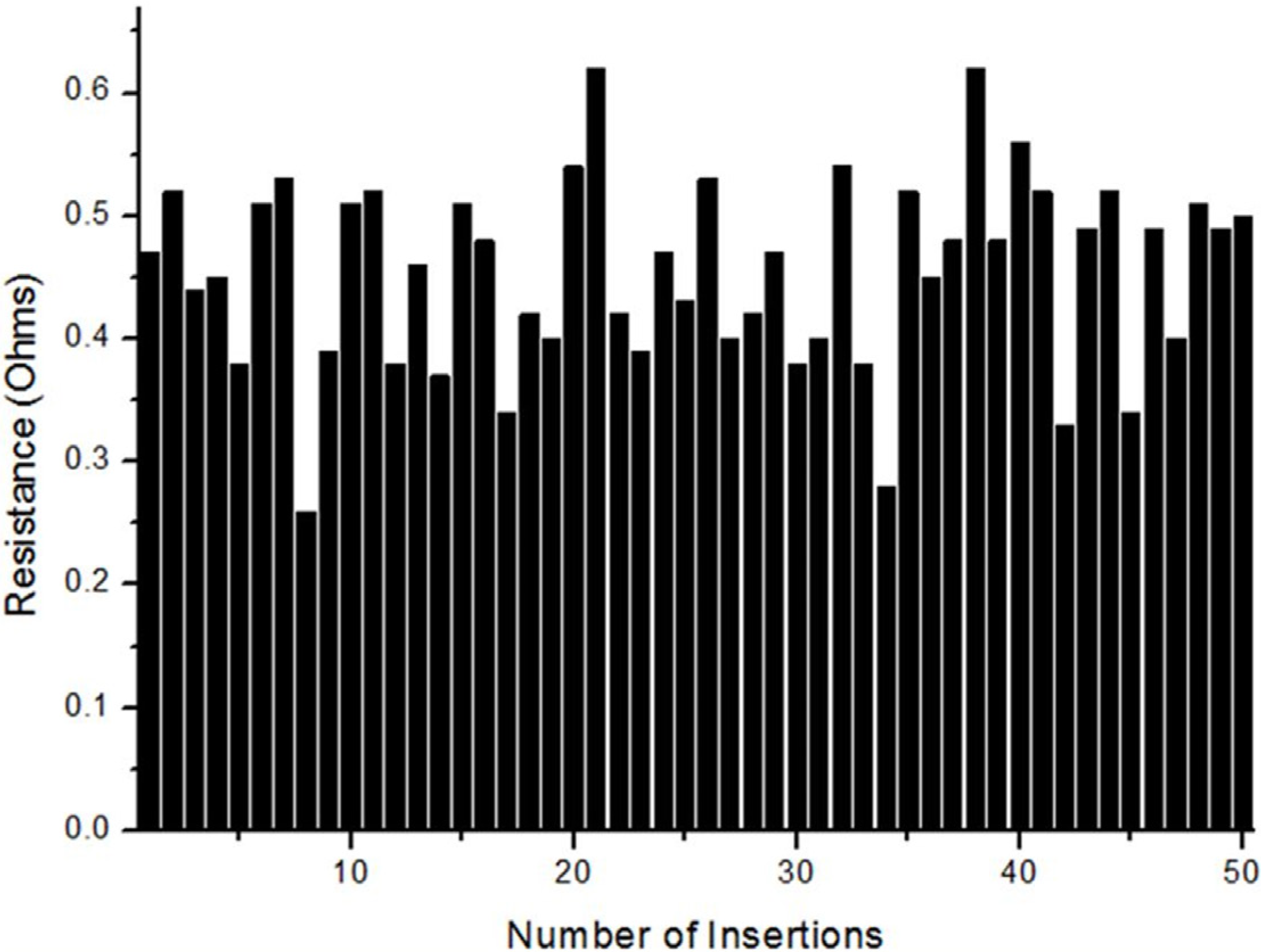
3.1. Electrical Connection
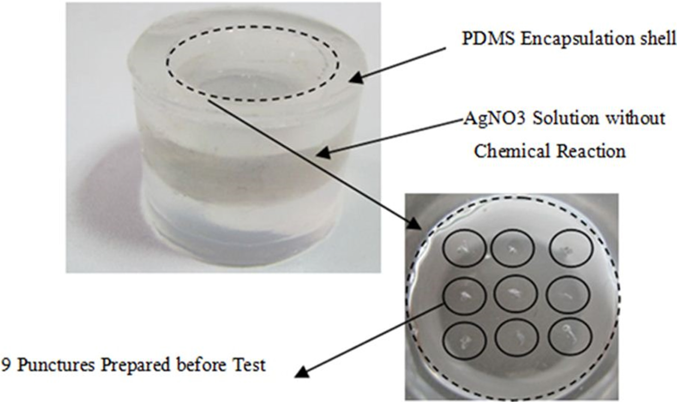
The transdermal power transfer device with good reliability can result in stable power transfer. Good maneuverability of the device also affects its practicality. Because of the interference fit between stainless steel nets (mesh size = 0.5 mm) and needle plug (diameter = 0.55 mm), the good electrical connection could be formed. In order to evaluate electrical connection reliability and maneuverability, the contact resistances between needle and stainless steel net were investigated with 50 random insertions. Figure 5 shows the contact resistances between single needle and stainless steel net over 50 random insertions. The resistance varies from 0.26 to 0.62 Ω. The average contact resistance of 0.454 Ω can be calculated from the data. Figure 6a,b shows the status of PDMS encapsulation shell and stainless steel net after 50 times random insertions.
Figure 5. The contact resistances between single needle and stainless steel over 50 random insertions. The resistance varies from 0.26 to 0.62 Ω. The average contact resistance of 0.454 Ω can be calculated from the data.
Micromachines 06 00396 g005
Figure 6. The pictures of PDMS (a) and stainless steel net (b) after 50 random insertions.
Micromachines 06 00396 g006

3.2. Waterproofness

Implantable devices with good waterproofness would prevent the infiltration of tissue fluid for inner structure protection. Implantable microsystems are recharged many times after implantation and during each recharging process the PDMS encapsulation shell could be punctured again, which would increase the possibility of the infiltration of tissue fluid. The thickness of PDMS film used for waterproofness test is same as the device package. The waterproofness test was taken by injecting 0.1 M AgNO3 solution into a cylindrical PDMS packaging shell and then dipping it into 0.9% NaCl solution for 10 months at room temperature. Figure 7 shows the status of the PDMS encapsulation shell after dipping into 0.9% NaCl solution for 10 months. Before testing, a PDMS packaging shell with nine punctures was prepared to simulate the real situation. A white precipitate of silver nitrate (AgCl) would be produced if the NaCl solution infiltrated the PDMS encapsulation shell. The chemical change can be explained by the following equation:
AgNO3 + NaCl = AgCl↓ + NaNO3
Figure 7. The status of the PDMS encapsulation shell after dipping into 0.9% NaCl solution for five months. After five months of dipping, there was no white precipitate generated. Nine punctures (solid line circles) were prepared before the test to simulate the real situation.
Micromachines 06 00396 g007
As can be seen from Figure 7, there were no new chemical substances produced. The experimental results showed good waterproofness of the PDMS encapsulation shell, because of its excellent flexibility over a short time. The test will continue for a long time to evaluate long-term waterproofness of this encapsulation shell.

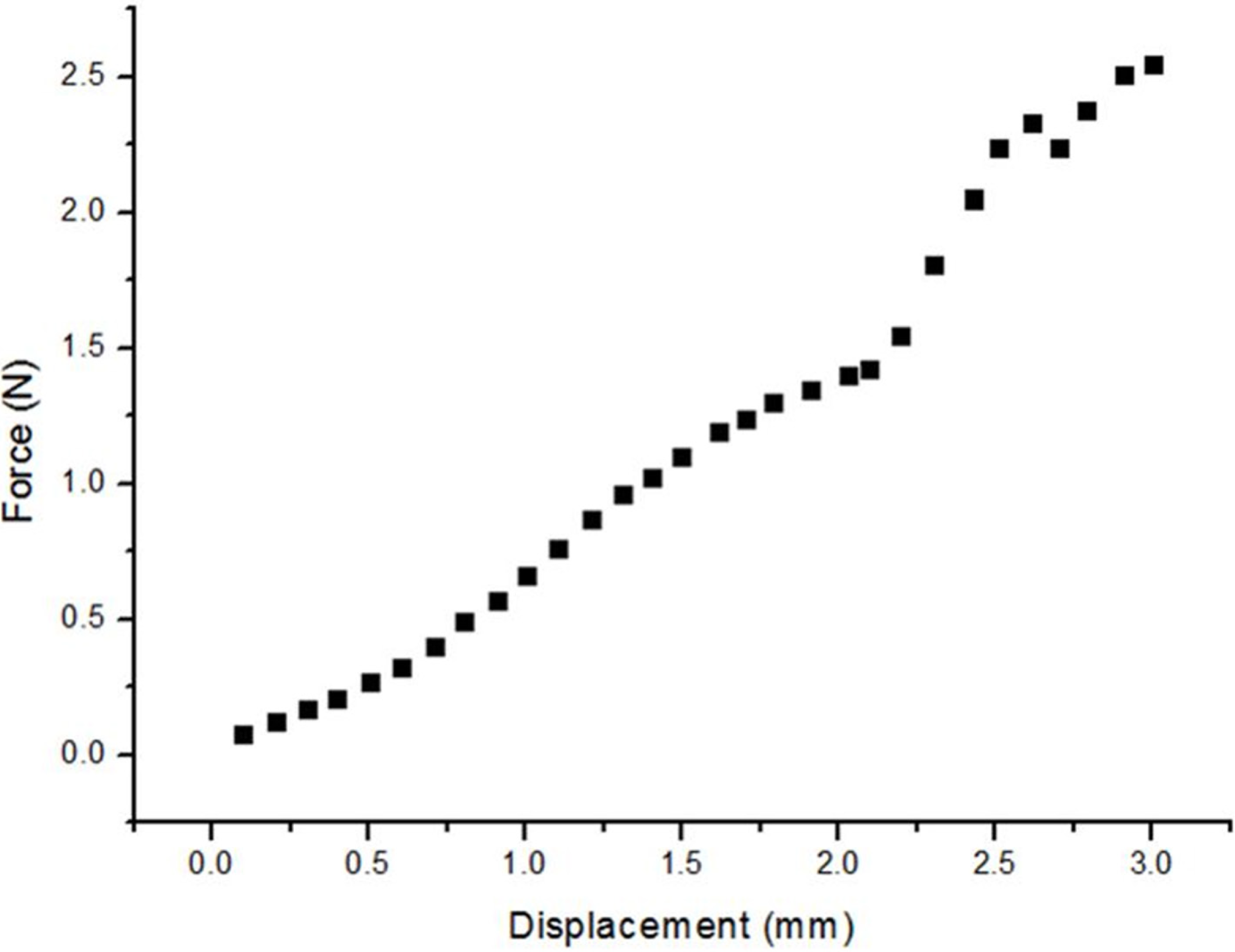
3.3. Penetrating Force

For easy insertion, a low penetrating force is desired. The penetrating force of the device can be calculated from a single needle’s penetrating force, which is measured by a force measurement instrument. Figure 8 shows the relationship between force and displacement. It can be seen that the force is increased along with the displacement. In the PDMS region (0 < displacement < 2 mm), the penetrating force increased linearly with the displacement. The drag coefficient can be calculated as 0.65 N/mm from this curve. When the needle plug is inserted into the steel nets (2 mm < displacement < 2.5 mm), the force obviously increases and arrived at about 1.2 N. The reason is the increasing friction force caused by the interference in the fit between needle plug and nets. Then the total penetrating force of the device with two needles can be calculated by following equation:
F = 2(at + b)
where F and t represent the total penetrating force and the total thickness of PDMS, respectively. a and b are the drag coefficient and interference fit force, respectively. Because a is 0.65 N/mm, b is 1.2 N, and t is 3 mm (the thickness of the designed of socket = 3 mm), the maximum penetrating force can be calculated as about 6 N.
Figure 8. The relationship between force and displacement.
Micromachines 06 00396 g008

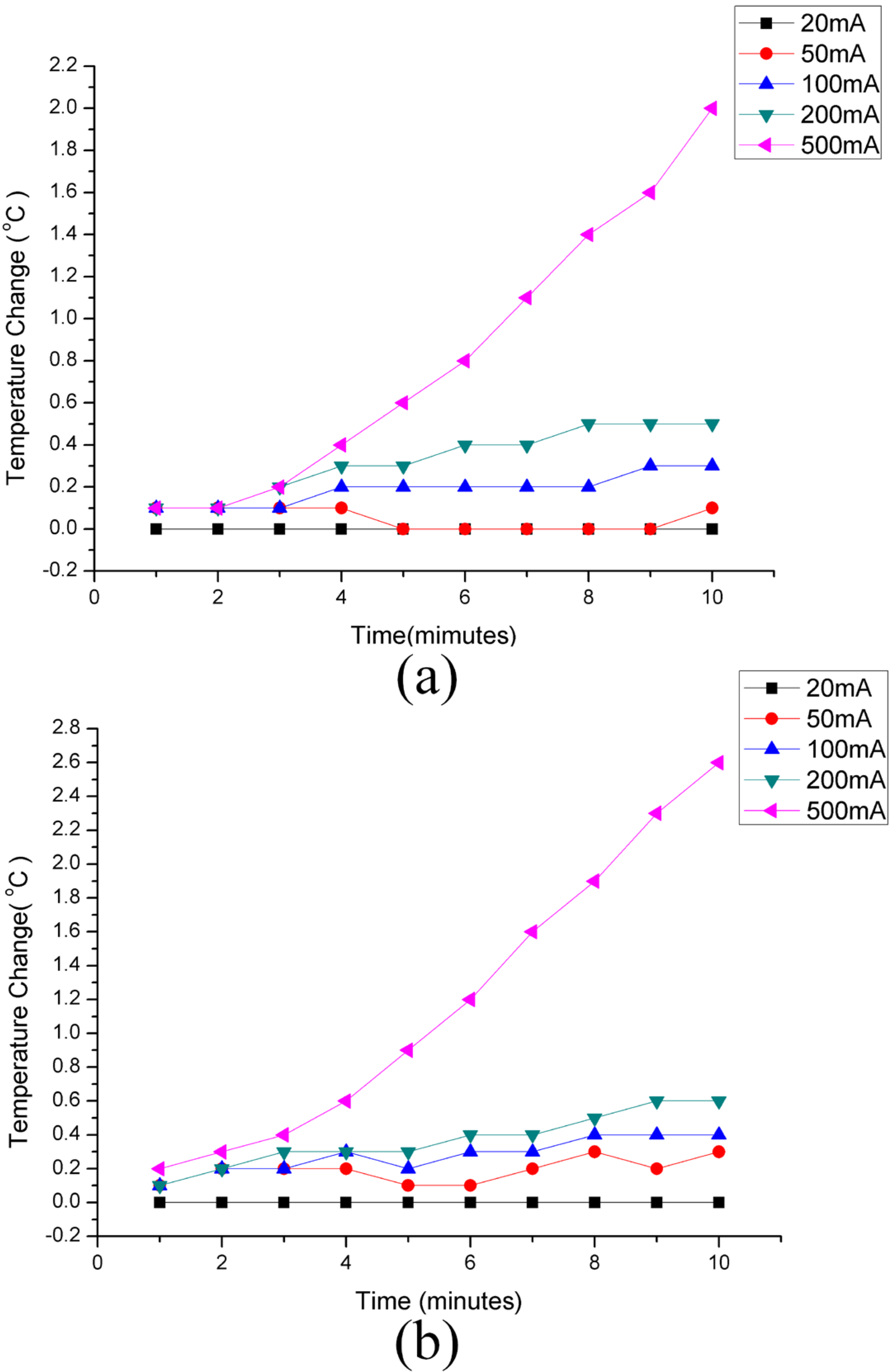
3.4. Charging Temperature

High charging temperature will burn the skin and tissue during power transfer process. In order to measure the charging temperature, the 1.2 V NiMH AA battery was recharged by different current levels at room temperature under a constant current power supply. Then, the temperature of the needles were measured by two thermometers at the same time. Figure 9 shows the temperature changes of the two needles under different recharging currents. The device was fully immersed in 0.9% NaCl solution with a base temperature of 26.8 °C under different recharging current levels. Since the electrical nets were encapsulated in PDMS, the dissipating speed of heat is slower compared to the notch part of the needles. This is the main reason for the rapid temperature changes under large charging currents. Thus, the design of the notch part of the needles is helping to cool the needles with the air around them. Normally, this has little effect when the charging currents is between 20 and 100 mA. However, it could help reduce the temperature change by 0.1 and 0.3 °C when the currents wee 200 and 500 mA compared to the non-notched devices, respectively. It can be seen that the charging current between 20 and 200 mA makes little temperature change. When the charging current increased to 500 mA, a dramatic increase of temperature occurred. This suggested that 200 mA recharging current would be recommended during power transfer process. It took 2.1 h to fully charge the battery under a 200 mA charging current. The local temperature rose about 0.56 °C after a full charge. Practically, the charging process could be divided into several sections to reduce the temperature changes.
Figure 9. The temperature changes of two needles under different recharging current levels with base a temperature of 26.8 °C. (a) The temperature changes of Needle one. (b) The temperature changes of Needle two.
Micromachines 06 00396 g009

3.5. Implantation of Device

Figure 10 shows the implantation of device in pork tissue. Two green litz wires were connected with the anode and cathode, respectively. When the plug is inserted into the socket through the skin, the anode and cathode of the battery contacts the terminals of the plug. In the experiment, a 1.2 V NiMH AA battery was used to connect the green lead wires. Then, the multimeter was used to measure the potential from the terminals after the plug is inserted into the socket. The measured 1.2 V potential demonstrated effectiveness of electrical connection of the device in implantation occasions. Figure 10b shows the picture of the socket implanted in pork tissue by ultrasound imaging.
Figure 10. The implantation of device in pork tissue. (a) The picture of the device implanted in pork tissue. (b) The picture of the device implanted in pork tissue by ultrasound imaging.
Micromachines 06 00396 g010

4. Conclusions

In this paper, a transdermal power transfer device for implantable applications was successfully fabricated. The interference fit between needles and stainless steel nets realized the reliable electrical connection and good maneuverability during power transfer process. PDMS encapsulation shell with a number of punctures on it showed good waterproofness for preventing tissue fluid infiltration. Furthermore, the low insertion force demonstrated easy insertion of the needle plug. Moreover, the little changes of charging temperature under 200 mA also indicated safe recharging. These characteristics were all desired in charging process. This transdermal power recharging system will be suitable for implantable applications.

Acknowledgments

This work is partly supported by the National Natural Science Foundation of China (No. 51475307, 61176104), 973 Program (2013CB329401), Shanghai Municipal Science and Technology Commission (No.13511500200), Specialized Research Fund for the Doctoral Program of Higher Education (20130073110087), National Defense Pre-Research Foundation of China (No. 9140A26060313JW3385), Human Factor Key Lab (HF2012-k-01), SJTU-Funding (YG2012MS51). The authors are also grateful to the colleagues for their essential contribution to this work.

Author Contributions

Jing-Quan Liu designed the devices and the experiments, wrote large parts of the manuscript, authored almost all of the illustrations and edited the article as a whole. Yue-Feng Rui performed the microfabrication, Xiao-Yang Kang was responsible for designing and performing the electrochemical measurements, Bin Yang helped the random insertion experiment, Xiang Chen helped PDMS encapsulation shell and Chun-Sheng Yang helped the implantation of device in pork tissue.

Conflicts of Interest

The authors declare no conflict of interest.

References

  1. Gamini, D.S.; Shastry, P.N. Design and measurements of implantable chip radiator and external receptor for wireless blood pressure monitoring system. In Proceedings of IEEE 2009 MTT-S International Microwave Symposium Digest, Boston, MA, USA, 7–12 June 2009; pp. 1681–1684.
  2. Hao, S.Y.; Taylor, J.; Miles, A.W.; Bowen, C.R. An implantable electronic system for in-vivo stability evaluation of prosthesis in total hip and knee arthroplasty. In Proceedings of IEEE 2009 Instrumentation and Measurement Technology Conference, Singapore, 5–7 May 2009; pp. 167–172.
  3. Ko, W.H.; Guo, J.; Ye, X.S.; Zhang, R.; Young, D.J.; Megerian, C.A. Mems acoustic sensors for totally implantable hearing aid systems. In Proceedings of IEEE 2008 International Symposium on Circuits and Systems (ISCAS 2008), Seattle, WA, USA, 18–21 May 2008; pp. 1812–1817.
  4. Rahimi, S.; Sarraf, E.H.; Wong, G.K.; Takahata, K. Implantable drug delivery device using frequency-controlled wireless hydrogel microvalves. Biomed. Microdevices 2011, 13, 267–277. [Google Scholar] [CrossRef] [PubMed]
  5. Winzenburg, G.; Schmidt, C.; Fuchs, S.; Kissel, T. Biodegradable polymers and their potential use in parenteral veterinary drug delivery systems. Adv. Drug Deliv. Rev. 2004, 56, 1453–1466. [Google Scholar] [CrossRef] [PubMed]
  6. Chen, J.; Chu, M.; Koulajian, K.; Wu, X.Y.; Giacca, A.; Sun, Y. A monolithic polymeric microdevice for pH-responsive drug delivery. Biomed. Microdevices 2009, 11, 1251–1257. [Google Scholar] [CrossRef] [PubMed]
  7. Grider, J.S.; Brown, R.E.; Colclough, G.W. Perioperative management of patients with an intrathecal drug delivery system for chronic pain. Anesth. Analg. 2008, 107, 1393–1396. [Google Scholar] [CrossRef] [PubMed]
  8. Meacham, K.W.; Giuly, R.J.; Guo, L.; Hochman, S.; DeWeerth, S.P. A lithographically-patterned, elastic multi-electrode array for surface stimulation of the spinal cord. Biomed. Microdevices 2008, 10, 259–269. [Google Scholar] [CrossRef] [PubMed]
  9. McCreery, D.B. Cochlear nucleus auditory prostheses. Hear. Res. 2008, 242, 64–73. [Google Scholar] [CrossRef] [PubMed]
  10. Fayad, J.N.; Otto, S.R.; Shannon, R.V.; Brackmann, D.E. Cochlear and brainstern auditory prostheses “neural interface for hearing restoration: Cochlear and brain stem implants”. Proc. IEEE 2008, 96, 1085–1095. [Google Scholar] [CrossRef]
  11. Koo, K.I.; Lee, S.; Bae, S.H.; Seo, J.M.; Chung, H.; Cho, D.I. Arrowhead-shaped microelectrodes fabricated on a flexible substrate for enhancing the spherical conformity of retinal prostheses. J. Microelectromech. Syst. 2011, 20, 251–259. [Google Scholar] [CrossRef]
  12. Chandrakasan, A.P.; Verma, N.; Daly, D.C. Ultralow-power electronics for biomedical applications. Annu. Rev. Biomed. Eng. 2008, 10, 247–274. [Google Scholar] [CrossRef] [PubMed]
  13. Zhang, J.; Suo, Y.M.; Mitra, S.; Chin, S.; Hsiao, S.; Yazicioglu, R.F.; Tran, T.D.; Etienne-Cummings, R. An efficient and compact compressed sensing microsystem for implantable neural recordings. IEEE Trans. Biomed. Circuits Syst. 2014, 8, 485–496. [Google Scholar] [CrossRef] [PubMed]
  14. Park, S.; Borton, D.A.; Kang, M.Y.; Nurmikko, A.V.; Song, Y.K. An implantable neural sensing microsystem with fiber-optic data transmission and power delivery. Sensors 2013, 13, 6014–6031. [Google Scholar] [CrossRef] [PubMed]
  15. Chang, C.W.; Chiou, J.C. A wireless and batteryless microsystem with implantable grid electrode/3-dimensional probe array for ecog and extracellular neural recording in rats. Sensors 2013, 13, 4624–4639. [Google Scholar] [CrossRef] [PubMed]
  16. Cheong, J.H.; Ng, S.S.Y.; Liu, X.; Xue, R.F.; Lim, H.J.; Khannur, P.B.; Chan, K.L.; Lee, A.A.; Kang, K.; Lim, L.S.; et al. An inductively powered implantable blood flow sensor microsystem for vascular grafts. IEEE Trans. BioMed. Eng. 2012, 59, 2466–2475. [Google Scholar] [CrossRef]
  17. Mallela, V.S.; Ilankumaran, V.; Rao, N.S. Trends in cardiac pacemaker batteries. Indian Pacing Electrophysiol. J. 2004, 4, 201–212. [Google Scholar] [PubMed]
  18. Cong, P.; Suster, M.A.; Chaimanonart, N.; Young, D.J. Wireless power recharging for implantable bladder pressure sensor. In Proceedings of 2009 IEEE Sensors, Christchurch, New Zealand, 25–28 October 2009; pp. 1670–1673.
  19. Gaddam, V.R.; Yernagula, J.; Anantha, R.R.; Kona, S.; Kopparthi, S.; Chamakura, A.; Ajmera, P.K.; Srivastava, A. Remote power delivery for hybrid integrated bio-implantable electrical stimulation system. Proc. SPIE 2005, 5763, 20–31. [Google Scholar]
  20. Li, P.F.; Bashirullah, R.; Principe, J.C. A low power battery management system for rechargeable wireless implantable electronics. In Proceedings of 2006 IEEE International Symposium on Circuits and Systems, 2006, ISCAS 2006, Island of Kos, Greece, 21–24 May 2006; pp. 1139–1142.
  21. Evans, A.T.; Chiravuri, S.; Gianchandani, Y.B. Transdermal power transfer for recharging implanted drug delivery devices via the refill port. Biomed. Microdevices 2010, 12, 179–185. [Google Scholar] [CrossRef] [PubMed]
  22. Cong, P.; Chaimanonart, N.; Ko, W.H.; Young, D.J. A wireless and batteryless 10-bit implantable blood pressure sensing microsystem with adaptive RF powering for real-time laboratory mice monitoring. IEEE J. Solid-State Circuits 2009, 44, 3631–3644. [Google Scholar] [CrossRef]
  23. Cong, P.; Ko, W.H.; Young, D.J. Wireless implantable blood pressure sensing microsystem design for monitoring of small laboratory animals. Sens. Mater. 2008, 20, 327–340. [Google Scholar]
  24. Cong, P.; Ko, W.H.; Young, D.J. Integrated electronic system design for an implantable wireless batteryless blood pressure sensing microsystem. IEEE Commun. Mag. 2010, 48, 98–104. [Google Scholar] [CrossRef]
  25. Cong, P.; Ko, W.H.; Young, D.J. Wireless batteryless implantable blood pressure monitoring microsystem for small laboratory animals. IEEE Sens. J. 2010, 10, 243–254. [Google Scholar] [CrossRef]
  26. Gosselin, B.; Simard, V.; Sawan, M. Low-power implantable microsystem intended to multichannel cortical recording. IEEE Int. Symp. Circuits Syst. 2004, 4, 5–8. [Google Scholar] [CrossRef]
  27. Martelli, D.; Silvani, A.; McAllen, R.M.; May, C.N.; Ramchandra, R. The low frequency power of heart rate variability is neither a measure of cardiac sympathetic tone nor of baroreflex sensitivity. Am. J. Physiol. Heart. Circ. Physiol. 2014, 307. [Google Scholar] [CrossRef]
  28. Huang, S.C.; Wong, M.K.; Lin, P.J.; Tsai, F.C.; Fu, T.C.; Wen, M.S.; Kuo, C.T.; Wang, J.S. Modified high-intensity interval training increases peak cardiac power output in patients with heart failure. Eur. J. Appl. Physiol. 2014, 114, 1853–1862. [Google Scholar] [CrossRef] [PubMed]
  29. Grodin, J.L.; Dupont, M.; Mullens, W.; Taylor, D.O.; Starling, R.C.; Tang, W. The prognostic role of cardiac power indices in advanced chronic heart failure. J. Heart Lung Transpl. 2014, 33. [Google Scholar] [CrossRef]
  30. Mun, J.Y.; Seo, M.G.; Kang, W.G.; Jun, H.Y.; Park, Y.H.; Pack, J.K. Study on the human effect of a wireless power transfer device at low frequency. In Proceedings of 2012 Progress in Electromagnetics Research Symposium (PIERS 2012), Moscow, Russia, 19–23 August 2012; pp. 322–324.
  31. Leung, H.Y.; Budgett, D.M.; Taberner, A.; Hu, P. Power loss measurement of implantable wireless power transfer components using a peltier device balance calorimeter. Meas. Sci. Technol. 2014, 25. [Google Scholar] [CrossRef]
  32. Shmilovitz, D.; Ozeri, S.; Wang, C.C.; Spivak, B. Noninvasive control of the power transferred to an implanted device by an ultrasonic transcutaneous energy transfer link. IEEE Trans. BioMed. Eng. 2014, 61, 995–1004. [Google Scholar] [CrossRef] [PubMed]
  33. Wang, J.X.; Wang, X.P.; Ma, Y.J.; Liu, N.; Yang, Z.Y. Analysis of heat transfer in power split device for hybrid electric vehicle using thermal network method. Adv. Mech. Eng. 2014, 2014, 210170. [Google Scholar] [CrossRef]
  34. Jonah, O.; Georgakopoulos, S.V.; Tentzeris, M.M. Wireless power transfer to mobile wearable device via resonance magnetic. In Proceedings of IEEE 14th Annual Wireless and Microwave Technology Conference (WAMICON), Orlando, FL, USA, 7–9 April 2013; pp. 1–3.
  35. Krop, D.C.J.; Jansen, J.W.; Lomonova, E.A. Decoupled modeling in a multifrequency domain: Integration of actuation and power transfer in one device. IEEE Trans. Magn. 2013, 49, 3009–3019. [Google Scholar] [CrossRef]
  36. Van Mastrigt, R.; de Zeeuw, S.; Boeve, E.R.; Groen, J. Diagnostic power of the noninvasive condom catheter method in patients eligible for transurethral resection of the prostate. Neurourol. Urodynam. 2014, 33, 408–413. [Google Scholar]
  37. Myers, K.A.; Leung, M.T.; Potts, M.T.; Potts, J.E.; Sandor, G.G.S. Noninvasive assessment of vascular function and hydraulic power and efficiency in pediatric fontan patients. J. Am. Soc. Echocardiog. 2013, 26, 1221–1227. [Google Scholar] [CrossRef]
  38. Suzuki, S.; Ishihara, M.; Kobayashi, Y. The improvement of the noninvasive power-supply system using magnetic coupling for medical implants. IEEE Trans. Magn. 2011, 47, 2811–2814. [Google Scholar] [CrossRef]
  39. Li, Q.B.; Liu, J.Q.; Zhang, G.J. Research on continuum power regression in noninvasive measurement of human blood glucose. Spectrosc. Spect. Anal. 2011, 31, 1481–1485. [Google Scholar]
  40. Rodger, D.C.; Fong, A.J.; Wen, L.; Ameri, H.; Ahuja, A.K.; Gutierrez, C.; Lavrov, I.; Hui, Z.; Menon, P.R.; Meng, E.; et al. Flexible parylene-based multielectrode array technology for high-density neural stimulation and recording. Sens. Actuat. B Chem. 2008, 132, 449–460. [Google Scholar] [CrossRef]
  41. Wei, P.; Taylor, R.; Ding, Z.; Chung, C.; Abilez, O.J.; Higgs, G.; Pruitt, B.L.; Ziaie, B. Stretchable microelectrode array using room-temperature liquid alloy interconnects. J. Micromech. Microeng. 2011, 21. [Google Scholar] [CrossRef]
  42. Rui, Y.F.; Liu, J.Q.; Yang, B.; Li, K.Y.; Yang, C.S. Parylene-based implantable platinum-black coated wire microelectrode for orbicularis oculi muscle electrical stimulation. Biomed. Microdevices 2012, 14, 367–373. [Google Scholar] [CrossRef] [PubMed]

