Article

Ultrasonic Spray-Coating of Large-Scale TiO2 Compact Layer for Efficient Flexible Perovskite Solar Cells

1
State Key Laboratory of Advanced Technology for Materials Synthesis and Processing, Wuhan University of Technology, Wuhan 430070, China
2
Hubei Key Laboratory of Low Dimensional Optoelectronic Materials and Devices, Hubei University of Arts and Science, Xiangyang 441053, China
3
School of Automotive Engineering, Wuhan University of Technology, Wuhan 430070, China
*
Authors to whom correspondence should be addressed.
Micromachines 2017, 8(2), 55; https://doi.org/10.3390/mi8020055
Submission received: 31 December 2016 / Revised: 23 January 2017 / Accepted: 26 January 2017 / Published: 14 February 2017
(This article belongs to the Special Issue Flexible and Stretchable Electronics)

Abstract

:
Flexible electronics have attracted great interest in applications for the wearable devices. Flexible solar cells can be integrated into the flexible electronics as the power source for the wearable devices. In this work, an ultrasonic spray-coating method was employed to deposit TiO2 nanoparticles on polymer substrates for the fabrication of flexible perovskite solar cells (PSCs). Pre-synthesized TiO2 nanoparticles were first dispersed in ethanol to prepare the precursor solutions with different concentrations (0.5 mg/mL, 1.0 mg/mL, 2.0 mg/mL) and then sprayed onto the conductive substrates to produce compact TiO2 films with different thicknesses (from 30 nm to 150 nm). The effect of the different drying processes on the quality of the compact TiO2 film was studied. In order to further improve the film quality, titanium diisopropoxide bis(acetylacetonate) (TAA) was added into the TiO2-ethanol solution at a mole ratio of 1.0 mol % with respect to the TiO2 content. The final prepared PSC devices showed a power conversion efficiency (PCE) of 14.32% based on the indium doped tin oxide coated glass (ITO-glass) substrate and 10.87% on the indium doped tin oxide coated polyethylene naphthalate (ITO-PEN) flexible substrate.

1. Introduction

With the global energy consumption increasing, cheap, green and environmentally friendly energy sources are in urgent demand due to the reduction of fossil fuels. Photovoltaic technology is an ideal solution to alleviate the energy crisis and environmental pollution problems. Organic-inorganic lead halide perovskite solar cells (PSCs) have attracted great interest due to their rapid increase in power conversion efficiencies (PCE) from 3.8% to 22.1% within only seven years [1,2,3]. These great improvements are mainly attributed to the excellent photo-electronic properties of perovskite materials, such as high light absorption properties, direct bandgaps, high charge-carrier mobility and a long electron–hole exciton transport distance (more than 1 μm) [4,5,6]. Compared to the commercial silicon-based solar cells, PSCs show great advantages with a simplified architecture and a low-cost solution-processed technology, which give them great potential for the future photovoltaic industry [7].
Organic-inorganic lead halide perovskite (CH3NH3PbI3) was first used as a sensitizer in dye-sensitized solar cells (DSSCs) by Kojima in 2009 [8] with a PCE of 3.8%, but the performance decreased rapidly due to the dissolution of the perovskite in the liquid electrolytes. Two years later, the solid-state hole-transporting material 2,2′,7,7′-tetrakis-(N,N-di-p-methoxypheny-lamine) 9,9′-spirobifluorene (spiro-OMeTAD) was introduced by Park and Grätzel, and achieved a reported PCE of 9.7% [9]. Since the all solid-state-type PSCs were fabricated, the photo-electronic performance improved rapidly with the use of different electronic/hole transporting semi-conductive materials, such as TiO2, ZnO, SnO, PCBM, P3HT, etc. [10]. Depending on the different architectures, the PSCs can be generally classified into mesoscopic, meso-superstructured and planar heterojunction types [11]. Among these types, the planar PSCs have a simplified architecture and are easily produced by a solution process. In a planar solar cell, the photoactive layer, CH3NH3PbI3, is sandwiched between an electron-transporting layer (ETL) and a hole-transporting layer (HTL), which is suitable for large-scale commercial manufacturing layer-by-layer. The ETL plays an important role as it allows the transport of electrons while blocking the holes. Thus, it influences the carriers’ injection, collection, transportation, recombination, and then the overall performance of the PSCs [12]. Anatase TiO2 is the most widely used ETL for planar PSCs, but it still requires a high temperature sintering of the TiO2 compact layer to achieve a high efficiency. In general, this compact layer is prepared by spin-coating or spray pyrolysis of a TiO2 precursor solution with subsequent sintering at 500 °C to transform the amorphous oxide layer into the crystalline phase (anatase), which provides good charge transport properties [13]. The involvement of the high temperature sintering process of TiO2 has limited the development of flexible PSCs fabricated on plastic substrates, such as polyethylene terephthalate (PET) and polyethylene naphthalate (PEN).
Since the first flexible perovskite solar cell was reported [14], more efforts have been devoted to it and have achieved efficiencies of over 10% on polymer substrates [15,16], demonstrating that efficient perovskite solar cells can be fabricated at low temperatures with a “regular” design. Atomic layer deposition [17,18], microwave sintering [19] and inductively coupled plasma (ICP)-assisted DC magnetron sputtering [20] have been used for deposition of the TiO2 compact layer at low temperatures. A photonic-cured compact TiO2 layer has been used on a PET substrate with a high efficiency of 11.2% by Xiao [21]. Snaith et al. realized flexible PSC with an efficiency of 15.9% on a low-temperature processed TiO2 compact layer by spin-coating the TiO2 precursor on fluorine doped tin oxide coated glass (FTO-glass) [22]. Yang et al. developed a process to fabricate a very dense amorphous TiO2 using DC magnetron sputtering at room temperature and achieved 15.07% PCE based on a flexible PET substrate [23]. Sanjib et al. used a combination of ultrasonic spray-coating and a low-thermal-budget photonic curing technology for the first time to fabricate a flexible PSC with an efficiency of 8.1% [24]. Supasai et al. fabricated compact layers of crystalline TiO2 thin films using aerosol spray pyrolysis on FTO-glass for PSCs, achieving the best efficiency of 6.24% [25]. Kim et al. fabricated a mesoporous TiO2 ETL with a large area of 10 cm × 10 cm using electro-spray deposition (ESD) for the first time, which resulted in an optimized PCE of 15.11%, higher than that (13.67%) of the PSC with spin-coated TiO2 films [26]. Both the aerosol spraying and ESD methods demonstrated great potential in the large-scale fabrication of PSCs. However, the TiO2 films deposited by the above two spraying methods require high temperature sintering, which is not suitable for the preparation of flexible PSCs. The use of these technologies has allowed for the development of all-low-temperature processed PSCs on flexible substrates, but at the same time, has made the process more complicated, resulting in the increase of the manufacturing cost.
Here, we report a low temperature fabrication (<150 °C) of a compact layer composed of highly crystalline small nanoparticles of anatase TiO2 (diameter <10 nm) dispersed in ethanol. The ultrasonic spray-coating method was employed for the deposition of the TiO2 compact layer, demonstrating the capability to precisely and reliably deposit thin and uniform layers. Various parameters have to be considered in the process of ultrasonic spraying, such as the flow rate of the TiO2 ethanol solution, the gas flow pressure which carries the sprayed droplets to the substrate, the distance between the spray nozzle and the substrate, as well as the moving speed of the nozzle during spraying [27,28]. Through the optimization of these parameters, two technological regimes named “wet-film” (w-film) and “dry-film” (d-film) are compared in our work. The former approach results in a dense TiO2 layer of different thicknesses (30 nm to 150 nm) by changing the concentration of the dispersion. In addition, a small amount of titanium diisopropoxide bis(acetylaceto-nate) (TAA) (1.0 mol % with respect to the TiO2 content) is added to the colloidal TiO2 dispersion, resulting in the highest PCE of 14.32% based on ITO-glass and 10.87% based on ITO-PEN, both with an active area of 0.4 cm × 0.4 cm. Through the same method, a large-area flexible PSC of 5 cm × 5 cm is fabricated.

2. Materials and Methods

2.1. Materials

Unless specified otherwise, all the chemicals were purchased from either Alfa Aesar or Sigma-Aldrich and used as received. 2,2′,7,7′-tetrakis-(N,N-di-p-methoxypheny-lamine) 9,9′-spirobifluorene (spiro-OMeTAD) was purchased from Shenzhen Feiming Science and Technology Co., Ltd. (Shenzhen, China), and MAI (CH3NH3I) was purchased from Lumtec, Taiwan.

2.2. Substrates

Indium doped tin oxide coated glass (ITO-Glass) and polyethylene naphthalate (ITO-PEN) were etched by zinc powder and hydrochloric acid, then followed by ultrasonic cleaning in detergent, pure water and ethanol for 15 min, respectively. The substrate (ITO-Glass or ITO-PEN) was cut into suitable size and plasma cleaned for 5 min to remove any organic material on the surface. Especially, the flexible ITO-PEN substrate was mounted onto glass micro-slides before using.

2.3. Synthesis of TiO2 Nanoparticles

The anatase titanium oxide nanoparticles were synthesized according to previously reported method published elsewhere [29]. Briefly, 0.5 mL of anhydrous TiCl4 (99.9%, Aladdin, Shanghai, China) was added dropwise into 2 mL of anhydrous ethanol (Sigma-Aldrich, Shanghai, China), stirring for 5 min till the mixed yellow liquid was cooled down to room temperature. Then the whole content was transferred into a vial containing 10 mL anhydrous benzyl alcohol (Aladdin, Shanghai, China), with the color of the clear solution changing to light yellow. The solution was heated to 80 °C and reacted for 9 h. After the reaction the solution was cooled down to the room temperature, and a translucent dispersion of very fine TiO2 nanoparticles was obtained. Then add 36 mL of diethyl ether to 4 mL of the above solution to precipitate the TiO2 which was centrifuged at 4000 rpm for 5 min, washed with ethanol and diethyl ether. The above steps were repeated three times and the final precipitation was redispersed in 10 mL of anhydrous ethanol, resulting in a colloidal solution of approximately 12 mg TiO2/mL ethanol but easily aggregated. The TiO2 ethanol solution was further diluted into 0.5 mg/mL, 1.0 mg/mL and 2.0 mg/mL respectively for the late ultrasonic spraying. In order to disperse the TiO2 nanoparticles and enhance the adhesion as well as the connection between nanoparticles, a small amount of TAA was added into the diluted dispersion with a mole ratio of 1.0 mol %, 2.0 mol % and 3.0 mol % respectively. The solution was left to stand for at least 2 h before spraying, but could be stable for months.

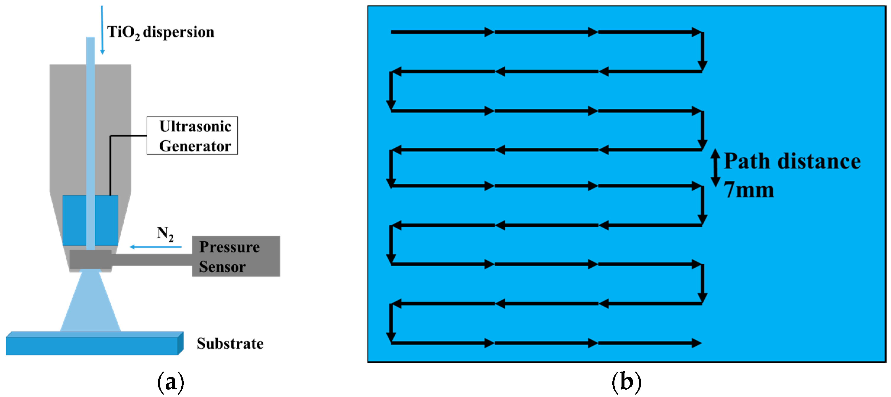
2.4. Deposition of the TiO2 Compact Layer

The low-temperature processed TiO2 compact layer was deposited by ultrasonic spraying the colloidal dispersion of anatase particles in anhydrous ethanol, formulated with TAA, followed by treating at 135 °C for 1 h to remove ethanol solvent. Figure 1a shows the schematic representation of setup for the spray coating. Figure 1b showed the spray nozzle moving path during the spray. Spray coating was carried out in an Exacta Coat Ultrasonic Spraying System (Sono-Tek Corpration, Milton, NY, USA) equipped with an AccuMist nozzle. The thickness of the compact layer was tuned by the concentration of TiO2 nanoparticles (0.5–2.0 mg/mL).

2.5. Device Fabrication

After deposition of the TiO2 compact layer, the substrate with appropriate size (1.5 cm × 1.5 cm for small devices and 5.0 cm × 5.0 cm for large area devices) was transferred into a N2 filled glove box. The perovskite and hole conductor solutions were prepared in a N2 glove box before deposition. The perovskite was deposited by spin coating 25 μL of a 1.25 mol/L solution of CH3NH3I and PbI2 (molar ratio 1:1) in DMF at 6500 rpm for 30 s using the gas-assisted method [30], meanwhile a 60 psi dry N2 gas stream was blown onto the film for 8 s from the third second of spinning. For the fabrication of flexible devices with large area, 200 μL perovskite solution was coated on TiO2 compact layer and spin-coated at 5000 rpm for 30 s, followed by dropping 200 μL chlorobenzene (CBZ) at the fifth second of spinning. The films were subsequently annealed on a hot plate at 100 °C for 10 min in the glove box. After letting the films cool for 5 min, 20 μL spiro-OMeTAD/CBZ solution (68 mM spiro-OMeTAD, 150 mM tert-butylpyridine and 25 mM lithium bis(tri-fluoromethanesulphonyl)imide) was spin-coated at 3000 rpm for 30 s. Promptly after the hole transport material deposition, a gold counter electrode (60 nm) was evaporated under high vacuum to complete the device.

2.6. Characterizations

The morphologies and microstructures of the prepared low-temperature processed TiO2 compact and the cross-sectional structure of the perovskite solar cells were investigated using a field-emission scanning electron microscopy (FE-SEM, Zeiss Ultra Plus). To examine the surface roughness, the films were characterized by BY2000 atomic force microscopy (AFM). The TiO2 anatase phase was tested by an X-ray diffractometer (XRD, D8 Advance). The photocurrent density-voltage curves of the PSCs were measured using a solar simulator (Oriel 94023A, 300 W). The intensity (100 mW/cm2) was calibrated using a standard Si-solar cell (Oriel, VLSI standards). All the devices were tested under AM 1.5 G sun light (100 mW/cm2) using a metal mask of 0.16 cm2 with a scan rate of 0.01 V/s. Some parameters would be mentioned to evaluate the performance of PSCs, such as open circuit voltage (Voc), short circuit current (Jsc), fill fact (FF), and power conversion efficiency (PCE).

3. Results and Discussion

Anatase-type TiO2 nanoparticles were synthesized through a method published elsewhere [29], using titanium tetrachloride (TiCl4) as the precursor, and anhydrous ethanol and benzyl alcohol as solvents. The TiO2 nanoparticles synthesized via this method are highly crystalline, shown in Figure 2a,b. In the XRD pattern of the TiO2 powder prepared by drying the as-synthesized nanoparticles at 135 °C to evaporate the ethanol solvent, three typical diffraction peaks occur at 25.5°, 38.5° and 48°, which respectively belong to the (101), (004) and (200) planes of the anatase TiO2 crystal. The as-synthesized TiO2 nanoparticles could easily be dispersed in ethanol, which can be used for ultrasonic spraying directly. After the deposition of the TiO2 layer, the films had to be treated at 135 °C for 1 h, replacing the high-temperature sintering process. The size of the TiO2 nanoparticles was around 5 nm, as shown in the TEM image (Figure 2a), which can also be calculated by the Scherrer equation using the (101) diffraction peak through the formula reported elsewhere [31]. Figure 2c shows the XRD patterns of ITO-glass with/without the TiO2 layer, in which just a weak diffraction peak of TiO2 occurs at 25.5° due to the thin thickness of the TiO2 layer.
In order to obtain uniform and dense films of TiO2 compact layers, two technological regimes of ultrasonic spraying were built. During ultrasonic spraying, many parameters influence the uniformity, roughness, and coverage of the TiO2 film, such as the flow rate of the TiO2 ethanol solution, the gas flow pressure which carries the sprayed droplets to the substrate, the distance between the spray nozzle and the substrate, as well as the moving speed of the nozzle. The ultrasonic spraying technology was employed in the deposition of polymer films such as polyvinylpyrrolidone (PVP) by Sanjukta Bose et al. in 2013 [27]. Parts of the parameters have been discussed, resulting in uniform organic films with small roughness compared to the thickness of the films. Based on the work mentioned above, we optimized the process of spraying, and employed it to deposit inorganic TiO2 film. Figure 1a shows the schematic representation of the setup for the spray-coating. Figure 1b shows the ultrasonic spraying trajectory over the substrate. Snaith et al. realized low-temperature processed PSCs with power convention efficiencies (PCE) of up to 15.9% using a spin-coating method, demonstrating the optimum thickness of TiO2 to be approximately 45 nm [22], while the thickness of TiO2 prepared by high-temperature sintering at 500 °C is around 30 nm [7]. Based on these reports, we tuned the thickness of ultrasonic spraying TiO2 compact layer ranging from 30 nm to 100 nm by changing the spraying parameters and the concentration of the TiO2 ethanol solution.
During the spraying, two different technological regimes were termed “wet-film” (w-film) and “dry-film” (d-film), depending on the drying type of the ethanol solvent. The former regime means that the ethanol solvent evaporates after the droplets are sprayed onto the substrate, forming a very uniform thin liquid membrane layer before the ethanol evaporates. A few seconds later, the solvent begins to evaporate, resulting in a uniform thin compact layer of TiO2. The latter regime means that the processing of ethanol evaporation occurs mainly before the droplets are sprayed onto the substrate, without forming the liquid membrane. The TiO2 compact layer prepared by the former regime was influenced by the “coffee-ring” effect, which is described by Deegan et al. as the result of capillary flow [32], where liquid evaporates faster from the pinned contact line of a deposited solution and is replenished by additional liquid from inside; however, this did not happen in the latter regime. During the spraying of the w-film regime, the pressure of the N2 flow was set to 0.3 psi, the flow rate of solution was set to 1.2 mL/min, and the speed of the moving nozzle was set to 50 mm/s, which can result in a thin liquid membrane on the surface of the substrate before the solvent evaporates; during the d-film regime, the three parameters were respectively set to 1.0 psi, 0.3 mL/min, and 20 mm/s. Figure 3 showed the AFM surface images of the TiO2 compact layers by ultrasonic spraying using 1.0 mg/mL of the TiO2 (without TAA) ethanol solution. The TiO2 film prepared by the w-film regime presented a root-mean-square (RMS) surface roughness of around 3.3 nm, while it increased to 44.6 nm rapidly with the d-film regime. It was attributed to the big holes between the TiO2 nanoparticles prepared through the d-film regime. In the film of the d-film regime, the connection between the particles was so weak that big holes appeared because of the evaporation of ethanol before the droplets were deposited on the substrate. In addition, more spraying cycles were needed to obtain the optimum thickness of the TiO2 film through the d-film regime, which increased the roughness of film, while just one cycle was enough to achieve the thickness with the w-film regime. Thus, it is better to fabricate the TiO2 compact layer using the w-film regime.
In order to discuss the influence of the thickness of the ultrasonically sprayed TiO2 compact layer on the performance of PSC devices, ITO-glass substrates coated with TiO2 films of different thicknesses (30–100 nm) were made into complete planar PSC devices. The thickness of the TiO2 film was tuned by changing the concentration. Table 1 shows the photovoltaic parameters obtained from the current-voltage measurements of devices with different compact layers. It is obvious that the optimal concentration for the performance was 1.0 mg/mL, with a thickness around 60 nm. Figure 4 shows the surface image of different functional layers, and a dense TiO2 compact layer was obtained (Figure 4b). Each functional layer can be clearly distinguished in the cross-section scanning electron microscopy (SEM) image (Figure 4d). The clear interface between the TiO2 layer and perovskite layer confirmed that the TiO2 layer was not utilized as a mesoscopic scaffold. It can be concluded that the uniform TiO2 compact layer with low roughness is suitable for the preparation of perovskite (Figure 4c), and the optimal thickness ranges around 60 nm. Figure 5a shows the current-voltage curves of PSCs prepared with a TiO2 solution of 1.0 mg/mL using the w-film regime, with an average PCE of 10.79%, and the highest PCE of 11.23%.
In addition, more works have been done to improve the performance of TiO2 by adding a small amount of TAA (1.0 mol %, 2.0 mol %, 3.0 mol % with respect to the TiO2 content), with almost a negligible influence on the thickness of the TiO2 film. The solutions with different amounts of TAA were ultrasonically sprayed on the substrates but with a similar thickness of the TiO2 compact layers, around 60 nm. The RSM increased to 7.6 nm from 3.3 nm without a significant change of the roughness of the bare ITO after 1.0 mol % TAA was added to a TiO2 solution of 1.0 mg/mL (Figure 6). It was found that the RMS increased with the additional increase of TAA. Furthermore, the increasing size of the large aggregates on the surface of the TiO2 film was observed in the AFM images (Figure 6).
The devices with the highest performance were prepared based on the TiO2 compact layer sprayed using the TiO2 solution with 1.0 mol % of TAA. The highest PCE of 14.32% was achieved, with a Voc of 1.008 mV, a Jsc of 20.82 mA/cm2, and a FF of 68.3%. The improvement of the performance was attributed to the addition of TAA, which enhanced the connection of the TiO2 nanoparticles. However, the addition of TAA increased the roughness of the film, which had a negative influence on the preparation of the perovskite. It was also observed that the hysteresis of the PSCs increased with the addition of TAA (Figure 5). To study the stability of PSCs based on ultrasonically sprayed TiO2, a typical PSC on ITO-glass was placed in a N2-filled glove box for long-duration stability testing. The PSC showed a good stability, as shown in Figure 7. The PCE of the device increased after two days, which can be attributed to the increase of the FF, caused by the enhancement of the connection between the TiO2 particles and the oxidation of the Spiro-OMeTAD.
The optimized process of the ultrasonic spraying of 1.0 mg/mL TiO2 solution with an addition of 1.0 mol % TAA was employed to fabricate PSCs on the flexible ITO-PEN substrate. A photographic image of the flexible device with a large area of 5.0 cm × 5.0 cm is shown in Figure 8a. The best-performing cell exhibited an outstanding photovoltaic performance with a Voc of 945 mV, a Jsc of 20.68 mA/cm2, a FF of 55.6% and a PCE of 10.87%, tested under AM 1.5 G sunlight (100 mW/cm2) using a metal mask of 0.16 cm2 (Figure 8b), which offers great potential for flexible PSCs with a large area. Figure 9 shows the current-voltage curve of a flexible large-area PSC with an active area of 13.5 cm2, tested without a mask under standard sunlight. A PCE of 4.33% was achieved for the large-area flexible PSC.

4. Conclusions

In summary, using an ultrasonic spraying technology, we prepared a low-temperature processed TiO2 compact layer with low roughness compared to the thickness of the TiO2 film on both rigid and flexible substrates with a large area. Two different drying process-related regimes were studied. The spraying method of the w-film regime showed advantages in preparing low-temperature processed TiO2, resulting in a film with a RSM of 3.3 nm. A small amount of TAA was added into the TiO2 dispersion to enhance the connection of the particles, thus improving the performance of the PSCs. The best-performing device was achieved with a PCE of 14.32% based on ITO-glass, and a PCE of 10.87% based on ITO-PEN. This method provides a potential route for the fabrication of efficient large-area flexible PSCs.

Acknowledgments

This work is financially supported by the National Natural Science Foundation of China (NSFC 51672202) and the Fundamental Research Funds for the Central Universities (WUT: 2016IVA085). Hubei Key Laboratory of Low Dimensional Optoelectronic Materials and Devices at Hubei University of Arts and Science was acknowledged for the measurement of AFM. The Analytical and Testing Center of Wuhan University of Technology and the Wuhan National Laboratory for Optoelectronics are also acknowledged for the SEM and TEM characterizations.

Author Contributions

Fuzhi Huang, Juan Zhao, and Peng Zhou conceived and designed the experiments; Peng Zhou performed the experiments; Fuzhi Huang and Peng Zhou analyzed the data; Wangnan Li, Tianhui Li, Tongle Bu, Xueping Liu, Jing Li, Jiang He, Rui Chen and Kunpeng Li contributed characterizations; Peng Zhou wrote the paper.

Conflicts of Interest

The authors declare no conflict of interest.

References

  1. Park, N.G. Perovskite solar cells: An emerging photovoltaic technology. Mater. Today 2015, 18, 65–72. [Google Scholar] [CrossRef]
  2. Kim, H.S.; Im, S.H.; Park, N.G. Organolead halide perovskite: New horizons in solar cell research. J. Phys. Chem. C 2014, 118, 5615–5625. [Google Scholar] [CrossRef]
  3. Hodes, G. Perovskite-Based Solar Cells. Science 2013, 342, 317–318. [Google Scholar] [CrossRef] [PubMed]
  4. Bai, S.; Wu, Z.; Wu, X.; Jin, Y.; Zhao, N.; Chen, Z.; Mei, Q.; Wang, X.; Ye, Z.; Song, T.; et al. High-performance planar heterojunction perovskite solar cells: Preserving long charge carrier diffusion lengths and interfacial engineering. Nano Res. 2014, 7, 1749–1758. [Google Scholar] [CrossRef]
  5. Dong, Q.; Fang, Y.; Shao, Y.; Mulligan, P.; Qiu, J.; Cao, L.; Huang, J. Electron-hole diffusion lengths >175 μm in solution-grown CH3NH3PbI3 single crystals. Science 2015, 347, 967–970. [Google Scholar] [CrossRef] [PubMed]
  6. Stranks, S.D.; Eperon, G.E.; Grancini, G.; Menelaou, C.; Alcocer, M.J.P.; Leijtens, T.; Herz, L.M.; Petrozza, A.; Snaith, H.J. Electron-Hole Diffusion Lengths Exceeding 1 Micrometer in an Organometal Trihalide Perovskite Absorber. Science 2013, 342, 341–344. [Google Scholar] [CrossRef] [PubMed]
  7. Bu, T.; Wen, M.; Zou, H.; Wu, J.; Zhou, P.; Li, W.; Ku, Z.; Peng, Y.; Li, Q.; Huang, F.; et al. Humidity controlled sol-gel Zr/TiO2 with optimized band alignment for efficient planar perovskite solar cells. Sol. Energy 2016, 139, 290–296. [Google Scholar] [CrossRef]
  8. Kojima, A.; Teshima, K.; Shirai, Y.; Miyasaka, T. Organometal halide perovskites as visible-light sensitizers for photovoltaic cells. J. Am. Chem. Soc. 2009, 131, 6050–6051. [Google Scholar] [CrossRef] [PubMed]
  9. Kim, H.S.; Lee, C.R.; Im, J.H.; Lee, K.B.; Moehl, T.; Marchioro, A.; Moon, S.J.; Humphry-Baker, R.; Yum, J.H.; Moser, J.E.; et al. Lead iodide perovskite sensitized all-solid-state submicron thin film mesoscopic solar cell with efficiency exceeding 9%. Sci. Rep. 2012, 2, 591. [Google Scholar] [CrossRef] [PubMed]
  10. Mahmood, K.; Swain, B.S.; Jung, H.S. Controlling the surface nanostructure of ZnO and Al-doped ZnO thin films using electrostatic spraying for their application in 12% efficient perovskite solar cells. Nanoscale 2014, 6, 9127–9138. [Google Scholar] [CrossRef] [PubMed]
  11. Heo, J.H.; Song, D.H.; Han, H.J.; Kim, S.Y.; Kim, J.H.; Kim, D.; Shin, H.W.; Ahn, T.K.; Wolf, C.; Lee, T.W.; et al. Planar CH3NH3PbI3 perovskite solar cells with constant 17.2% average power conversion efficiency irrespective of the scan rate. Adv. Mater. 2015, 27, 3424–3430. [Google Scholar] [CrossRef] [PubMed]
  12. Yang, G.; Tao, H.; Qin, P.; Kw, W.; Fang, G. Recent progress in electron transport layers for efficient perovskite solar cells. J. Mater. Chem. A 2016, 4, 3970–3990. [Google Scholar] [CrossRef]
  13. Peng, B.; Jungmann, G.; Jager, C.; Haarer, D.; Schmidt, H.W.; Thelakkat, M. Systematic investigation of the role of compact TiO2 layer in solid state dye-sensitized TiO2 solar cells. Coord. Chem. Rev. 2004, 248, 1479–1489. [Google Scholar] [CrossRef]
  14. Kumar, M.H.; Yantara, N.; Dharahi, S.; Graetzel, M.; Mhaisalkar, S.; Boix, P.P.; Mathews, N. Flexible, low-temperature, solution processed ZnO-based perovskite solid state solar cells. Chem. Commun. 2013, 49, 11089–11091. [Google Scholar] [CrossRef] [PubMed]
  15. Liu, D.; Yang, J.; Kelly, T.L. Compact layer free perovskite solar cells with 13.5% efficiency. J. Am. Chem. Soc. 2014, 136, 17116–17122. [Google Scholar] [CrossRef] [PubMed]
  16. Kim, B.J.; Kim, D.H.; Lee, Y.Y.; Shin, H.W.; Han, G.S.; Hong, J.S.; Mahmood, K.; Ahn, T.K.; Joo, Y.C.; Hong, K.S.; et al. Highly efficient and bending durable perovskite solar cells: Toward a wearable power source. Energy Environ. Sci. 2015, 8, 916–921. [Google Scholar] [CrossRef]
  17. Jiang, C.Y.; Koh, W.L.; Leung, M.Y.; Chiam, S.Y.; Wu, J.S.; Zhang, J. Low temperature processing solid-state dye sensitized solar cells. Appl. Phys. Lett. 2012, 100, 113901. [Google Scholar] [CrossRef]
  18. Munoz-Rojas, D.; Sun, H.; Iza, D.C.; Weickert, J.; Chen, L.; Wang, H.; Schmidt-Mende, L.; MacManus-Driscoll, J.L. High-speed atmospheric atomic layer deposition of ultra thin amorphous TiO2 blocking layers at 100 °C for inverted bulk heterojunction solar cells. Prog. Photovolt. Res. Appl. 2013, 21, 393–400. [Google Scholar]
  19. Hart, J.N.; Menzies, D.; Cheng, Y.B.; Simon, G.P.; Spiccia, L. Microwave processing of TiO2 blocking layers for dye-sensitized solar cells. J. Sol-Gel Sci. Technol. 2006, 40, 45. [Google Scholar] [CrossRef]
  20. Kim, H.-J.; Jeon, J.-D.; Kim, D. Y.; Lee, J.-J.; Kwak, S.-Y. Improved performance of dye-sensitized solar cells with compact TiO2 blocking layer prepared using low-temperature reactive ICP-assisted DC magnetron sputtering. J. Ind. Eng. Chem. 2012, 18, 1807–1812. [Google Scholar] [CrossRef]
  21. Das, S.; Gu, G.; Joshi, P.C.; Yang, B.; Aytug, T.; Rouleau, C.M.; Geohegan, D.B.; Xiao, K. Low thermal budget, photonic-cured compact TiO2 layers for high-efficiency perovskite solar cells. J. Mater. Chem. A 2016, 4, 9685. [Google Scholar] [CrossRef]
  22. Wojciechowski, K.; Saliba, M.; Leijtens, T.; Abate, A.; Snaith, H.J. Sub-150 degrees C processed meso-superstructured perovskite solar cells with enhanced efficiency. Energy Environ. Sci. 2014, 7, 1142–1147. [Google Scholar] [CrossRef]
  23. Yang, D.; Yang, R.; Zhang, J.; Yang, Z.; Liu, S.; Li, C. High efficiency flexible perovskite solar cells using superior low temperature TiO2. Energy Environ. Sci. 2015, 8, 3208. [Google Scholar] [CrossRef]
  24. Sanjib, D.; Yang, B.; Gu, G.; Joshi, P.C.; Lvanov, L.N.; Rouleau, C.M.; Aytug, T.; Grohegan, D.B.; Xiao, K. High-performance flexible perovskite solar cells by using a combination of ultrasonic spray-coating and low thermal budget photonic curing. ACS Photonics 2015, 2, 680–686. [Google Scholar]
  25. Supasai, T.; Henjongchom, N.; Tang, I.-M.; Deng, F.; Rujisamphan, N. Compact nanostructured TiO2 deposited by aerosol spray pyrolysis for the hole-blocking layer in a CH3NH3PbI3 perovskite solar cell. Solar Energy 2016, 136, 515–524. [Google Scholar] [CrossRef]
  26. Kim, M.-C.; Kim, B.J.; Yoon, J.; Lee, J.-W.; Suh, D.; Park, N.-G.; Choi, M.; Jung, H.S. Electro-spray deposition of a mesoporous TiO2 charge collection layer: Toward large scale and continuous production of high efficiency perovskite solar cells. Nanoscale 2015, 7, 20725. [Google Scholar] [CrossRef] [PubMed]
  27. Bose, S.; Keller, S.S.; Alstrom, T.S.; Boisen, A.; Almdal, K. Process optimization of ultrasonic spray coating of polymer films. Langmuir 2013, 29, 6911–6919. [Google Scholar] [CrossRef] [PubMed]
  28. Tait, J.G.; Rand, B.P.; Heremans, P. Concurrently pumped ultrasonic spray coating for donor: Acceptor and thickness optimization of organic solar cells. Org. Electron. 2013, 14, 1002–1008. [Google Scholar] [CrossRef]
  29. Wang, J.; Polleux, J.; Lim, J.; Dunn, B. Pseudocapacitive contributions to electrochemical energy storage in TiO2 (Anatase) nanoparticles. J. Phys. Chem. C 2007, 2, 14925–14931. [Google Scholar] [CrossRef]
  30. Huang, F.Z.; Dkhissi, Y.; Huang, W.; Xiao, M.; Benesperi, I.; Rubanov, S.; Zhu, Y.; Lin, X.; Jiang, L.; Zhou, Y. Gas-assisted preparation of lead iodide perovskite films consisting of a monolayer of single crystalline grains for high efficiency planar solar cells. Nano Energy 2014, 10, 10–18. [Google Scholar] [CrossRef]
  31. Li, X.; Bi, D.; Yi, C.; Décoppet, J.D.; Luo, J.; Zakeeruddin, S.M.; Hagfeldt, A.; Grätzel, M. A vacuum flash-assisted solution process for high-efficiency large-area perovskite solar cells. Science 2016, 353, 58–62. [Google Scholar] [CrossRef] [PubMed]
  32. Deegan, R.; Bakajin, O.; Dupont, T. Capillary flow as the cause of ring stains from dried liquid drops. Nature 1997, 389, 827–829. [Google Scholar] [CrossRef]
Figure 1. Schematic representation of (a) setup for the spray coater and (b) the spray nozzle moving path.
Micromachines 08 00055 g001
Figure 2. (a) Transmission electron microscopy (TEM) image of the TiO2 nanoparticles dispersed in ethanol at a concentration of 1.0 mg/mL; (b) XRD pattern of the TiO2 powder drying at 135 °C; and (c) XRD patterns of ITO-glass with/without the TiO2 compact layer coated by the ultrasonic spraying.
Micromachines 08 00055 g002
Figure 3. Atomic force microscope (AFM) images of the surface of the TiO2 layers sprayed by (a,b) the w-film; (c,d) the d-film using the TiO2 ethanol solution without TAA.
Micromachines 08 00055 g003
Figure 4. Scanning electron microscopy (SEM) image of (a) PEN-ITO substrate; (b) TiO2 compact layer; (c) perovskite prepared by the gas-assisted method; and (d) cross-section SEM image of the PSCs.
Micromachines 08 00055 g004
Figure 5. J-V characteristics of the gas-assisted processed PSCs based on TiO2 compact layer deposited by the ultrasonic spray-coating of TiO2 solution with the addition of TAA (a) 0 mol %; (b) 1.0 mol %; (c) 2.0 mol %; (d) 3.0 mol % with respect to the TiO2 content.
Micromachines 08 00055 g005
Figure 6. AFM images of the surface of the TiO2 layers sprayed by the TiO2 ethanol solution with the addition of TAA, (a) ITO sheet without TiO2 film; (b) 1.0 mol % TAA; (c) 2.0 mol % TAA; and (d) 3.0 mol % TAA with respect to the TiO2 content.
Micromachines 08 00055 g006
Figure 7. Long-duration stability test of a typical PSC based on ITO-glass, measured under AM 1.5 G sunlight (100 mW/cm2) using a metal mask of 0.16 cm2. (a) J-V curve of the PSC; and (b) FF, PCE, Jsc, Voc.
Micromachines 08 00055 g007
Figure 8. (a) Photographic image of the flexible device with a large area of 5.0 cm × 5.0 cm and (b) J-V curve of the flexible device fabricated by using the optimized parameters of ultrasonic spraying on polymer ITO-PEN substrate, tested under AM 1.5 G sunlight (100 mW/cm2) using a metal mask of 0.16 cm2.
Micromachines 08 00055 g008
Figure 9. (a) J-V characteristics of a typical flexible PSC of 5 cm × 5 cm with an active area of 13.5 cm2, tested without a mask. Inset photograph is the typical flexible PSC. (b) Photocurrent density measured as a function of time for the same flexible PSC held at 2.5 V forward bias. (c) Normalized PCE of the large-area flexible PSC after bending tests using 50 mm radii of curvature.
Micromachines 08 00055 g009
Table 1. The performance of devices fabricated based on the w-film ultrasonically sprayed TiO2 with different thicknesses tuned by the concentration of TiO2 dispersion.
Concentration of TiO2 (mg/mL)Average Thickness of TiO2 Layer (nm)Voc (mV)Jsc (mA/cm2)FF (%)PCE (%)
0.53065418.740.384.61
1.06089617.570.6910.82
2.010083815.720.597.81

