
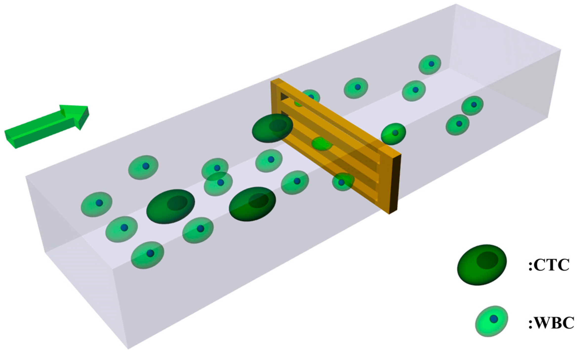
The Optimization of a Microfluidic CTC Filtering Chip by Simulation

 ,
,
Abstract
: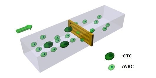
1. Introduction
2. Methods
3. Results and Discussion
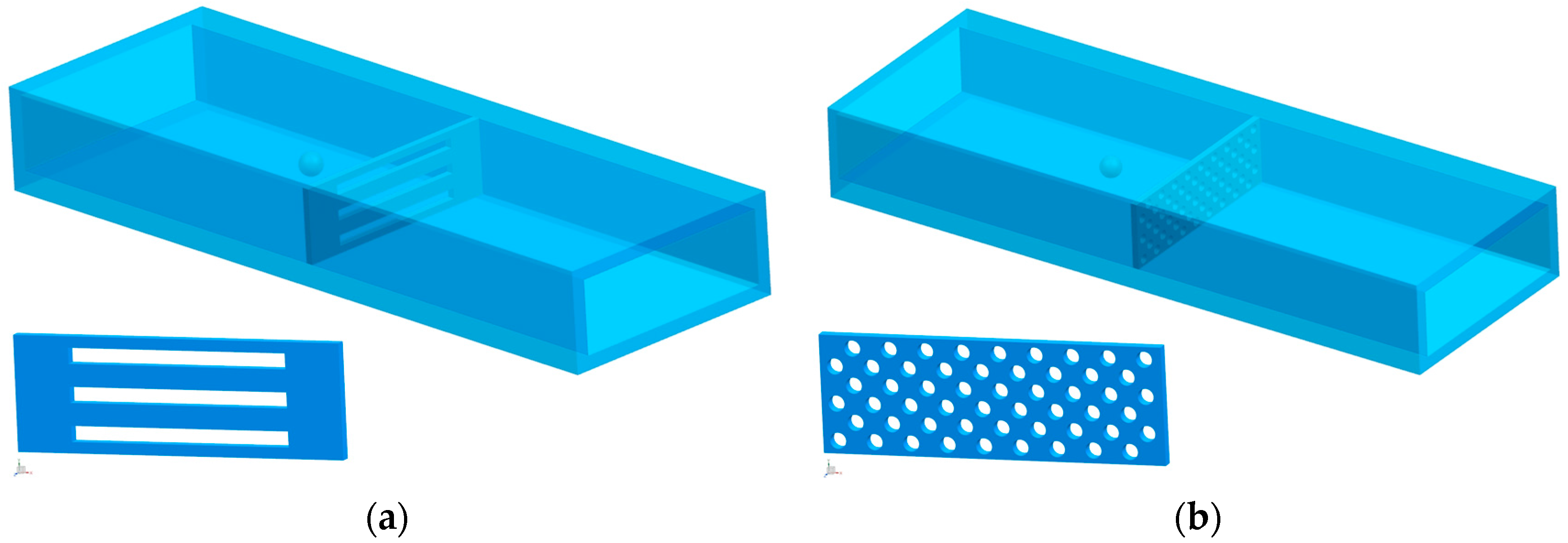
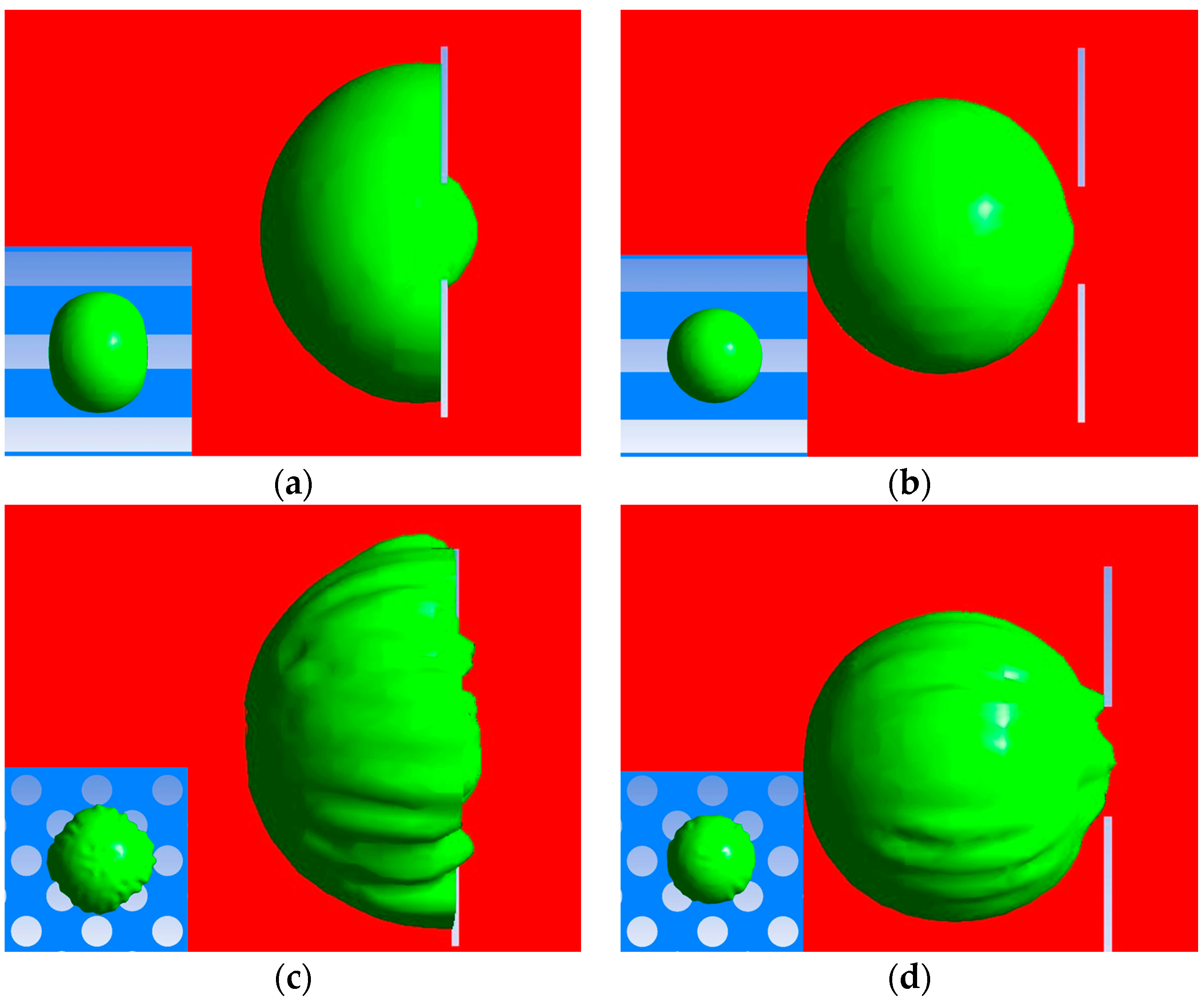
3.1. Geometry Comparison Analysis
3.1.1. Cellular Damage of the Passed WBCs
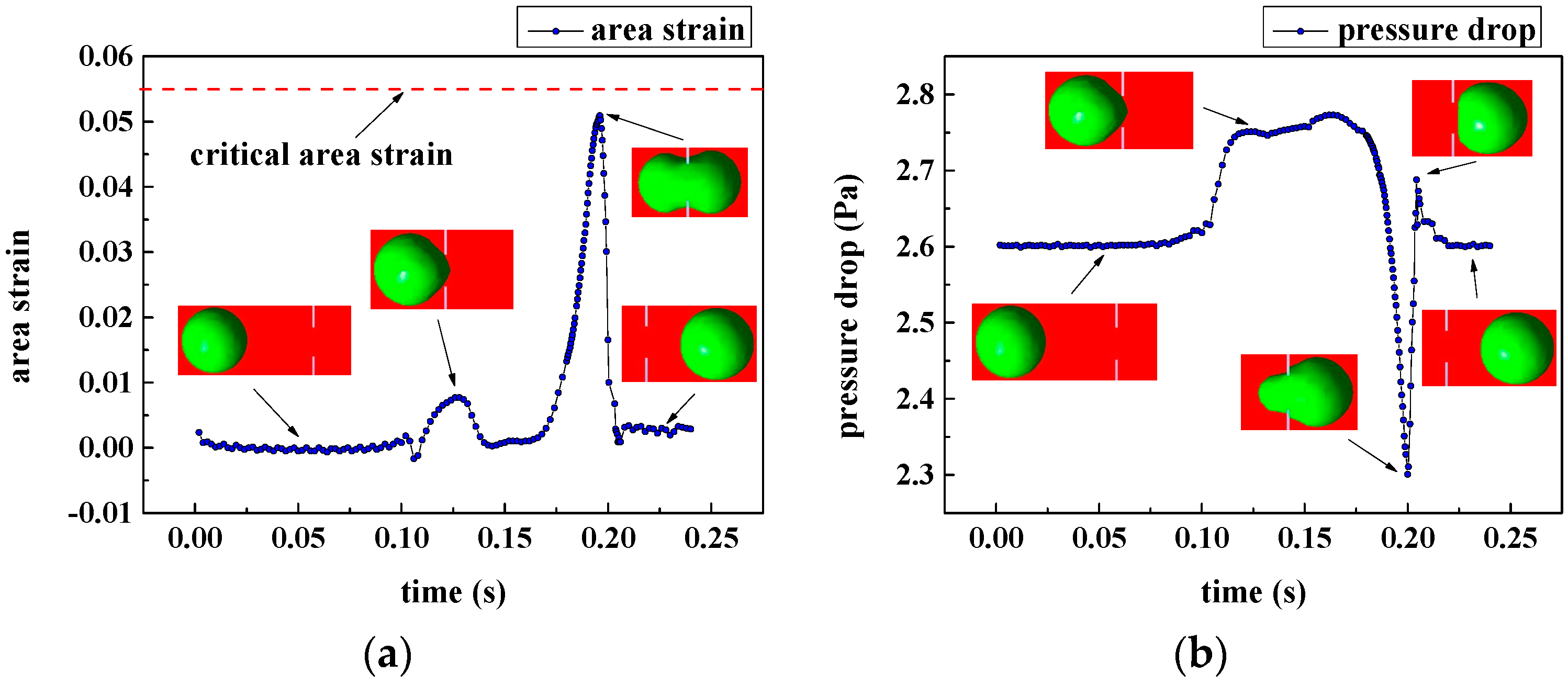
3.1.2. Cellular Damage of the Captured Circulating Tumor Cells (CTCs)
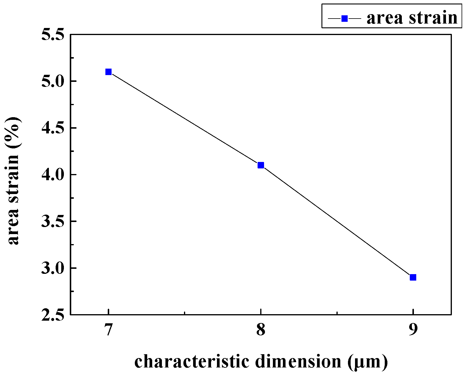
3.2. Characteristic Dimension Analysis
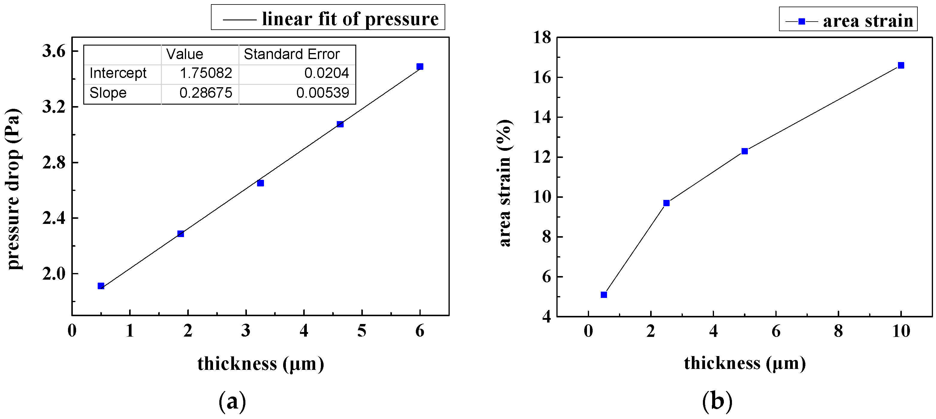
3.3. Film Thickness Analysis
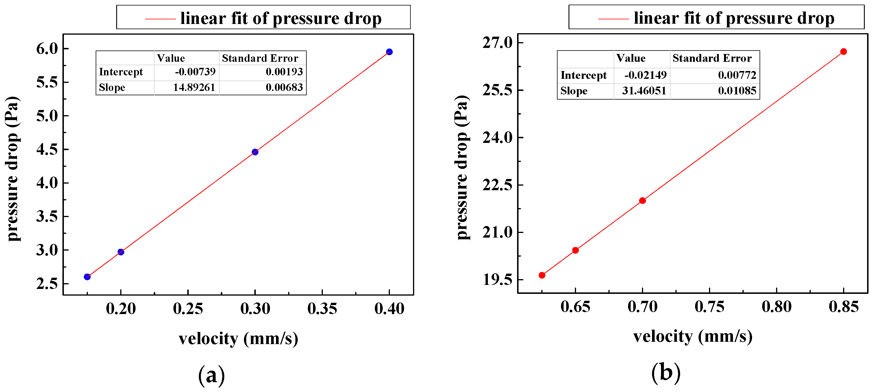
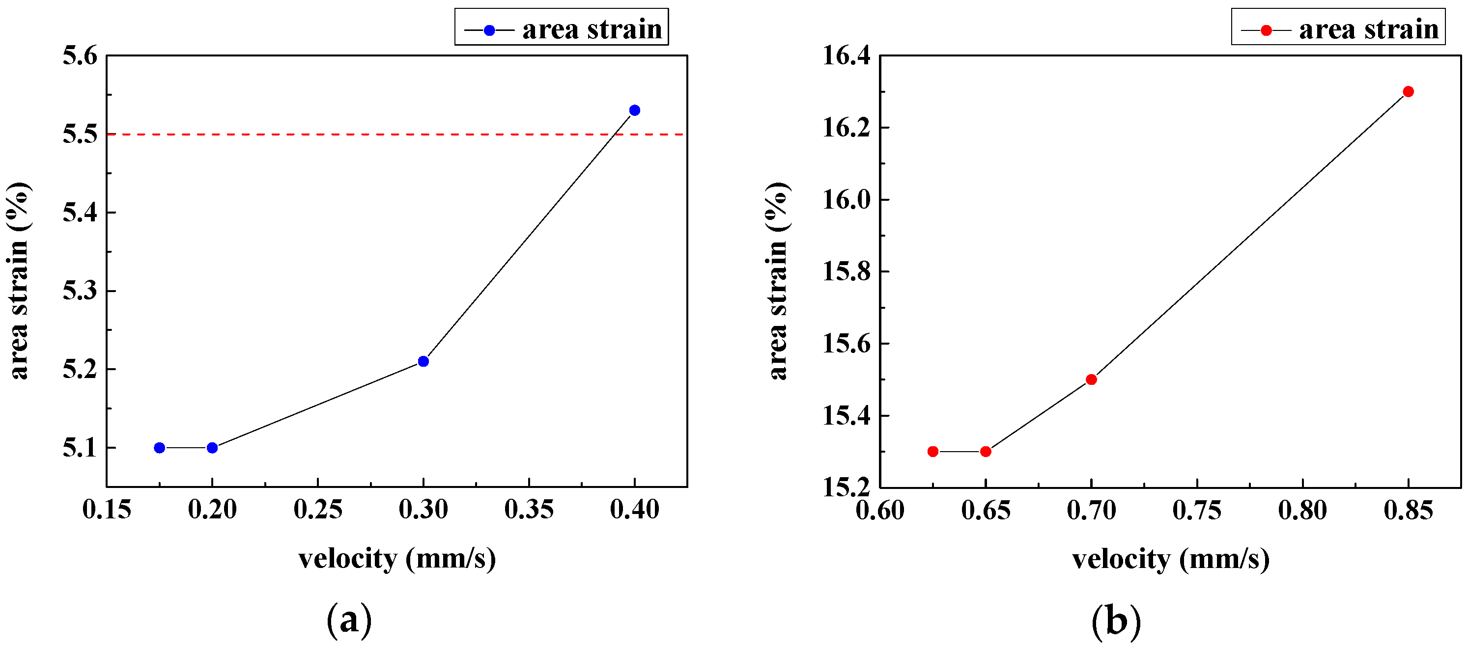
3.4. Velocity Optimization
4. Conclusions
Acknowledgments
Author Contributions
Conflicts of Interest
References
- Hong, B.; Zu, Y. Detecting circulating tumor cells: Current challenges and new trends. Theranostics 2013, 3, 377–394. [Google Scholar] [CrossRef] [PubMed]
- Plaks, V.; Koopman, C.D.; Werb, Z. Circulating tumor cells. Science 2013, 341, 1186–1188. [Google Scholar] [CrossRef] [PubMed]
- Williams, S.C. Circulating tumor cells. Proc. Natl. Acad. Sci. USA 2013, 110, 4861. [Google Scholar] [CrossRef] [PubMed]
- Cristofanilli, M.; Budd, G.T.; Ellis, M.J.; Stopeck, A.; Matera, J.; Miller, M.C.; Reuben, J.M.; Doyle, G.V.; Allard, W.J.; Terstappen, L.W. Circulating tumor cells, disease progression, and survival in metastatic breast cancer. N. Engl. J. Med. 2004, 351, 781–791. [Google Scholar] [CrossRef] [PubMed]
- Sarioglu, A.F.; Aceto, N.; Kojic, N.; Donaldson, M.C.; Zeinali, M.; Hamza, B.; Engstrom, A.; Zhu, H.; Sundaresan, T.K.; Miyamoto, D.T. A microfluidic device for label-free, physical capture of circulating tumor cell clusters. Nat. Methods 2015, 12, 685–691. [Google Scholar] [CrossRef] [PubMed]
- Thierry, B.; Kurkuri, M.; Shi, J.Y.; Lwin, L.E.M.P.; Palms, D. Herceptin functionalized microfluidic polydimethylsiloxane devices for the capture of human epidermal growth factor receptor 2 positive circulating breast cancer cells. Biomicrofluidics 2010, 4, 32205. [Google Scholar] [CrossRef] [PubMed]
- Patil, P.; Madhuprasad; Kumeria, T.; Losic, D.; Kurkuri, M. Isolation of circulating tumour cells by physical means in a microfluidic device: A review. RSC Adv. 2015, 5, 89745–89762. [Google Scholar] [CrossRef]
- Myung, J.H.; Hong, S. Microfluidic devices to enrich and isolate circulating tumor cells. Lab Chip 2015, 15, 4500. [Google Scholar] [CrossRef] [PubMed]
- Kurkuri, M.D.; Alejeh, F.; Shi, J.Y.; Palms, D.; Prestidge, C.; Griesser, H.J.; Brown, M.P.; Thierry, B. Plasma functionalized PDMS microfluidic chips: Towards point-of-care capture of circulating tumor cells. J. Mater. Chem. 2011, 21, 8841–8848. [Google Scholar] [CrossRef]
- Yoon, H.J.; Kim, T.H.; Zhang, Z.; Azizi, E.; Pham, T.M.; Paoletti, C.; Lin, J.; Ramnath, N.; Wicha, M.S.; Hayes, D.F. Sensitive capture of circulating tumour cells by functionalized graphene oxide nanosheets. Nat. Nanotechnol. 2013, 8, 735–741. [Google Scholar] [CrossRef] [PubMed]
- Lengauer, C.; Kinzler, K.W.; Vogelstein, B. Genetic instabilities in human cancers. Nature 1998, 396, 643–649. [Google Scholar] [CrossRef] [PubMed]
- McFaul, S.M.; Lin, B.K.; Ma, H. Cell separation based on size and deformability using microfluidic funnel ratchets. Lab Chip 2012, 12, 2369–2376. [Google Scholar] [CrossRef] [PubMed]
- Gossett, D.R.; Weaver, W.M.; Mach, A.J.; Hur, S.C.; Tse, H.T.K.; Lee, W.; Amini, H.; Di Carlo, D. Label-free cell separation and sorting in microfluidic systems. Anal. Bioanal. Chem. 2010, 397, 3249–3267. [Google Scholar] [CrossRef] [PubMed]
- Zhang, J.; Yan, S.; Yuan, D.; Alici, G.; Nguyen, N.-T.; Warkiani, M.E.; Li, W. Fundamentals and applications of inertial microfluidics: A review. Lab Chip 2016, 16, 10–34. [Google Scholar] [CrossRef] [PubMed]
- Yeo, T.; Tan, S.J.; Lim, C.L.; Lau, D.P.X.; Yong, W.C.; Krisna, S.S.; Iyer, G.; Tan, G.S.; Lim, T.K.H.; Tan, D.S.W. Microfluidic enrichment for the single cell analysis of circulating tumor cells. Sci. Rep. 2016, 6, 22076. [Google Scholar] [CrossRef] [PubMed]
- Warkiani, M.E.; Khoo, B.L.; Wu, L.; Tay, A.K.P.; Bhagat, A.A.S.; Han, J.; Lim, C.T. Ultra-fast, label-free isolation of circulating tumor cells from blood using spiral microfluidics. Nat. Protoc. 2016, 11, 134. [Google Scholar] [CrossRef] [PubMed]
- Sun, J.; Gao, Y.; Isaacs, R.J.; Boelte, K.C.; Lin, P.C.; Boczko, E.M.; Li, D. Simultaneous on-chip DC dielectrophoretic cell separation and quantitative separation performance characterization. Anal. Chem. 2012, 84, 2017–2024. [Google Scholar] [CrossRef] [PubMed]
- Kumeria, T.; Kurkuri, M.D.; Diener, K.R.; Parkinson, L.; Losic, D. Label-free reflectometric interference microchip biosensor based on nanoporous alumina for detection of circulating tumour cells. Biosens. Bioelectron. 2012, 35, 167. [Google Scholar] [CrossRef] [PubMed]
- Augustsson, P.; Karlsen, J.T.; Su, H.-W.; Bruus, H.; Voldman, J. Iso-acoustic focusing of cells for size-insensitive acousto-mechanical phenotyping. Nat. Commun. 2016, 7, 11556. [Google Scholar] [CrossRef] [PubMed]
- Hochmuth, R.M. Micropipette aspiration of living cells. J. Biomech. 2000, 33, 15–22. [Google Scholar] [CrossRef]
- Rosenbluth, M.J.; Lam, W.A.; Fletcher, D.A. Force microscopy of nonadherent cells: A comparison of leukemia cell deformability. Biophys. J. 2006, 90, 2994–3003. [Google Scholar] [CrossRef] [PubMed]
- Zheng, S.; Lin, H.K.; Lu, B.; Williams, A.; Datar, R.; Cote, R.J.; Tai, Y.-C. 3D microfilter device for viable circulating tumor cell (CTC) enrichment from blood. Biomed. Microdevices 2011, 13, 203–213. [Google Scholar] [CrossRef] [PubMed]
- Lee, A.; Park, J.; Lim, M.; Sunkara, V.; Kim, S.Y.; Kim, G.H.; Kim, M.-H.; Cho, Y.-K. All-in-one centrifugal microfluidic device for size-selective circulating tumor cell isolation with high purity. Anal. Chem. 2014, 86, 11349–11356. [Google Scholar] [CrossRef] [PubMed]
- Kojić, N.; Milošević, M.; Petrović, D.; Isailović, V.; Sarioglu, A.F.; Haber, D.A.; Kojić, M.; Toner, M. A computational study of circulating large tumor cells traversing microvessels. Comput. Biol. Med. 2015, 63, 187–195. [Google Scholar] [CrossRef] [PubMed]
- Leong, F.Y.; Li, Q.; Lim, C.T.; Chiam, K.-H. Modeling cell entry into a micro-channel. Biomech. Model. Mechanobiol. 2011, 10, 755–766. [Google Scholar] [CrossRef] [PubMed]
- Zhang, Z.; Xu, J.; Hong, B.; Chen, X. The effects of 3d channel geometry on CTC passing pressure-towards deformability-based cancer cell separation. Lab Chip 2014, 14, 2576–2584. [Google Scholar] [CrossRef] [PubMed]
- Zhang, Z.; Chen, X.; Xu, J. Entry effects of droplet in a micro confinement: Implications for deformation-based circulating tumor cell microfiltration. Biomicrofluidics 2015, 9, 024108. [Google Scholar] [CrossRef] [PubMed]
- Zhang, Z.; Xu, J.; Chen, X. Modeling cell deformation in CTC microfluidic filters. In Proceedings of the ASME 2014 International Mechanical Engineering Congress and Exposition, Montreal, QC, Canada, 14–20 November 2014; p. V003T003A034.
- Zhang, Z.; Xu, J.; Chen, X. Predictive model for the cell passing pressure in deformation-based CTC chips. In Proceedings of the ASME 2014 International Mechanical Engineering Congress and Exposition, Montreal, QC, Canada, 14–20 November 2014; p. V010T013A043.
- Zhang, Z.; Xu, J.; Chen, X. Compound droplet modelling of circulating tumor cell microfiltration. In Proceedings of the ASME 2015 International Mechanical Engineering Congress and Exposition, Houston, TX, USA, 13–19 November 2015; p. V07BT09A008.
- Fabbri, F.; Carloni, S.; Zoli, W.; Ulivi, P.; Gallerani, G.; Fici, P.; Chiadini, E.; Passardi, A.; Frassineti, G.L.; Ragazzini, A. Detection and recovery of circulating colon cancer cells using a dielectrophoresis-based device: Kras mutation status in pure CTCs. Cancer Lett. 2013, 335, 225–231. [Google Scholar] [CrossRef] [PubMed]
- Aghaamoo, M.; Zhang, Z.; Chen, X.; Xu, J. Deformability-based circulating tumor cell separation with conical-shaped microfilters: Concept, optimization, and design criteria. Biomicrofluidics 2016, 9, 85–94. [Google Scholar] [CrossRef] [PubMed]
- Yuan, F.; Yang, C.; Zhong, P. Cell membrane deformation and bioeffects produced by tandem bubble-induced jetting flow. Proc. Natl. Acad. Sci. USA 2015, 112, E7039–E7047. [Google Scholar] [CrossRef] [PubMed]
- Diz-Muñoz, A.; Fletcher, D.A.; Weiner, O.D. Use the force: Membrane tension as an organizer of cell shape and motility. Trends Cell Biol. 2013, 23, 47–53. [Google Scholar] [CrossRef] [PubMed]
- Stroetz, R.W.; Vlahakis, N.E.; Walters, B.J.; Schroeder, M.A.; Hubmayr, R.D. Validation of a new live cell strain system: Characterization of plasma membrane stress failure. J. Appl. Physiol. 2001, 90, 2361–2370. [Google Scholar] [PubMed]
- Shigematsu, T.; Koshiyama, K.; Wada, S. Effects of stretching speed on mechanical rupture of phospholipid/cholesterol bilayers: Molecular dynamics simulation. Sci. Rep. 2015, 5, 537–558. [Google Scholar] [CrossRef] [PubMed]
- Evans, E.A.; Waugh, R.; Melnik, L. Elastic area compressibility modulus of red cell membrane. Biophy. J. 1976, 16, 585. [Google Scholar] [CrossRef]
- Waugh, R.E. Forty-percent area strain in red cell membranes?—Doubtful. Biophys. J. 2014, 106, 1834–1835. [Google Scholar] [CrossRef] [PubMed]
- Glenn, E. Viscosity. 2011. Available online: http://physics.info/viscosity/ (accessed on 2 March 2017).
- Mastro, A.M.; Babich, M.A.; Taylor, W.D.; Keith, A.D. Diffusion of a small molecule in the cytoplasm of mammalian cells. Proc. Natl. Acad. Sci. USA 1984, 81, 3414–3418. [Google Scholar] [CrossRef] [PubMed]
- Bronzino, E.J.D. The Biomedical Engineering Handbook, 2nd ed.; CRC Press: Boca Raton, FL, USA, 2000. [Google Scholar]


| Parameters | Settings | Reference |
|---|---|---|
| CTC diameter | 10 μm | - |
| WBC diameter | 16 μm | - |
| Blood (main phase) viscosity | 0.0035 Pa·s | [39] |
| Cell (secondary phase) viscosity | 0.001 Pa·s | [40] |
| CTC surface tension | 0.03 N/m | [41] |
| WBC surface tension | 3 × 10⁻⁵ N/m | [20] |
| Pattern | 90° Contact Angle | 180° Contact Angle |
|---|---|---|
| Slit-shape | 10% | around 0 |
| Circle | 13% | 2.5% |
| Cell Type | Critical Velocity (mm/s) |
|---|---|
| CTC (10 μm) | 75 |
| WBC (16 μm) | 0.175 |
© 2017 by the authors. Licensee MDPI, Basel, Switzerland. This article is an open access article distributed under the terms and conditions of the Creative Commons Attribution (CC BY) license ( http://creativecommons.org/licenses/by/4.0/).
Share and Cite
Li, H.; Chen, J.; Du, W.; Xia, Y.; Wang, D.; Zhao, G.; Chu, J. The Optimization of a Microfluidic CTC Filtering Chip by Simulation. Micromachines 2017, 8, 79. https://doi.org/10.3390/mi8030079
Li H, Chen J, Du W, Xia Y, Wang D, Zhao G, Chu J. The Optimization of a Microfluidic CTC Filtering Chip by Simulation. Micromachines. 2017; 8(3):79. https://doi.org/10.3390/mi8030079
Chicago/Turabian StyleLi, Huan, Jianfeng Chen, Wenqiang Du, Youjun Xia, Depei Wang, Gang Zhao, and Jiaru Chu. 2017. "The Optimization of a Microfluidic CTC Filtering Chip by Simulation" Micromachines 8, no. 3: 79. https://doi.org/10.3390/mi8030079