Simulation, Fabrication and Analysis of Silver Based Ascending Sinusoidal Microchannel (ASMC) for Implant of Varicose Veins

 , , ,
, , ,  ,
,
Abstract
:1. Introduction
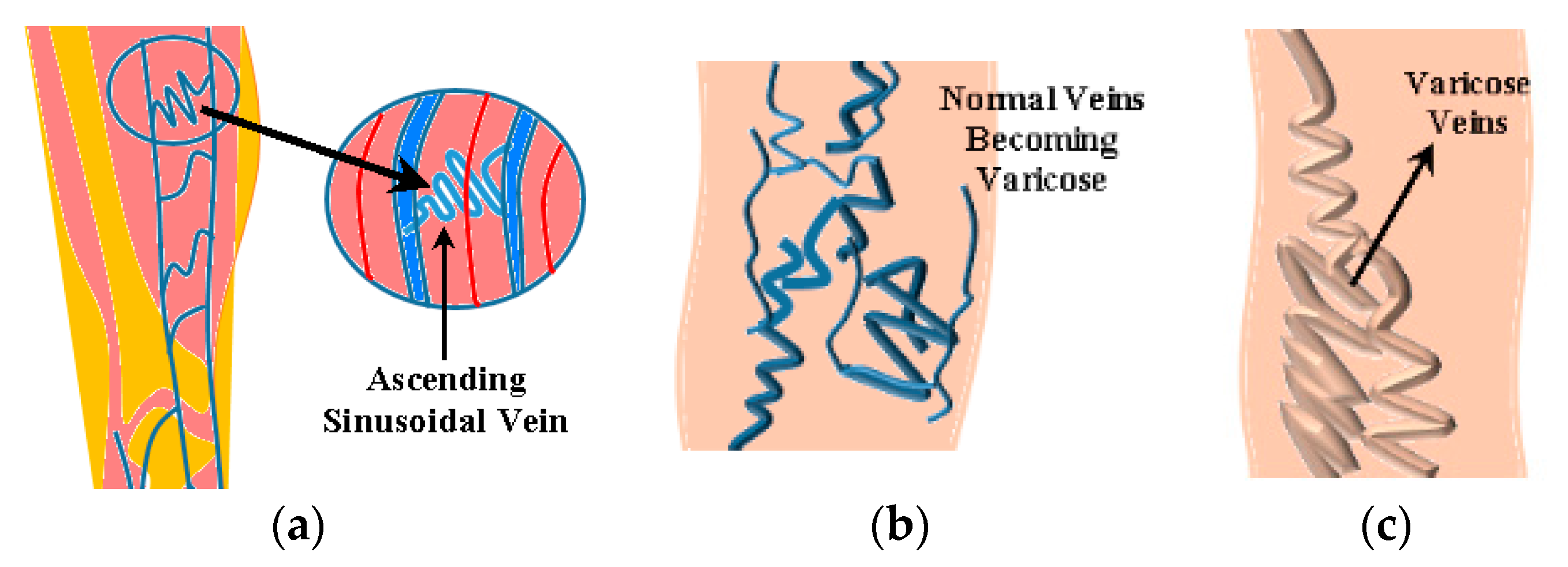
Complications of Varicose Veins after Ligation and Stripping
- Wound complications
- Leakage of lymph from the groin
- Deep vein thrombosis (DVT)
- Pulmonary embolus
- Vascular injury
- Damaged femoral vein
- Vein patch repair
2. Fuzzy Rule Based Parametric Estimation
3. ANSYS Simulation Based Parametric Estimation for ASMC
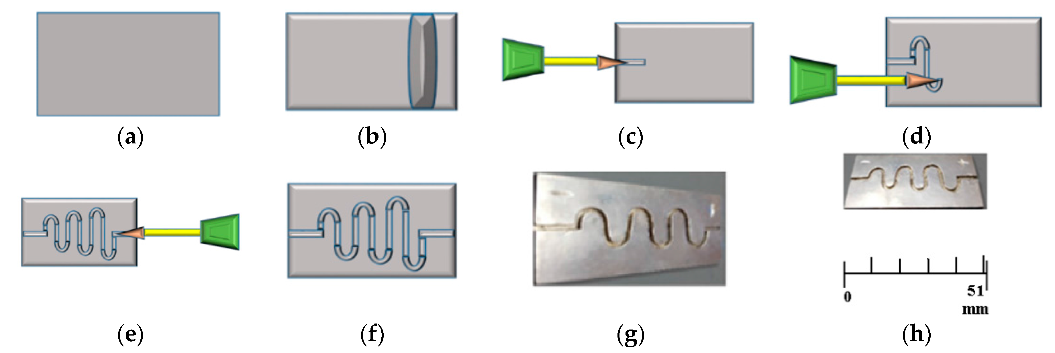
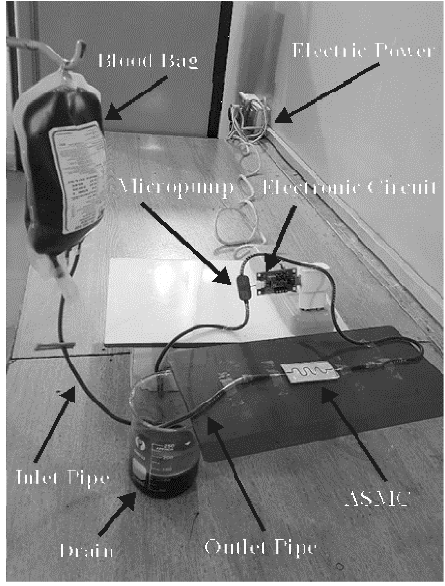
4. Fabrication, Testing, and Implant Procedure of ASMC
5. Results and Discussion
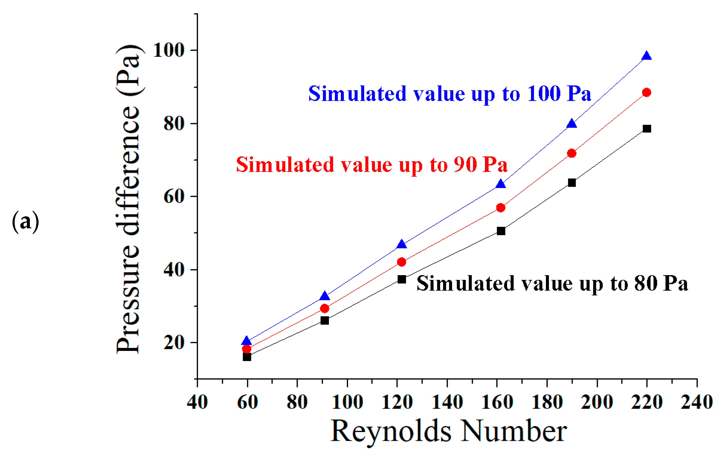
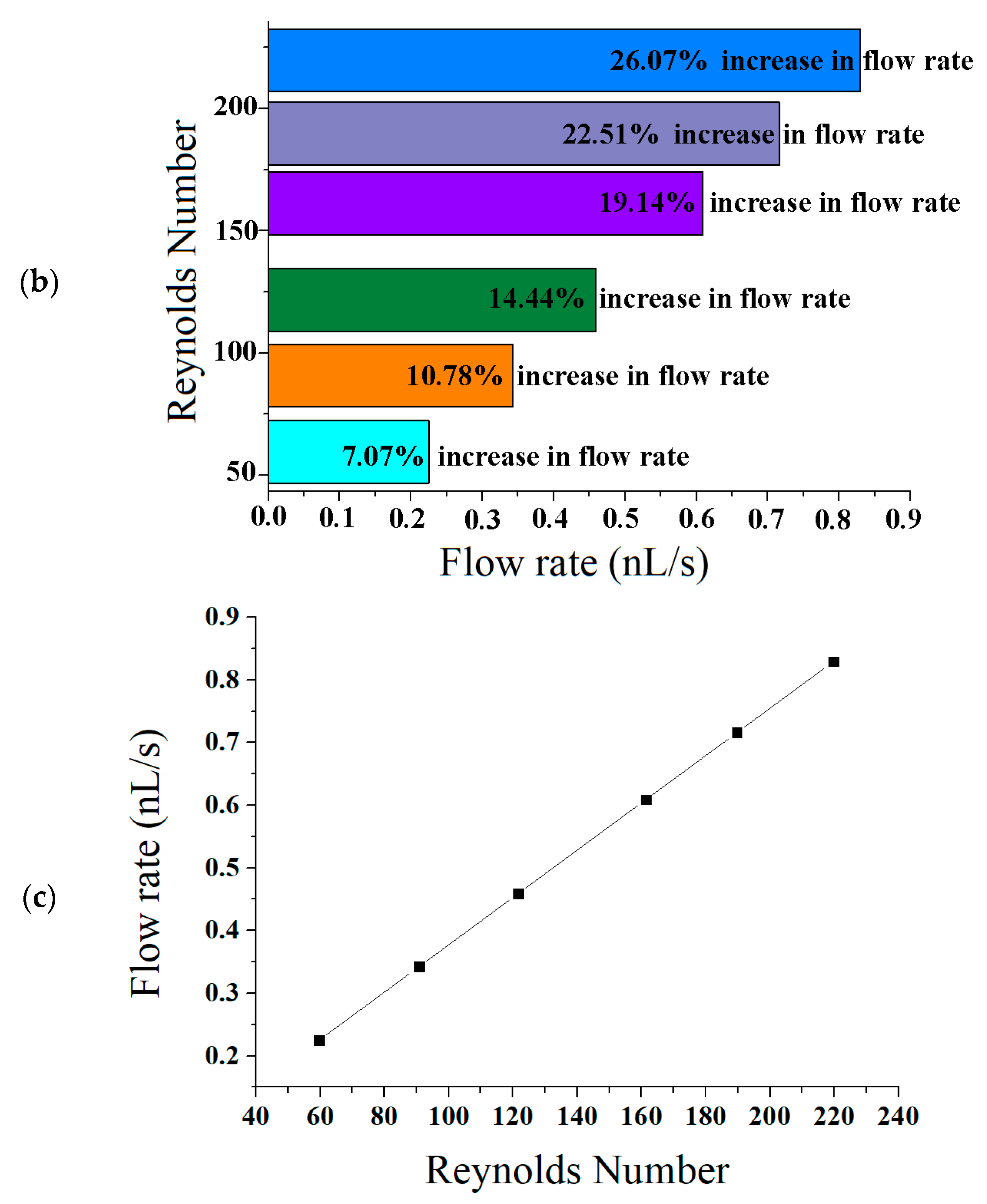
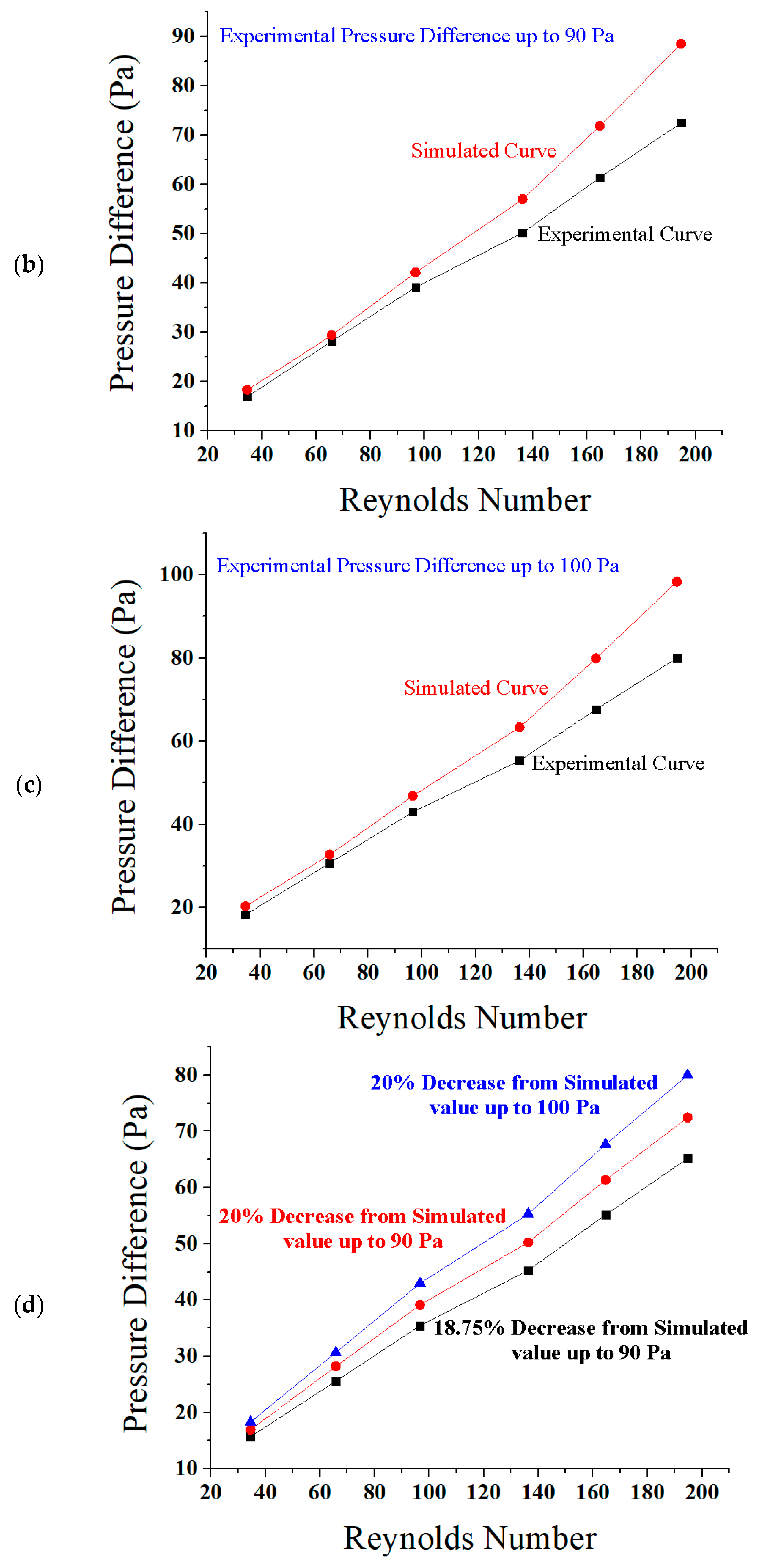
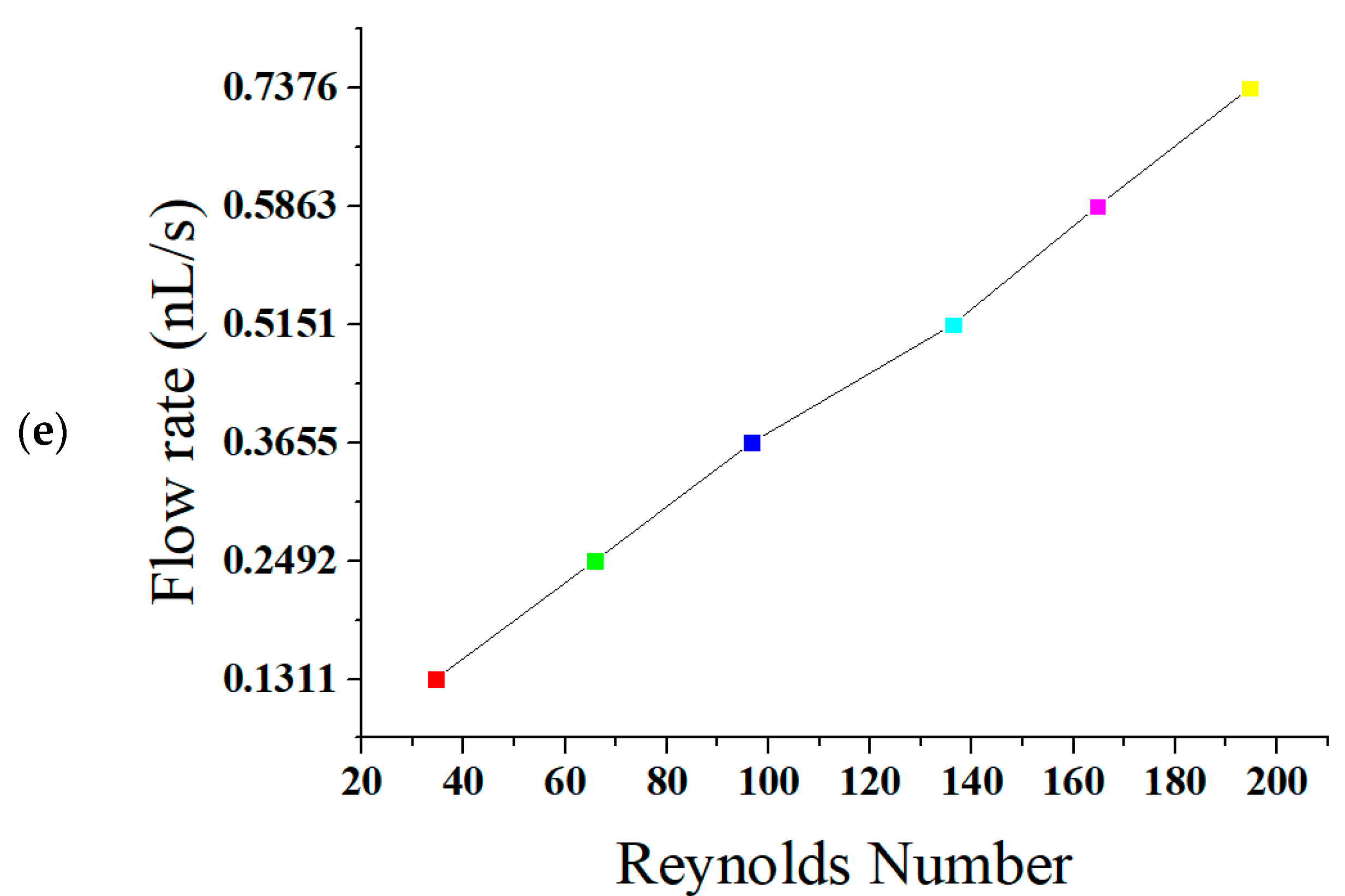
5.1. Reynolds Number, Pressure Difference, and Flow Rate
5.2. Implantation of Bioengineered Veins and Related Issues
5.3. Comparison of Results
6. Conclusions
Author Contributions
Conflicts of Interest
References
- Roy-Chaudhury, P. Dialysis: Bioengineered vessels for dialysis access: Soon to be a reality? Nat. Rev. Nephrol. 2016, 12, 516–517. [Google Scholar] [CrossRef] [PubMed]
- Rebello, K.J. Applications of MEMS in surgery. Proc. IEEE 2004, 92, 43–55. [Google Scholar] [CrossRef]
- Bhisitkul, R.; Keller, C. Development of Microelectromechanical Systems (MEMS) forceps for intraocular surgery. Br. J. Ophthalmol. 2005, 89, 1586–1588. [Google Scholar] [CrossRef] [PubMed]
- Folch, A. Introduction to bioMEMS; CRC Press: Boca Raton, FL, USA, 2016. [Google Scholar]
- Kandlikar, S.G. Microchannels and minichannels: History, terminology, classification and current research needs. In Proceedings of the ASME 2003 1st International Conference on Microchannels and Minichannels, Rochester, NY, USA, 24–25 April 2003. [Google Scholar]
- Weisberg, A.; Bau, H.H.; Zemel, J. Analysis of microchannels for integrated cooling. Int. J. Heat Mass Transf. 1992, 35, 2465–2474. [Google Scholar] [CrossRef]
- Abed, A.M.; Alghoul, M.A.; Sopian, K.; Mohammed, H.A.; Al-Shamani, A.N. Design characteristics of corrugated trapezoidal plate heat exchangers using nanofluids. Chem. Eng. Process. Process Intensif. 2015, 87, 88–103. [Google Scholar] [CrossRef]
- Shojaeian, M.; Koşar, A. Convective heat transfer of non-Newtonian power-law slip flows and plug flows with variable thermophysical properties in parallel-plate and circular microchannels. Int. J. Therm. Sci. 2016, 100, 155–168. [Google Scholar] [CrossRef]
- Lee, S.; Mudawar, I. Investigation of flow boiling in large micro-channel heat exchangers in a refrigeration loop for space applications. Int. J. Heat Mass Transf. 2016, 97, 110–129. [Google Scholar] [CrossRef]
- Afzal, A.; Kim, K.-Y. Flow and mixing analysis of non-Newtonian fluids in straight and serpentine microchannels. Chem. Eng. Sci. 2014, 116, 263–274. [Google Scholar] [CrossRef]
- Ashrafi, M.; Shams, M.; Bozorgnezhad, A.; Ahmadi, G. Simulation and experimental validation of droplet dynamics in microchannels of PEM fuel cells. Heat Mass Transf. 2016, 52, 2671–2686. [Google Scholar] [CrossRef]
- Cardiel, J.J.; Takagi, D.; Tsai, H.F.; Shen, A.Q. Formation and Flow Behavior of Micellar Membranes in a T-shaped Microchannel. Soft Matter 2016, 12, 8226–8234. [Google Scholar] [CrossRef] [PubMed]
- Tu, C.; Qian, L.; Bao, F.; Yan, W. Local effective viscosity of gas in nano-scale channels. Eur. J. Mech. B/Fluids 2017, 64, 55–59. [Google Scholar] [CrossRef]
- Zhang, Y. Poiseuille flow in a nano channel for different wall surface patterns. Int. J. Heat Mass Transf. 2016, 95, 243–248. [Google Scholar] [CrossRef]
- Law, M.; Lee, P.-S.; Balasubramanian, K. Experimental investigation of flow boiling heat transfer in novel oblique-finned microchannels. Int. J. Heat Mass Transf. 2014, 76, 419–431. [Google Scholar] [CrossRef]
- Law, M.; Lee, P.-S. Comparative Study of Temperature and Pressure Instabilities During Flow Boiling in Straight-and 10° Oblique-Finned Microchannels. Energy Procedia 2015, 75, 3105–3112. [Google Scholar] [CrossRef]
- Law, M.; Kanargi, O.B.; Lee, P.-S. Effects of varying oblique angles on flow boiling heat transfer and pressure characteristics in oblique-finned microchannels. Int. J. Heat Mass Transf. 2016, 100, 646–660. [Google Scholar] [CrossRef]
- Li, Y.; Wang, X.; Yuan, S.; Tan, S.K. Flow development in curved rectangular ducts with continuously varying curvature. Exp. Therm. Fluid Sci. 2016, 75, 1–15. [Google Scholar] [CrossRef]
- Andreussi, T.; Galletti, C.; Mauri, R.; Camarri, S.; Salvetti, M.V. Flow regimes in T-shaped micro-mixers. Comput. Chem. Eng. 2015, 76, 150–159. [Google Scholar] [CrossRef]
- Li, X.-B.; Oishi, M.; Oshima, M.; Li, F.C.; Li, S.J. Measuring elasticity-induced unstable flow structures in a curved microchannel using confocal micro particle image velocimetry. Exp. Therm Fluid Sci. 2016, 75, 118–128. [Google Scholar] [CrossRef]
- Liu, C.; Xue, C.; Hu, G. Sheathless Separation of Particles and Cells by Viscoelastic Effects in Straight Rectangular Microchannels. Procedia Eng. 2015, 126, 721–724. [Google Scholar] [CrossRef]
- Liu, C.; Xue, C.; Chen, X.; Shan, L.; Tian, Y.; Hu, G. Size-based separation of particles and cells utilizing viscoelastic effects in straight microchannels. Anal. Chem. 2015, 87, 6041–6048. [Google Scholar] [CrossRef] [PubMed]
- Rafeie, M.; Zhang, J.; Asadnia, M.; Li, W.; Warkiani, M.E. Multiplexing slanted spiral microchannels for ultra-fast blood plasma separation. Lab Chip 2016, 16, 2791–2802. [Google Scholar] [CrossRef] [PubMed]
- Abed, A.A.; Khalil, W.H. A Numerical Study of the Heat Transfer and Fluid Flow in Different Shapes of Microchannels. Al-Nahrain J. Eng. Sci. 2017, 19, 66–75. [Google Scholar]
- Jiang, C.; Ouyang, J.; Wang, L.; Liu, Q.; Wang, X. Transport properties and structure of dense methane fluid in the rough nano-channels using non-equilibrium multiscale molecular dynamics simulation. Int. J. Heat Mass Transf. 2017, 110, 80–93. [Google Scholar] [CrossRef]
- Zhang, Y. Effect of wall surface roughness on mass transfer in a nano channel. Int. J. Heat Mass Transf. 2016, 100, 295–302. [Google Scholar] [CrossRef]
- Nayak, A.; Haque, A.; Banerjee, A.; Weigand, B. Flow mixing and electric potential effect of binary fluids in micro/nano channels. Coll. Surf. A Physicochem. Eng. Asp. 2017, 512, 145–157. [Google Scholar] [CrossRef]
- Politi, Y.; Pippel, E.; Licuco-Massouh, A.C.; Bertinetti, L.; Blumtritt, H.; Barth, F.G.; Fratzl, P. Nano-channels in the spider fang for the transport of Zn ions to cross-link His-rich proteins pre-deposited in the cuticle matrix. Arthropod Struct. Dev. 2017, 46, 30–38. [Google Scholar] [CrossRef] [PubMed]
- Campbell, T.; Bhattacharya, A.; Reisner, W. DNA dynamics squeezed inside a nano-channel with a sliding gasket. In Proceedings of the APS March Meeting 2017, New Orleans, LA, USA, 13–17 March 2017. [Google Scholar]
- Fried, J.R. Ion Transport Through Biomimetic Nanochannel Membranes. In Membranes; Springer: Berlin, Germany, 2017; pp. 61–66. [Google Scholar]
- Al-Neama, A.F.; Kapur, N.; Summers, J.; Thompson, H.M. An experimental and numerical investigation of the use of liquid flow in serpentine microchannels for microelectronics cooling. Appl. Therm. Eng. 2017, 116, 709–723. [Google Scholar] [CrossRef]
- Li, Q.; Delorme, Y.; Frankel, S.H. Parametric numerical study of electrokinetic instability in cross-shaped microchannels. Microfluid. Nanofluid. 2016, 20, 1–12. [Google Scholar] [CrossRef]
- Liu, C.; Hu, G.; Jiang, X.; Sun, J. Inertial focusing of spherical particles in rectangular microchannels over a wide range of Reynolds numbers. Lab Chip 2015, 15, 1168–1177. [Google Scholar] [CrossRef] [PubMed]
- Nivedita, N.; Ligrani, P.; Papautsky, I. Evolution of secondary dean vortices in spiral microchannels for cell separations. In Proceedings of the 17th International Conference on Miniaturized Systems for Chemistry and Life Sciences, Freiburg, Germany, 27–31 October 2013. [Google Scholar]
- Ma, S.; Sherwood, J.M.; Huck, W.T.; Balabani, S. On the flow topology inside droplets moving in rectangular microchannels. Lab Chip 2014, 14, 3611–3620. [Google Scholar] [CrossRef] [PubMed]
- Xue, C.; Chen, X.; Liu, C.; Hu, G. Lateral migration of dual droplet trains in a double spiral microchannel. Sci. China Phys. Mech. Astron. 2016, 59, 1–10. [Google Scholar] [CrossRef]
- Zhang, S.; Tang, Y.; Yuan, W.; Zeng, J.; Xie, Y. A comparative study of flow boiling performance in the interconnected microchannel net and rectangular microchannels. Int. J. Heat Mass Transf. 2016, 98, 814–823. [Google Scholar] [CrossRef]
- Yoon, D.H.; Ha, J.B.; Bahk, Y.K.; Arakawa, T.; Shoji, S.; Go, J.S. Size-selective separation of micro beads by utilizing secondary flow in a curved rectangular microchannel. Lab Chip 2009, 9, 87–90. [Google Scholar] [CrossRef] [PubMed]
- Jackson, J.M.; Witek, M.A.; Soper, S.A. Sinusoidal microchannels with high aspect ratios for CTC selection and analysis. Circ. Tumor Cells Isol. Anal. 2015, 85–126. [Google Scholar] [CrossRef]
- Chiam, Z.L.; Lee, P.S.; Singh, P.K.; Mou, N. Investigation of fluid flow and heat transfer in wavy micro-channels with alternating secondary branches. Int. J. Heat Mass Transf. 2016, 101, 1316–1330. [Google Scholar] [CrossRef]
- Solehati, N.; Bae, J.; Sasmito, A.P. Numerical investigation of mixing performance in microchannel T-junction with wavy structure. Comput. Fluids 2014, 96, 10–19. [Google Scholar] [CrossRef]
- Khoshvaght-Aliabadi, M.; Sahamiyan, M.; Hesampour, M.; Sartipzadeh, O. Experimental study on cooling performance of sinusoidal-wavy minichannel heat sink. Appl.Therm. Eng. 2016, 92, 50–61. [Google Scholar] [CrossRef]
- Heshmatnezhad, F.; Aghaei, H.; Nazar, S.; Reza, A. Parametric Study of Obstacle Geometry Effect on Mixing Performance in a Convergent-Divergent Micromixer with Sinusoidal Walls. Chem. Prod. Process Model. 2017, 12. [Google Scholar] [CrossRef]
- Li, H.; Chen, J.; Du, W.; Xia, Y.; Wang, D.; Zhao, G.; Chu, J. The Optimization of a Microfluidic CTC Filtering Chip by Simulation. Micromachines 2017, 8, 79. [Google Scholar] [CrossRef]
- Ashraf, M.W.; Tayyaba, S.; Afzulpurkar, N. Micro electromechanical systems (MEMS) based microfluidic devices for biomedical applications. Int. J Mol. Sci. 2011, 12, 3648–3704. [Google Scholar] [CrossRef] [PubMed]
- Shourav, M.K.; Kim, K.; Kim, S.; Kim, J.K. Wide Field-of-View Fluorescence Imaging with Optical-Quality Curved Microfluidic Chamber for Absolute Cell Counting. Micromachines 2016, 7, 125. [Google Scholar] [CrossRef]
- Kim, C.M.; Kim, G.M. 1600 Parallel Microchamber Microfluidic Device for Fast Sample Array Preparation Using the Immiscibility of Two Liquids. Micromachines 2017, 8, 63. [Google Scholar] [CrossRef]
- Testa, G.; Persichetti, G. Bernini, R. Liquid core ARROW waveguides: A promising photonic structure for integrated optofluidic microsensors. Micromachines 2016, 7, 47. [Google Scholar] [CrossRef]
- Martínez-López, J.I.; Betancourt, H.A.; García-López, E.; Rodriguez, C.A.; Siller, H.R. Rapid Fabrication of Disposable Micromixing Arrays Using Xurography and Laser Ablation. Micromachines 2017, 8, 144. [Google Scholar] [CrossRef]
- Rudyak, V.; Minakov, A. Modeling and optimization of Y-type micromixers. Micromachines 2014, 5, 886–912. [Google Scholar] [CrossRef]
- Tayyaba, S.; Ashraf, M.W.; Afzulpurkar, N. Design, Simulation, and Fabrication of Microneedles and a Blood Filter for Use in a Hemofiltration System. IEEE Trans. Autom. Sci. Eng. 2013, 10, 252–266. [Google Scholar] [CrossRef]
- Bootun, R.; Epstein, D.; Onida, S.; Ortega-Ortega, M.; Davies, A. Effectiveness of Treatments of Varicose Veins in Terms of Reintervention: Systematic Review and Evidence Synthesis. J. Vasc. Surg. Venous Lymphat. Disord. 2017, 5, 152. [Google Scholar] [CrossRef]
- Lawaetz, M.; Serup, J.; Lawaetz, B.; Bjoern, L.; Blemings, A.; Eklof, B.; Rasmussen, L. Comparison of endovenous radiofrequency ablation, laser ablation, foam sclerotherapy and surgical stripping for great saphenous varicose veins. Extended 5-year follow-up of a RCT. Int. Angiol. J. Int. Union Angiol. 2017, 53, e14. [Google Scholar] [CrossRef]
- Critchley, G.; Handa, A.; Maw, A.; Harvey, A.; Harvey, M.R.; Corbett, C.R. Complications of varicose vein surgery. Ann. R. Coll. Surg. Engl. 1997, 79, 105. [Google Scholar] [PubMed]
- Watters, D.A.; Hollands, M.J.; Gruen, R.L.; Maoate, K.; Perndt, H.; McDougall, R.J.; Morriss, W.W.; Tangi, V.; Casey, K.M.; McQueen, K.A. Perioperative mortality rate (POMR): A global indicator of access to safe surgery and anaesthesia. World J. Surg. 2015, 39, 856–864. [Google Scholar] [CrossRef] [PubMed]
- Gloviczki, P.; Lawrence, P.F. Iliac vein stenting and contralateral deep vein thrombosis. J. Vasc. Surg. Venous Lymphat. Disord. 2017, 5, 5–6. [Google Scholar] [CrossRef] [PubMed]
- Glueck, C.J.; Lee, K.; Prince, M.; Jetty, V.; Shah, P.; Wang, P. Four Thrombotic Events Over 5 Years, Two Pulmonary Emboli and Two Deep Venous Thrombosis, When Testosterone-HCG Therapy Was Continued Despite Concurrent Anticoagulation in a 55-Year-Old Man With Lupus Anticoagulant. J. Investig. Med. High Impact Case Rep. 2016, 4, 2324709616661833. [Google Scholar] [CrossRef] [PubMed]
- Versteeg, M.P.; Macfarlane, J.; Hill, G.B.; van Rij, A.M. The natural history of ultrasound-detected recurrence in the groin following saphenofemoral treatment for varicose veins. J. Vasc. Surg. Venous Lymphat. Disord. 2016, 4, 293–300. [Google Scholar] [CrossRef] [PubMed]
- Sakata, T.; Mogi, K.; Sakurai, M.; Nomura, A.; Fujii, M.; Takahara, Y. Popliteal Artery Pseudoaneurysm Caused By Osteochondroma. Ann. Vasc. Surg. 2017, 18, 121–123. [Google Scholar] [CrossRef] [PubMed]
- Lawaetz, J.; Lawaetz, M.; Rasmussen, L. Percutaneous Ligation of the Saphenous Veins With Ultrasound Guided Foam Sclerotherapy And Miniphlebectomies. Eur. J. Vasc. Endovasc. Surg. 2017, 53, e14–e15. [Google Scholar] [CrossRef]
- Pires, M.F.B.; Nogueira, R.F.; Navarro, T.P. Chronic Venous Disease and Varicose Veins. In Vascular Diseases for the Non-Specialist; Springer: Berlin, Germany, 2017; pp. 167–181. [Google Scholar]
- Audebert, C.; Bucur, P.; Bekheit, M.; Vibert, E.; Vignon-Clementel, I.E.; Gerbeau, J.F. Kinetic scheme for arterial and venous blood flow, and application to partial hepatectomy modeling. Comput. Methods Appl. Mech. Eng. 2017, 314, 102–125. [Google Scholar] [CrossRef]
- Masuda, H.; Ito, K.; Oshima, T.; Sasaki, K. Comparison between numerical simulation and visualization experiment on water behavior in single straight flow channel polymer electrolyte fuel cells. J. Power Sour. 2008, 177, 303–313. [Google Scholar] [CrossRef]
- Nishimura, T.; Kojima, N. Mass transfer enhancement in a symmetric sinusoidal wavy-walled channel for pulsatile flow. Int. J. Heat Mass Transf. 1995, 38, 1719–1731. [Google Scholar] [CrossRef]
- Lu, Z.; Rath, C.; Zhang, G.; Kandlikar, S.G. Water management studies in PEM fuel cells, part IV: Effects of channel surface wettability, geometry and orientation on the two-phase flow in parallel gas channels. Int. J. Hydrogen Energy 2011, 36, 9864–9875. [Google Scholar] [CrossRef]
- Khan, M.S.; Benkrid, K. Multi-Dimensional Supervisory Fuzzy Logic Time Control DEV Processing System for Industrial Applications. In Proceedings of the International MultiConference of Engineers and Computer Scientists, Hong Kong, China, 18–20 March 2009. [Google Scholar]
- Beech, K.E.; Biddlecombe, J.G.; van der Walle, C.F.; Stevens, L.A.; Rigby, S.P.; Burley, J.C.; Allen, S. Insights into the influence of the cooling profile on the reconstitution times of amorphous lyophilized protein formulations. Eur. J. Pharm. Biopharm. 2015, 96, 247–254. [Google Scholar] [CrossRef] [PubMed]
- Tayyaba, S.; Afzal, M.J.; Sarwar, G.; Ashraf, M.W.; Afzulpurkar, N. Simulation of flow control in straight microchannels using fuzzy logic. In Proceedings of the 2016 International Conference on Computing, Electronic and Electrical Engineering (ICE Cube), Quetta, Pakistan, 11–12 April 2016. [Google Scholar]
- Sivanandam, S.; Sumathi, S.; Deepa, S. Introduction to Fuzzy Logic Using MATLAB; Springer: Berlin, Germany, 2007; Volume 1. [Google Scholar]
- Martinez, R.; Fierro, C.A.; Shireman, P.K.; Han, H.C. Mechanical buckling of veins under internal pressure. Ann. Biomed. Eng. 2010, 38, 1345–1353. [Google Scholar] [CrossRef] [PubMed]
- Zhang, J.; Zhang, P.; Fraser, K.H.; Griffith, B.P.; Wu, Z.J. Comparison of fluid dynamic numerical models for a clinical ventricular assist device and experimental validation. Artif. Organs 2013, 37, 380. [Google Scholar] [CrossRef] [PubMed]
- Shih, T.-C.; Hsiao, H.-D.; Chen, P.-Y.; Tu, C.-Y.; Tseng, T.-I.; Ho, Y.-J. Study of pre-and post-stent implantation in the trachea using computational fluid dynamics. J. Med. Biol. Eng. 2014, 34, 150–156. [Google Scholar] [CrossRef]
- Qian, Y.; Liu, J.L.; Itatani, K.; Miyaji, K.; Umezu, M. Computational hemodynamic analysis in congenital heart disease: Simulation of the Norwood procedure. Ann. Biomed. Eng. 2010, 38, 2302–2313. [Google Scholar] [CrossRef] [PubMed]
- Heck, M.L.; Yen, A.; Snyder, T.A.; O'Rear, E.A.; Papavassiliou, D.V. Flow-Field Simulations and Hemolysis Estimates for the Food and Drug Administration Critical Path Initiative Centrifugal Blood Pump. Artif. Organs 2017, 18, 121–123. [Google Scholar] [CrossRef] [PubMed]
- Rahman, I.A. Computational fluid dynamics as a tool for testing functional and ecological hypotheses in fossil taxa. Palaeontology 2017, 4, 451–459. [Google Scholar] [CrossRef]
- Cherng, W.-J.; Dong, Z.-S.; Chou, C.-C.; Yeh, C.-H.; Pan, Y.-H. Hydrodynamic Simulation of an Orbital Shaking Test for the Degradation Assessment of Blood-Contact Biomedical Coatings. Micromachines 2017, 8, 132. [Google Scholar] [CrossRef]
- Elblbesy, M.A.; Hereba, A.T. Computation of the Coefficients of the Power law model for Whole Blood and Their Correlation with Blood Parameters. Appl. Phys. Res. 2016, 8, 1. [Google Scholar] [CrossRef]
- Choi, S.Y.; Kwak, B.K.; Seo, T. Mathematical modeling of radiofrequency ablation for varicose veins. Comput. Math. Methods Med. 2014, 2014. [Google Scholar] [CrossRef] [PubMed]
- Barnard, T.E. Computer Applications in Hydraulic Engineering; Haestad Press: Mishawaka, IN, USA, 2002. [Google Scholar]
- Gupta, R.; Fletcher, D.F.; Haynes, B.S. On the CFD modelling of Taylor flow in microchannels. Chem. Eng. Sci. 2009, 64, 2941–2950. [Google Scholar] [CrossRef]
- Cabezón, D.; Migoya, E.; Crespo, A. Comparison of turbulence models for the computational fluid dynamics simulation of wind turbine wakes in the atmospheric boundary layer. Wind Energy 2011, 14, 909–921. [Google Scholar] [CrossRef] [Green Version]
- Dolgin, E. Taking tissue engineering to heart: More than a decade after Japanese scientists implanted the first bioengineered blood vessel into a child with a congenital heart defect, the experimental treatment has finally made its way into clinical testing in the US. Elie Dolgin asks what took so long and what lessons have been learned along the way. Nat. Med. 2011, 17, 1032–1036. [Google Scholar] [PubMed]
- Kübler, P.; Reczuch, K. Optimal Stent Treatment of Cardiogenic Shock Complicating Acute Myocardial Infarction: Bare-Metal or Drug-Eluting Stent? BMJ Publishing Group Ltd.; British Cardiovascular Society: London, UK, 2017. [Google Scholar]
- Hennessey, D.B.; Kinnear, N.J.; Evans, R.M.; Hagan, C.; Thwaini, A. Is confirmation of ureteric stent placement in laparoscopic pyeloplasty necessary? Int. Urol. Nephrol. 2017, 49, 1–6. [Google Scholar] [CrossRef] [PubMed]
- Thakur, D.K.; Chapagain, S.; Luitel, B.R.; Chalise, P.R.; Sharma, U.K.; Gyawali, P.R. Efficacy of Tamsulosin in relieving double-J stent-related symptoms: A randomized controlled study. J. Soc. Surg. Nepal 2016, 18, 38. [Google Scholar] [CrossRef]
- Hansen, D.C. Metal corrosion in the human body: The ultimate bio-corrosion scenario. Electrochem. Soc. Interface 2008, 17, 31. [Google Scholar]
- Ragheb, A.O.; Bates, B.L.; Fearnot, N.E.; Osborne, T.A.; Kozma, T.G.; Roberts, J.W.; Voorhees III, W.D. Silver Implantable Medical Device. U.S. Patent 5,873,904, 23 Feburary 1999. [Google Scholar]
- Oloffs, A.; Grosse-Siestrup, C.; Bisson, S.; Rinck, M.; Rudolph, R.; Gross, U. Biocompatibility of silver-coated polyurethane catheters and silvercoated Dacron® material. Biomaterials 1994, 15, 753–758. [Google Scholar] [CrossRef]
- Mihov, D.; Katerska, B. Some biocompatible materials used in medical practice. Trakia J. Sci. 2010, 8, 119–125. [Google Scholar]
- Groisman, A.; Enzelberger, M.; Quake, S.R. Microfluidic memory and control devices. Science 2003, 300, 955–958. [Google Scholar] [CrossRef] [PubMed]
- Guan, G.; Wu, L.; Bhagat, A.A.; Li, Z.; Chen, P.C.; Chao, S.; Ong, C.J.; Han, J. Spiral microchannel with rectangular and trapezoidal cross-sections for size based particle separation. Sci. Rep. 2013, 3, 1475. [Google Scholar] [CrossRef] [PubMed]


| References | Length | Channel Type | Fabrication Technique | Fluid | Flow Rate | Simulation/Experiment | Applications |
|---|---|---|---|---|---|---|---|
| Abed et al. [7] | 95 mm | Trapezoidal | Not reported | Water | Not reported | ANSYS Fluent 6.3 | Heat exchangers |
| Shojaeian and Kosar [8] | 1000 µm | Circular | Not reported | Water | Not reported | ANSYS Fluent 14.0 | Heat transfer characteristics |
| Zhang et al. [37] | 45 × 20 × 2 mm3 | Straight rectangular | WEDM | Water | 4.8 mL/min | Experiment | Heat transfer characteristics |
| Afzal and Kim [10] | 2.8 mm | Straight and serpentine | Not reported | Blood | Not reported | ANSYS CFD | Flow dynamics and mixing behavior |
| Ashrafi et al. [11] | 4 mm | Straight and serpentine | Not reported | Water | Not reported | Numerical | PEM fuel cells |
| Cardiel et al. [12] | 2 cm | T-shaped | Standard soft lithography | Water | 4000 μL/h | Not Reported | Instability behavior of membranes |
| Masuda et al. [63] | 30 × 3.2 mm2 | Straight | Simple machining process | Water | 58,116 and 232 cm3/min | PEFC | Mass transportation PEM/GDL and GDL/GFC |
| Nishimura and Matsune [64] | 14 mm | Sinusoidal | Simple machining process | Water | 2.5 m3/s | Experiment | Heat transfer characteristics |
| Lu et al. [65] | 183 mm | Sinusoidal | Simple machining process | Water/air | 0.02–0.2 mL/min | Experiment | PEM fuel cell |
| Membership Functions | Reynolds Number | Pressure (kPa) | Curve Height (mm) | % Loss | Flow Rate (0.1 nL/s) | Velocity (cm/s) | ||||||
|---|---|---|---|---|---|---|---|---|---|---|---|---|
| Ranges | MFs | Ranges | MFs | Ranges | MFs | Ranges | MFs | Ranges | MFS | Ranges | MFs | |
| MF1 | 0–500 | SMALLEST | 1–1.25 | LOW | 5–6 | SMALL | 0.1–0.55 | SMALL | 0–5 | SMALL | 2–4.5 | SMALL |
| MF2 | 0–1000 | SMALLER | 1–1.5 | MEDIUM | 5–7 | MEDIUM | 0.1–1 | MEDIUM | 0–10 | MEDIUM | 2–7 | MEDIUM |
| MF3 | 500–1000 | SMAL | 1.25–1.5 | HIGH | 6–7 | HIGH | 0.55–1 | LARGE | 5–10 | HIGH | 4.5–7 | HIGH |
| Category | Flow Rate (0.1 nL/s) | Velocity (cm/s) |
|---|---|---|
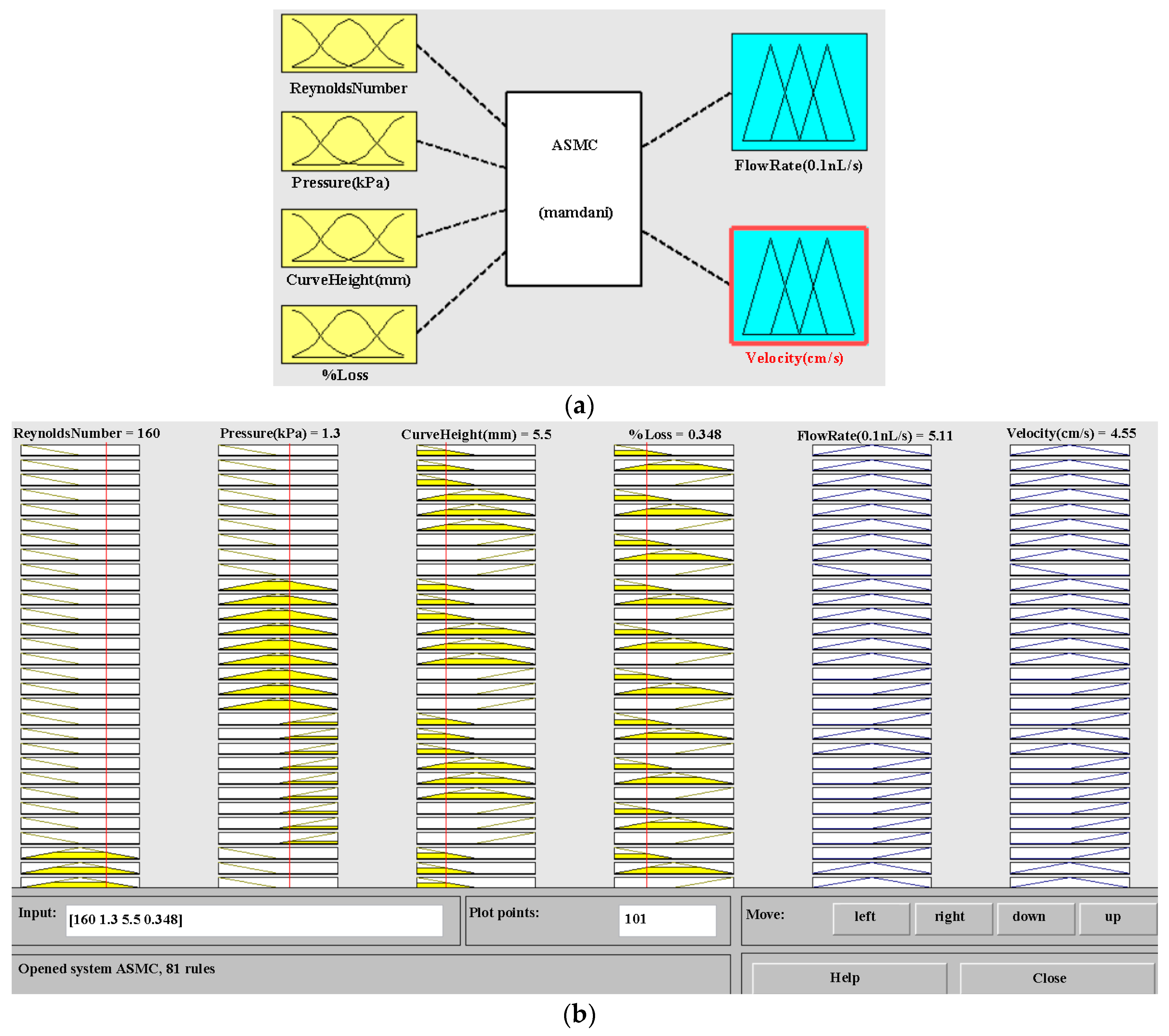
| Mamdani’s value | 5.15 | 4.65 |
| MATLAB simulation | 5.11 | 4.55 |
| Difference | 0.04 | 0.1 |
| Error percentage | 0.78% | 2.19% |
| MATLAB Results | ANSYS Results | Experimental Results |
|---|---|---|
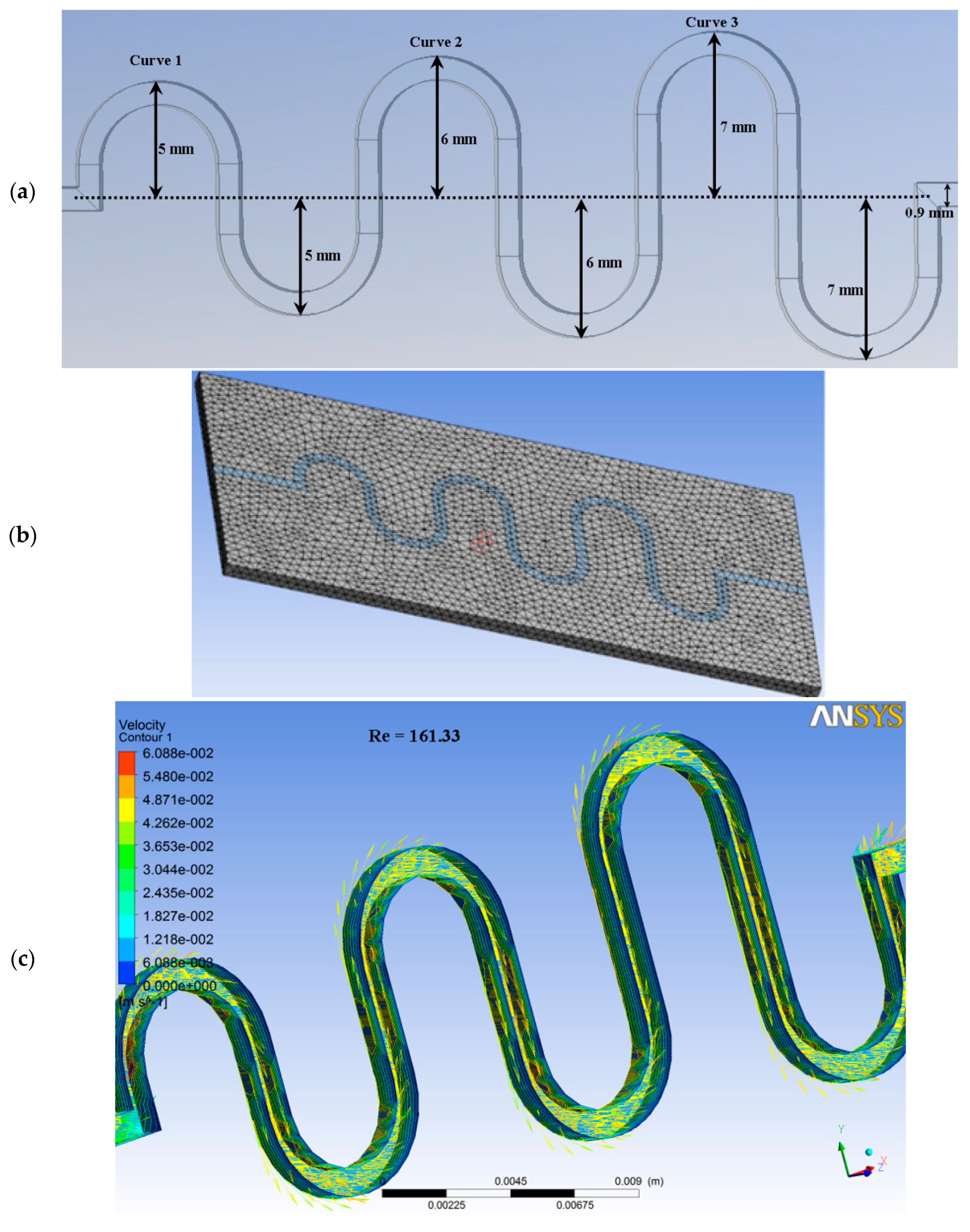
| Reynolds Number = 160 | Reynolds Number = 161.33 | Reynolds Number = 164.88 |
| Flow Rate = 5.11 (0.1 nL/s) | Flow Rate = 6.0 (0.1 nL/s) | Flow Rate = 5.8 (0.1 nL/s) |
| Velocity = 4.55 (cm/s) | Velocity = 6.088 (cm/s) | Velocity = 5.8 (cm/s) |
© 2017 by the authors. Licensee MDPI, Basel, Switzerland. This article is an open access article distributed under the terms and conditions of the Creative Commons Attribution (CC BY) license (http://creativecommons.org/licenses/by/4.0/).
Share and Cite
Afzal, M.J.; Tayyaba, S.; Ashraf, M.W.; Hossain, M.K.; Uddin, M.J.; Afzulpurkar, N. Simulation, Fabrication and Analysis of Silver Based Ascending Sinusoidal Microchannel (ASMC) for Implant of Varicose Veins. Micromachines 2017, 8, 278. https://doi.org/10.3390/mi8090278
Afzal MJ, Tayyaba S, Ashraf MW, Hossain MK, Uddin MJ, Afzulpurkar N. Simulation, Fabrication and Analysis of Silver Based Ascending Sinusoidal Microchannel (ASMC) for Implant of Varicose Veins. Micromachines. 2017; 8(9):278. https://doi.org/10.3390/mi8090278
Chicago/Turabian StyleAfzal, Muhammad Javaid, Shahzadi Tayyaba, Muhammad Waseem Ashraf, M. Khalid Hossain, M. Jalal Uddin, and Nitin Afzulpurkar. 2017. "Simulation, Fabrication and Analysis of Silver Based Ascending Sinusoidal Microchannel (ASMC) for Implant of Varicose Veins" Micromachines 8, no. 9: 278. https://doi.org/10.3390/mi8090278