Design and Simulation of A Novel Piezoelectric AlN-Si Cantilever Gyroscope
by
 ,
,
Jian Yang
1,2,3 ,
,
Chaowei Si
1,*,
Fan Yang
1,2,
Guowei Han
1,
Jin Ning
1,3,4,
Fuhua Yang
1,2 and
Xiaodong Wang
1,5,* 1
Institute of Semiconductors, Chinese Academy of Sciences, Beijing 100083, China
2
College of Materials Science and Opto-Electronic Technology, University of Chinese Academy of Sciences, Beijing 100049, China
3
State Key Laboratory of Transducer Technology, Chinese Academy of Sciences, Beijing 100083, China
4
School of Electronic, Electrical and Communication Engineering, University of Chinese Academy of Sciences, Beijing 100049, China
5
School of Microelectronics, University of Chinese Academy of Sciences, Beijing 100049, China
*
Authors to whom correspondence should be addressed.
Micromachines 2018, 9(2), 81; https://doi.org/10.3390/mi9020081
Submission received: 28 December 2017
/
Revised: 11 February 2018
/
Accepted: 13 February 2018
/
Published: 15 February 2018
(This article belongs to the Special Issue Piezoelectric MEMS)
Abstract
:A novel design of piezoelectric aluminum nitride (AlN)-Si composite cantilever gyroscope is proposed in this paper. The cantilever is stimulated to oscillate in plane by two inverse voltages which are applied on the two paralleled drive electrodes, respectively. The whole working principles are deduced, which based on the piezoelectric equation and elastic vibration equation. In this work, a cantilever gyroscope has been simulated and optimized by COMSOL Multiphysics 5.2a. The drive mode frequency is 87.422 kHz, and the sense mode frequency is 87.414 kHz. The theoretical sensitivity of this gyroscope is 0.145 pm/◦/s. This gyroscope has a small size and simple structure. It will be a better choice for the consumer electronics.
1. Introduction
Microelectromechanical systems (MEMS) gyroscopes are core inertial sensors. They are widely used in smartphones, unmanned aerial vehicles (UAV), automotive electronics, or other consumer goods [1]. In recent years, aluminum nitride (AlN) piezoelectric gyroscopes become a new research trend. The AlN gyroscopes can be categorized into two main types: (1) thin-film AlN gyroscopes and (2) bulk acoustic wave (BAW) AlN-on-Si gyroscopes. The thin-film AlN gyroscopes have traditional structures: beams and proof masses. The AlN thin-film gyroscope relies on bending vibration of beams. The drive mode is simulated by voltages and the Coriolis force is detected through piezoelectric charge. While, the BAW AlN-on-Si gyroscopes are made up of an AlN film on silicon substrate with a specific geometry. Two degenerate bulk acoustic wave modes of the AlN film, which are orthogonal to each other, are used as the drive mode and sense mode, respectively.
The Albert P. Pisano’s group, which comes from the University of California, focuses on the thin-film AlN gyroscopes [2,3,4]. The structure contains three layers: the AlN layer and the bottom/top electrode layers. The thickness of AlN is 2 μm. These gyroscopes have a high efficiency of electromechanical transduction. However, a near zero stress AlN film is needed. It is difficult for the AlN deposition process, and the robustness of this gyroscope is another serious problem. Farrokh Ayazi’s group, which is from the Georgia Institute of Technology, focuses on the BAW AlN-on-Si gyroscopes [5,6,7]. From 2013 to the present, many different kinds of BAW gyroscopes have been researched and optimized. These gyroscopes have a relatively high frequency (3.1–11 MHz) and perfect immunity to shock and vibration. However, a high frequency will lead to a reduction of response amplitude. The sensitivity will decrease. Besides, the size of these BAW gyroscopes are very large.
Considering the characteristics of the two AlN gyroscopes, a novel AlN-Si composite cantilever gyroscope is proposed in this paper. Based on the piezoelectric effect of AlN, the cantilever will be excited to bend in-plane. The working frequency is 87 kHz, which is lower than the frequency of BAW AlN-on-Si gyroscopes. This will benefit the sensitivity. This gyroscope has a small size and simple structure. Analysis and simulation of this piezoelectric gyroscope has been carried out and reported on in this paper.
2. Working Principles
2.1. Working Principles of Drive Mode
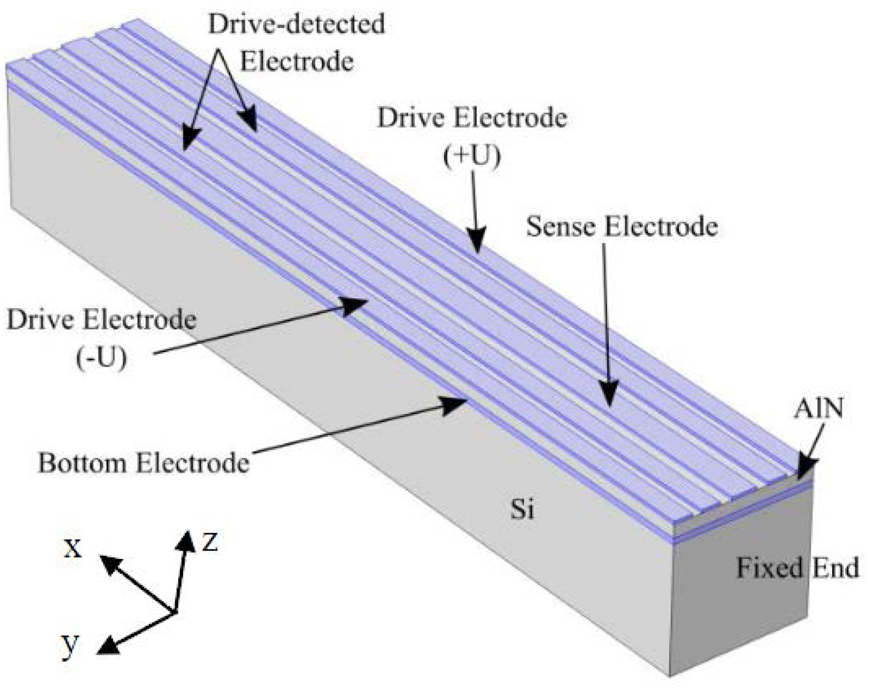
The schematic of AlN-Si composite cantilever gyroscope is shown in Figure 1. It contains four layers. The bottom electrode layer is Mo, connecting the ground in electric field. The top layer is Al, divided into five parts. The five electrodes include two drive electrodes, two drive-detected electrodes, and one sense electrode. In this gyroscope, AlN layer works as drive function for the composite cantilever. Inverse voltages are applied on two drive electrodes respectively, as shown in Figure 1 and Figure 2. The drive-detected electrodes are used to detect the drive signal. The purpose is to stabilize both magnitude and frequency of the drive signal. Based on the piezoelectric effect of AlN, the two inverse voltages will excite two inverse stresses (±σ)—the compressive stress and tensile stress. The direction of the stresses are along with the length of cantilever. They will form a couple stress. The formula of σ has been deduced as shown in Equation (1).
where EAlN is the Young’s modulus of AlN, dAlN is the thickness of AlN, U is the sinusoidal drive voltage, ω is the angular frequency of drive voltage, and d31 is the piezoelectric coefficient of AlN. According to the references, d31 = −2.6 pm/V [8,9].
This couple stress will drive the AlN-Si composite cantilever to bend in-plane, as shown in Figure 2. The bending moment M is given by Equation (2). Where W represents the width of cantilever and Wdri represents the width of drive electrodes.
The deformation of cantilever satisfies the approximately differential equation of flexural curve of Equation (3). By solving the Equation (3), the displacement function y(x,t) can be deduced as shown in Equation (4). Where EIy denotes the flexural rigidity of the composite cantilever in y direction. EAl, EMo, and ESi are the Young’s modulus of Al, Mo, and Si respectively; and dAl, dMo, and dSi are the thickness of Al, Mo, and Si respectively. The x axial is parallel to the length direction of cantilever. x is the position, belonging to [0,L]. All the parameters are shown in Table 1.
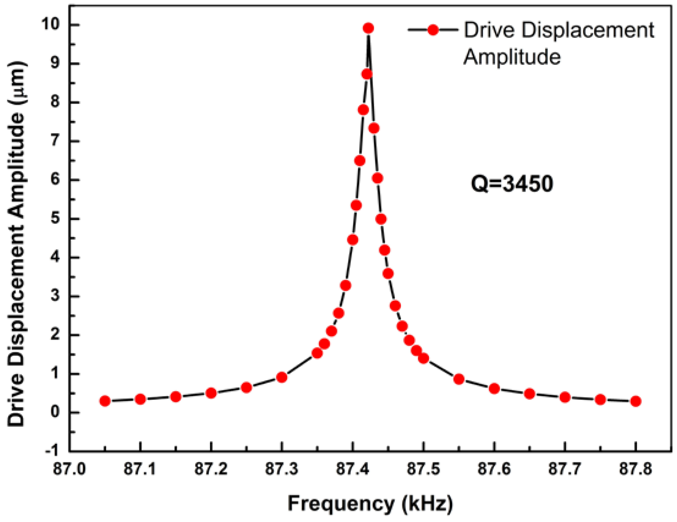
Plugging the values into Equation (4), the theoretical value of maximum displacement ymax = y(L,) = 2.920 nm can be calculated. Meanwhile, the same cantilever model has been designed and simulated by COMSOL Multiphysics 5.2a (COMSOL Inc., Stockholm, Sweden). A stationary study has been simulated. The maximum stationary displacement of simulation value is ys-max = 2.878 nm, as shown in Figure 3. Comparing the theoretical value to the simulation one, an error ratio 1.5% can be calculated. This proves that the deduction of working principles is logical and accurate. To further research the resonant properties, a frequency domain study has been done. The maximum resonant displacement is 9.92 μm, and the quality factor is 3450, as shown in Figure 4.
2.2. Working Principles of Sense Mode
This gyroscope can detect an angular rate which is along the length direction of cantilever. When an x axial angular rate Ω is applied, the cantilever will be driven to bend out-plane by Coriolis force FC(x,t). The FC(x,t) formula can be deduced as shown in Equation (5). The ρall is a linear density of the composite cantilever. C0 represents the constant coefficient of y(x,t). The direction of FC(x,t) is z-axial.
By solving the approximately differential equation of flexural curve in z direction-Equation (6), a displacement function z(x,t) can be deduced. The function z(x,t) is shown in Equation (7). EIz is the flexural rigidity of the composite cantilever in z direction. The function z(x,t) is the displacement of sense mode. Therefore, a linear relation between z and Ω can be gotten from Equation (7). The maximum coefficient of z(Ω) is the sensitivity of this gyroscope.
3. Design of AlN-Si Composite Cantilever Gyroscope
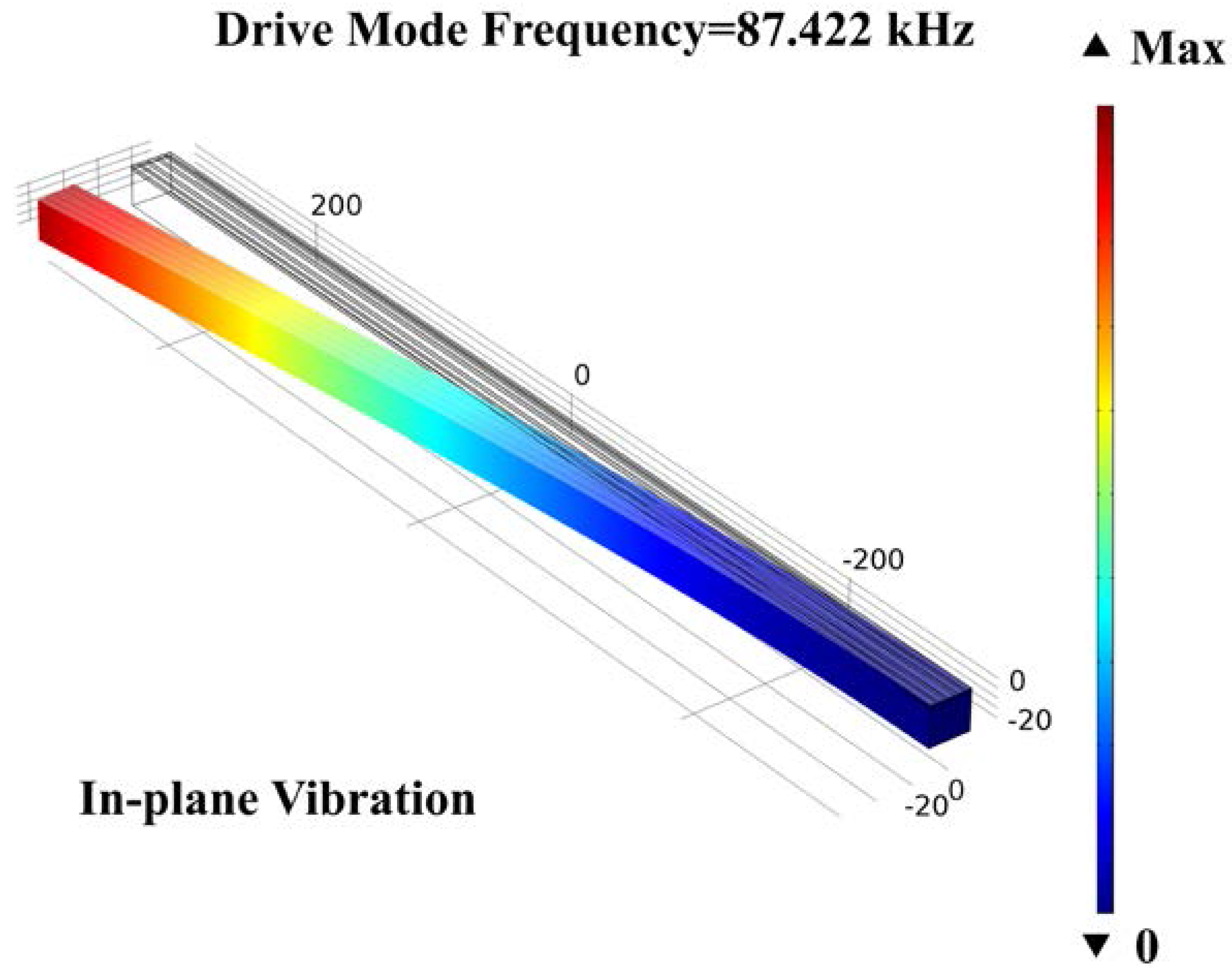
The main structure of this gyroscope is shown in Figure 1. The sizes of AlN-Si composite cantilever are designed and optimized by COMSOL Multiphysics. To realize the mode matching, the parametric sweep function was used. The valve of the cantilever width has been swept from 20 μm to 25 μm, with a step of 0.01 μm. When the value is 22.87 μm, the frequencies of drive mode and sense mode are nearly equal. All the values are shown in Table 2. The simulation result of drive mode frequency is 87.422 kHz, and the sense mode frequency is 87.414 kHz. The mode shapes are shown in Figure 5 and Figure 6, respectively.
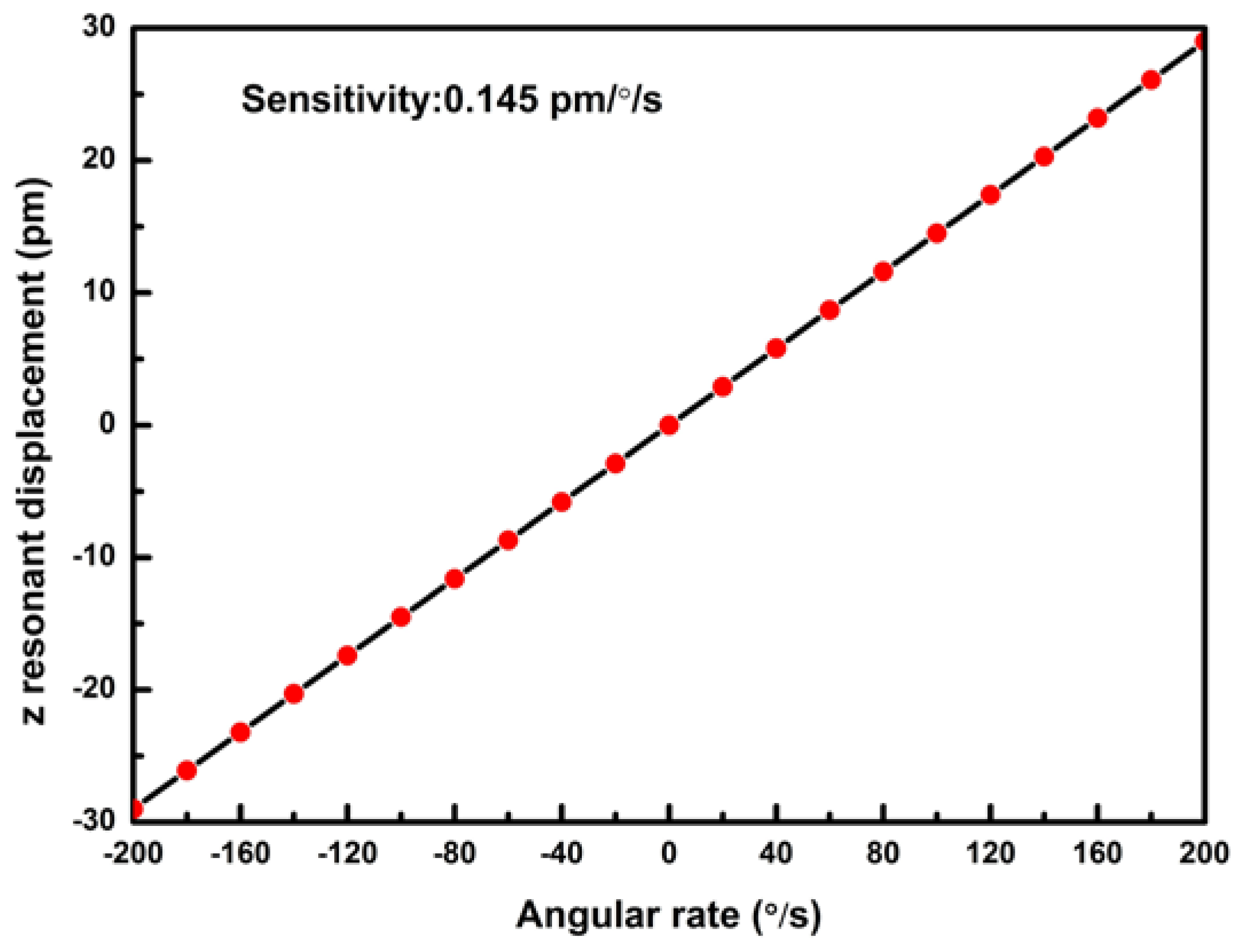
The quality factors of this gyroscope are assumed to be Qdrive = 3000 and Qsense = 3000, respectively. The maximum resonant displacement zres(L,) is shown in Equation (8). Therefore, the sensitivity of this gyroscope is 0.145 pm/◦/s, as shown in Figure 7.
4. Conclusions
The AlN-Si composite cantilever gyroscope is based on the novel electrode design and working principles. Because of the piezoelectric effect of AlN, an in-plane movement has been stimulated by two inverse voltages. The AlN-Si composite cantilever gyroscope has been designed with 87.422 kHz drive frequency and 87.414 kHz sense frequency. The mode-matching has been realized by optimizing the width of the cantilever. This gyroscope has a small size, simple structure, and lower requirements for the processing of AlN film. Hence, this cantilever gyroscope shows great potential in the piezoelectric research and consumer electronics fields.
Acknowledgments
The authors gratefully acknowledge Chinese National Science Foundation (contracts No. 61504130, no. 61704165, and no. 61474115).
Author Contributions
Jian Yang and Chaowei Si conceived and designed the MEMS gyroscope structure. Jian Yang performed the simulation and wrote the paper. Fan Yang, Guowei Han, Jin Ning, Fuhua Yang, and Xiaodong Wang revised the paper.
Conflicts of Interest
The authors declare no conflict of interest.
References
- Sara, S.; Naser, E. Activity recognition using fusion of low-cost sensors on a smartphone for mobile navigation application. Micromachines 2015, 6, 1100–1134. [Google Scholar] [CrossRef]
- Gabriele, V. MEMS Aluminum Nitride Technology for Inertial Sensors. Doctoral Thesis, University of California, Berkeley, CA, USA, 2011. [Google Scholar]
- Fabian, T.G.; Gabriele, V.; Igor, I.I. Novel thin-film piezoelectric aluminum nitride rate gyroscope. In Proceedings of the 2012 IEEE International Ultrasonics Symposium, Dresden, Germany, 7–10 October 2012; pp. 1067–1070. [Google Scholar]
- Fabian, G.; Kirti, M.; Kansho, Y. Experimentally validated aluminum nitride based pressure, temperature and 3-axis acceleration sensors integrated on a single chip. In Proceedings of the 2014 IEEE 27th International Conference on Micro Electro Mechanical Systems, San Francisco, CA, USA, 26–30 January 2014; pp. 729–732. [Google Scholar]
- Roozbeh, T.; Mojtaba, H.S.; Farrokh, A. High-frequency AlN-on-silicon resonant square gyroscopes. J. Microelectromech. Syst. 2013, 22, 1007–1009. [Google Scholar]
- Mojtaba, H.S.; Arashk, N.S.; Roozbeh, T. A dynamically mode-matched piezoelectrically transduced high-frequency flexural disk gyroscope. In Proceedings of the 2015 28th IEEE International Conference on Micro Electro Mechanical Systems (MEMS), Estoril, Portugal, 18–22 January 2015; pp. 789–792. [Google Scholar]
- Mojtaba, H.S.; Arashk, N.S.; Farrokh, A. Eigenmode operation as a quadrature error cancellation technique for piezoelectric resonant gyroscopes. In Proceedings of the 2017 IEEE 30th International Conference on Micro Electro Mechanical Systems (MEMS), Las Vegas, NV, USA, 22–26 January 2017; pp. 1107–1110. [Google Scholar]
- Hernando, J.; Sanchez-Rojas, J.L.; Gonzalez-Castilla, S. Simulation and laser vibrometry characterization of piezoelectric AIN thin films. J. Appl. Phys. 2008, 104, 053502-1–053502-9. [Google Scholar] [CrossRef] [Green Version]
- Martin, F.; Muralt, P.; Dubois, M.A. Thickness dependence of the properties of highly c-axis textured AlN thin films. J. Vac. Sci. Technol. A Vac. Surf. Films 2004, 22, 361–365. [Google Scholar] [CrossRef]
Figure 1.
The structure of aluminum nitride (AlN)-Si composite cantilever gyroscope.

Figure 2.
The schematic of in-plane vibration of cantilever.
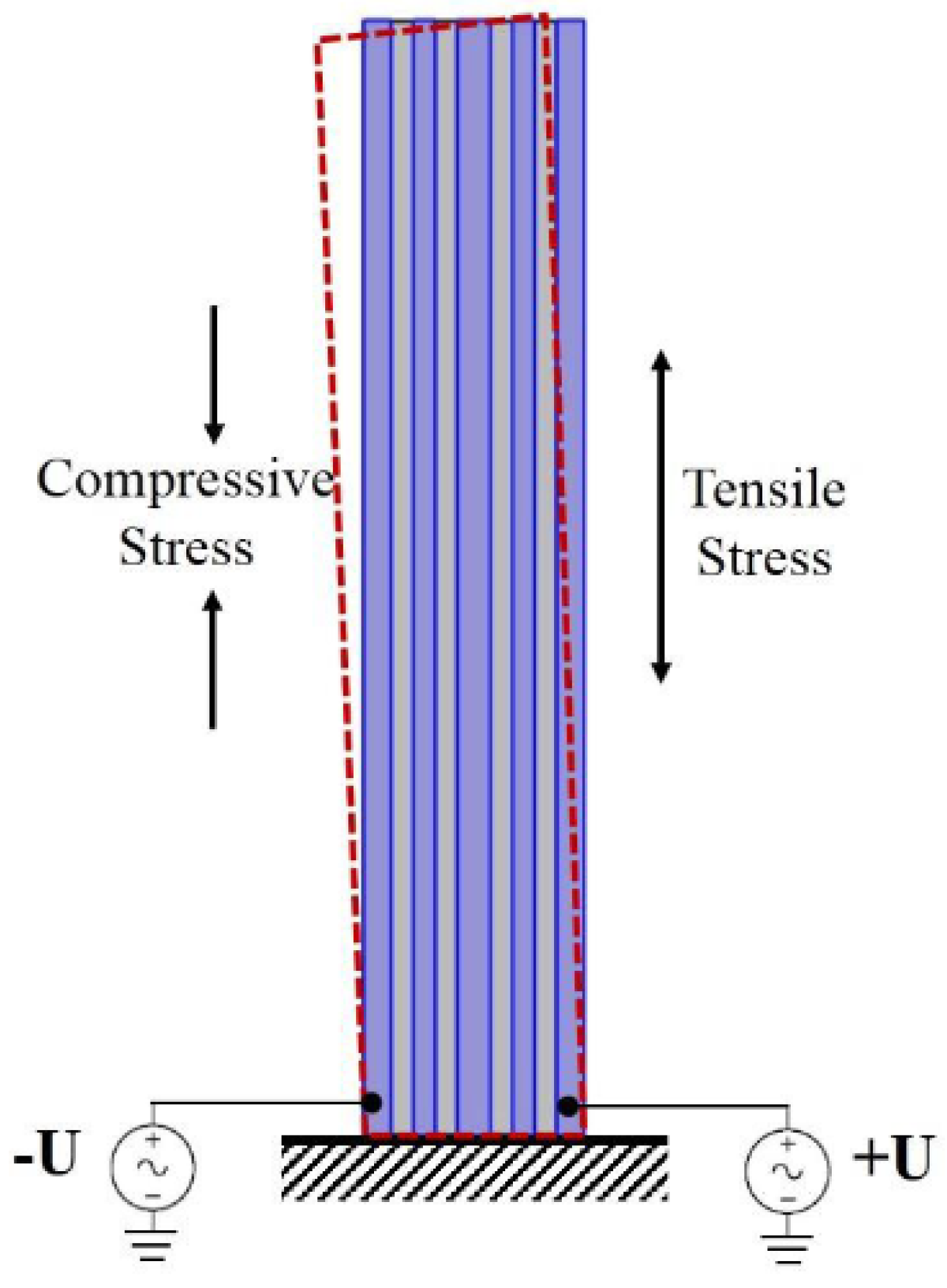
Figure 3.
Displacement simulation of AlN-Si composite cantilever under 1 V drive voltages, stationary study.
Figure 3.
Displacement simulation of AlN-Si composite cantilever under 1 V drive voltages, stationary study.
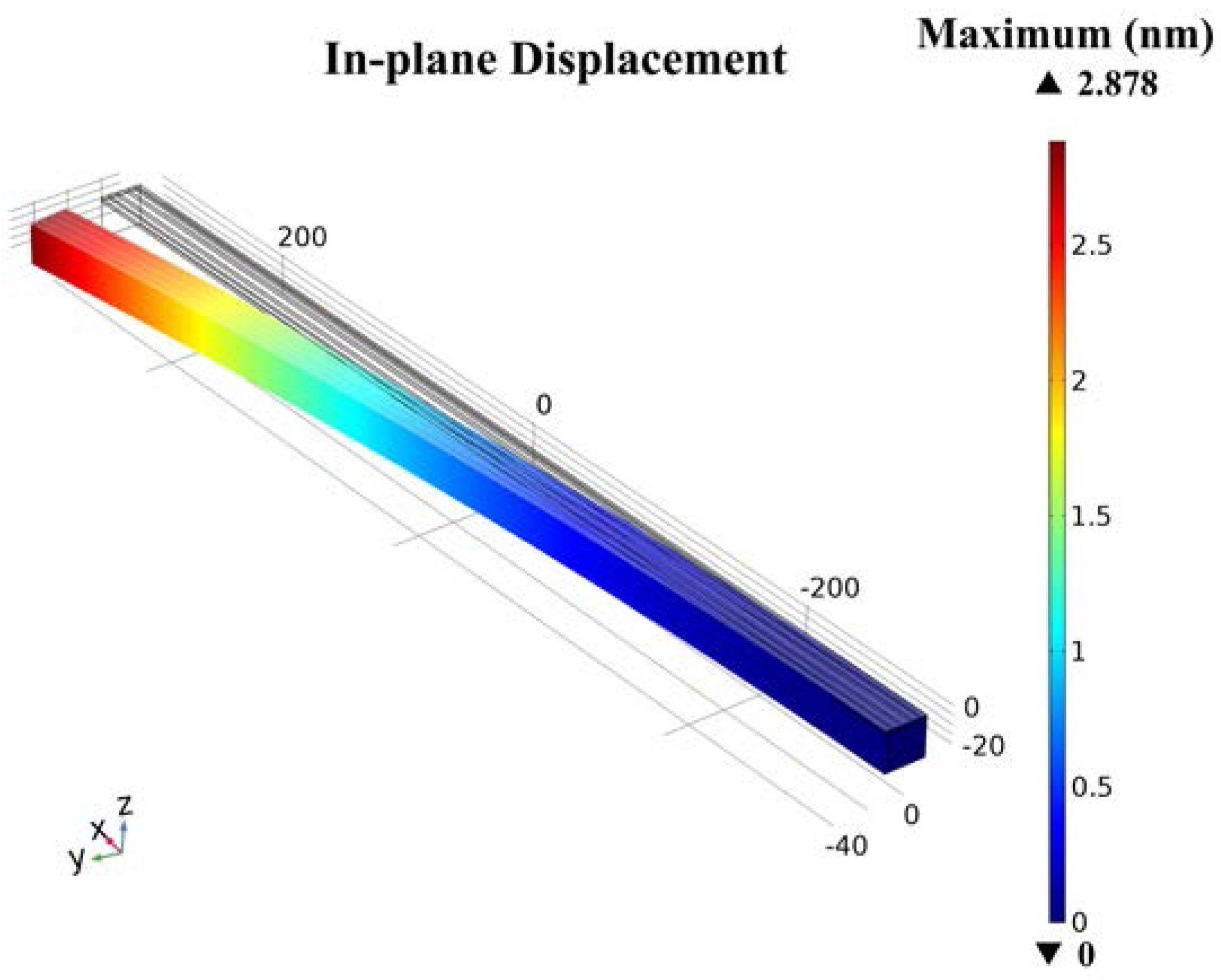
Figure 4.
The resonant displacement amplitude of drive mode, frequency domain study.

Figure 5.
The drive mode simulation of the cantilever gyroscope.

Figure 6.
The sense mode simulation of the cantilever gyroscope.
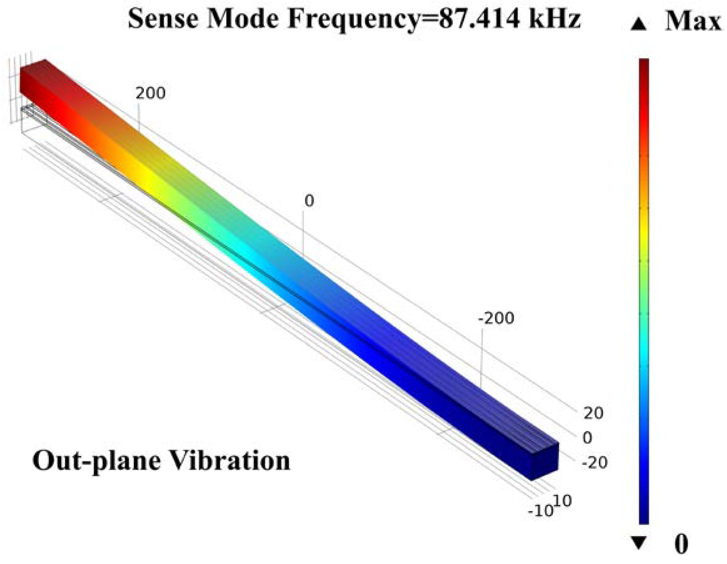
Figure 7.
Theoretical sensitivity of the gyroscope—the resonant displacement of z-axis vs. angular rate Ω.
Figure 7.
Theoretical sensitivity of the gyroscope—the resonant displacement of z-axis vs. angular rate Ω.

Table 1.
Parameters of aluminum nitride (AlN)-Si composite cantilever for calculation and simulation.
Table 1.
Parameters of aluminum nitride (AlN)-Si composite cantilever for calculation and simulation.
| Names | Parameters | Values | Units |
|---|---|---|---|
| EAlN | Young’s modulus | 410 | GPa |
| ESi | Young’s modulus | 160 | GPa |
| EMo | Young’s modulus | 312 | GPa |
| EAl | Young’s modulus | 70 | GPa |
| dAlN | Thickness | 1.5 | μm |
| dSi | Thickness | 20 | μm |
| dMo | Thickness | 0.3 | μm |
| dAl | Thickness | 0.3 | μm |
| d31 | Piezoelectric coefficient | −2.6 | pm/V |
| L | Length of cantilever | 600 | μm |
| W | Width of cantilever | 22.87 | μm |
| Wdri | Width of drive electrode | 3 | μm |
| U0 | Amplitude | 1 | V |
Table 2.
Sizes of AlN-Si composite cantilever gyroscope.
| Names | Parameters | Values | Units |
|---|---|---|---|
| L | Length of cantilever | 600 | μm |
| W | Width of cantilever | 22.87 | μm |
| Wdri | Width of drive electrode | 3 | μm |
| Wdri_det | Width of drive-detected electrode | 3 | μm |
| Wsen | Width of sense electrode | 4 | μm |
| dAlN | Thickness | 1.5 | μm |
| dSi | Thickness | 20 | μm |
| dMo | Thickness | 0.3 | μm |
| dAl | Thickness | 0.3 | μm |
© 2018 by the authors. Licensee MDPI, Basel, Switzerland. This article is an open access article distributed under the terms and conditions of the Creative Commons Attribution (CC BY) license (http://creativecommons.org/licenses/by/4.0/).
Share and Cite
MDPI and ACS Style
Yang, J.; Si, C.; Yang, F.; Han, G.; Ning, J.; Yang, F.; Wang, X. Design and Simulation of A Novel Piezoelectric AlN-Si Cantilever Gyroscope. Micromachines 2018, 9, 81. https://doi.org/10.3390/mi9020081
AMA Style
Yang J, Si C, Yang F, Han G, Ning J, Yang F, Wang X. Design and Simulation of A Novel Piezoelectric AlN-Si Cantilever Gyroscope. Micromachines. 2018; 9(2):81. https://doi.org/10.3390/mi9020081
Chicago/Turabian StyleYang, Jian, Chaowei Si, Fan Yang, Guowei Han, Jin Ning, Fuhua Yang, and Xiaodong Wang. 2018. "Design and Simulation of A Novel Piezoelectric AlN-Si Cantilever Gyroscope" Micromachines 9, no. 2: 81. https://doi.org/10.3390/mi9020081
Note that from the first issue of 2016, this journal uses article numbers instead of page numbers. See further details here.