Method of Measuring the Mismatch of Parasitic Capacitance in MEMS Accelerometer Based on Regulating Electrostatic Stiffness

1
Science and Technology on Reliability Physics and Application of Electronic Component Laboratory, No.5 Electronics Research Institute of the Ministry of Industry and Information Technology, Guangzhou 510610, China
2
College of Physics and Optoelectronic Engineering, Guangdong University of Technology, Guangzhou 510006, China
*
Author to whom correspondence should be addressed.
Micromachines 2018, 9(3), 128; https://doi.org/10.3390/mi9030128
Submission received: 29 January 2018
/
Revised: 25 February 2018
/
Accepted: 2 March 2018
/
Published: 15 March 2018
(This article belongs to the Special Issue MEMS Accelerometers)
Abstract
:For the MEMS capacitive accelerometer, parasitic capacitance is a serious problem. Its mismatch will deteriorate the performance of accelerometer. Obtaining the mismatch of the parasitic capacitance precisely is helpful for improving the performance of bias and scale. Currently, the method of measuring the mismatch is limited in the direct measuring using the instrument. This traditional method has low accuracy for it would lead in extra parasitic capacitive and have other problems. This paper presents a novel method based on the mechanism of a closed-loop accelerometer. The strongly linear relationship between the output of electric force and the square of pre-load voltage is obtained through theoretical derivation and validated by experiment. Based on this relationship, the mismatch of parasitic capacitance can be obtained precisely through regulating electrostatic stiffness without other equipment. The results can be applied in the design of decreasing the mismatch and electrical adjusting for eliminating the influence of the mismatch.
1. Introduction
An accelerometer is a key device in inertial navigation and control systems for measuring the acceleration information of a carrier. With the progress of MEMS technology, the MEMS accelerometer has been rapidly developed and is widely used in military, industry, medicine, and consumer electronics fields for its small volume, light weight, small power consumption, and low cost. Among MEMS accelerometers, the closed-loop capacitive accelerometer based on electrostatic force balance is an important form for its relatively good performance [1,2].
The MEMS capacitive accelerometer measures the acceleration through electrically detecting the changed differential capacitance of sensor caused by the movement of proof-mass under acceleration. As is known to all, parasitic capacitance is a serious problem in MEMS capacitive accelerometers [3,4,5]. Its mismatch between electrodes including in the sensor, package, and circuit would produce an offset and deteriorate the performance of bias and scale. The mismatch of effective capacitance due to process variation during sensor fabrication can be eliminated by the closed-loop system, but the mismatch of parasitic capacitance remains. Some research has been carried out for eliminating the influence of the parasitic capacitance [6,7,8], but these methods are either unsolved completely or lead to extra questions. Reducing the mismatch of parasitic capacitance is more direct and effective, and another solution is compensating the mismatch through electrical adjusting or adding an extra capacitor which is widely used [9,10]. Either reducing or compensating the mismatch of parasitic capacitance should be measured accurately.
Currently, the method of measuring the parasitic capacitance is limited in the direct measuring using the instrument or the capacitive measuring circuit [11,12]. This method has low accuracy for it would lead to extra parasitic capacitance and the measuring result is the state of off-power, moreover, some equivalent parasitic capacitance cannot be obtained and it cannot be implemented in some occasions. This paper proposes a novel method of measuring the mismatch of parasitic capacitance in MEMS accelerometer based on the mechanism of a closed-loop system. Through regulating the electrostatic negative stiffness and obtaining the curve between the output of electric force and the square of pre-load voltage, the mismatch can be obtained according to the coefficient of linear fitting. This method can be applied in the design for reducing the mismatch and electrical adjusting for eliminating the influence of mismatch, and the research for the characteristics of the mismatch influenced by the temperature and the self-calibrating technique of eliminating the mismatch can be further studied with this method.
2. Method of Measuring the Mismatch of Parasitic Capacitance
2.1. Influence of Parasitic Capacitance
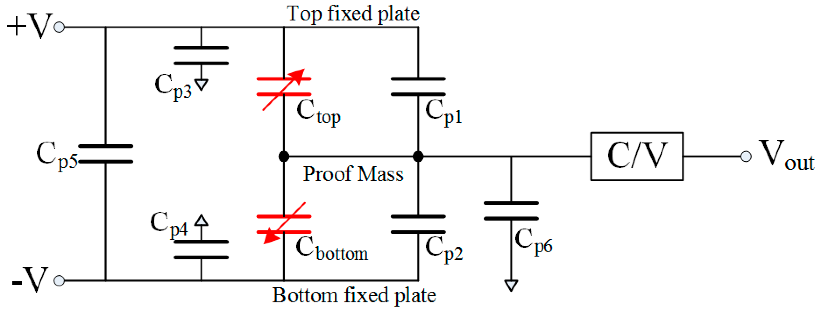
Figure 1 shows the schematic of effective and parasitic capacitances in MEMS capacitive accelerometer interfaced with a C/V converting circuit. Obviously, there are several parasitic capacitances and the mismatch of parasitic capacitances ΔCm1 between Cp1 and Cp2—including in the sensor, package, and circuit—will confuse the differential effective capacitances ΔC between Ctop and Cbottom that would produce an offset. The mismatch ΔCm2 between Cp3 and Cp4 will also have an influence on the output. Besides, the parasitic capacitances, Cp5 and Cp6, can affect the influence of ΔCm1 and ΔCm2 on the output.
Generally, the sensitivity of effective capacitance is about 100 fF/g or even smaller and the mismatch of parasitic capacitance can be up to 100 fF that will result in an offset of 1 g. This large offset would severely deteriorate the performance of the accelerometer. Therefore, it is necessary to study the mismatch and do some work for reducing the influence. Measuring the mismatch accurately is a basic step. Though there are many discrete parasitic capacitances, we only need to obtain the total equivalent mismatch.
2.2. Theory of Measuring the Mismatch
In the closed-loop system of a MEMS capacitance accelerometer, there is electrostatic force between fixed plates and proof mass that balances the inertial force caused by acceleration [13], and the proof mass is not at the geometrical center for the mismatch of parasitic capacitance. Figure 2 shows a working diagram of the sensor.
Considering the process variation and parasitic capacitance, the electrostatic force of the proof mass is:
where and are the relative and absolute dielectric constant respectively, is the overlapped area of capacitance, is the modulated voltage, is the feedback voltage, is the pre-load voltage, is the average gap between electrodes, is the gap deviation due to process variation, and is the bending value of the beam due to the mismatch of effective and parasitic capacitance.
In general, and are far smaller than , and then, Equation (1) can be simplified to:
where the bending value consists of brought by the mismatch of effective capacitance and brought by the mismatch of parasitic capacitance, so . Substituting this equation to Equation (2), the electrostatic force can be expressed as:
where is called electrostatic stiffness.
In the closed-loop system, there is the force balance for the proof mass:
where is the stiffness of the beam, is the inertial mass of the proof mass, is the external acceleration, and is the residual stress. Replacing Equation (3) into Equation (4), the formula of force balance can be expressed as:
where . When the input acceleration is unchanged, the parameter can be considered as a fixed value. When the input acceleration and offset are small, is far smaller than , so Equation (5) can be simplified to:
For the digital acquisition system, the left portion in Equation (6) can be transformed to where is digital output which unit is LSB, is the scale of accelerometer which unit is LSB/g and is local gravity acceleration. Then, Equation (6) can be transformed to:
Equation (7) can be transformed to:
where is dependent variable, is independent variable, is linear coefficient and is intercept which is a fixed value.
Equation (8) shows that the relationship between output of electrostatic force and the square of pre-load voltage is linear. Thus, we can make a curve with as y-axis and as x-axis, and then, a linear fitting of the curve is made. Lastly, the mismatch of the parasitic capacitance can be obtained from the linear coefficient through the equation:
where can be calculated through the obtained scale of the closed-loop system. Meanwhile, we can get the offset and the deviation from geometrical center due to the mismatch of parasitic capacitance.
3. Measurement Results and Discussion
Measuring tests have been done with closed-loop MEMS accelerometer to verify this novel method and two applications with this method are present. The measuring work were implemented on a printed circuit board (PCB) with discrete component, interfaced with a packaged sensor using ceramic shell and bond wire. The senor is fabricated with bulk silicon process and the structure is comb finger. The control system is achieved by analogue circuit and the analogue output is digitally acquired through Analog to Digital Convert (ADC) and Field Programmable Gate Array (FPGA) chip. The full-scale range of the accelerometer is 30 g, and the noise is 10μg/√Hz. In this system, the parasitic capacitances originate from the sensor, the ceramic shell, the bond wire and the PCB circuit. In our designed accelerometer, this mismatch commonly leads in an offset of several hundred mg that severely deteriorates the performance of accelerometer.
3.1. Measurement Results
3.1.1. Verification Experiment and Results
In the verification experiment, the accelerometer is placed on the marble platform and the input acceleration is about 0 g which purpose is to make the external acceleration stable and the output very small. This step can improve the accuracy of the measurement. Because the pre-load voltage goes through voltage follower and resistance, and then reaches the node of proof-mass, so, the pre-load voltage does not directly connect to this C/V node. We draw out a line from the node of pre-load voltage that did not change the output. Then, the pre-loaded voltage of the accelerometer is changed, and the scale is tested through turning the accelerometer. The changed pre-loaded voltage, the digital output and the scale are record. Table 1 contains the measuring data with different pre-loaded voltage.
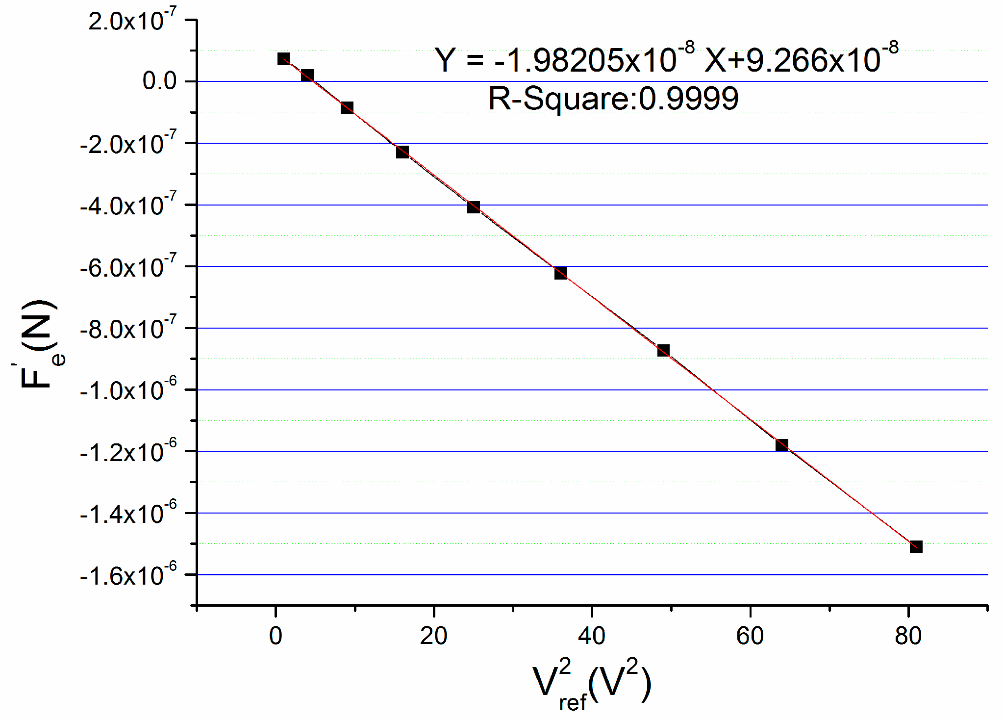
Using these recorded data, we make a figure by taking as x-axis and as y-axis as shown in Figure 3, and a linear fitting of the curve is made.
The R2 of the linear fitting is 0.9999 which shows highly linear correlation between and . The strong linear relationship validates the theory of formula deduction. From the linear fitting formula, the linear coefficient can be obtained which is −1.98205 × 10⁻⁸. Through calculation according to this number, the bending value of the beam owing to the mismatch of parasitic capacitance which is also the deviation from the geometrical center is −13.48 nm. It should be noted that the bending value of the beam is a vector. That is to say it can be positive or negative. The bending direction of the beam depends on the sum of and , and the minus sign of this indicates that the beam bends to the bottom plate, owing to the mismatch of parasitic capacitance. Correspondingly, the mismatch of parasitic capacitance is −69.372 fF and the offset caused by the mismatch is 219 mg.
3.1.2. Applications and Results
The charge amplifier and diode ring are the common used C/V converting circuit. Because the charge amplifier is based on current measurement, the parasitic capacitance Cp3 and Cp4 in figure1 has little influence on the output of charge amplifier. However, in our design the diode ring detecting circuit is adopted for its simple structure. In diode ring detecting circuit, the principle of C/V converting is based on charge-discharge of capacitance. The capacitance Cp3 and Cp4 would affect the charge–discharge process of demodulating capacitance, so, it has an effect on the output. We carried out an experimental test to study the influence on output of capacitance to ground (GND) previously. A 1 pF difference between Cp3 and Cp4 was made in MEMS accelerometer using diode ring detecting circuit and a change of 0.5 g on output was observed, so it is necessary to study the influence of the parasitic capacitance between the fixed plate and GND. It should be noted that the effect of this equivalent mismatch on output is not equal to the effective differential capacitance, so its equivalent mismatch cannot be measured using the direct measuring method. The experiment for measuring the equivalent mismatch of the parasitic capacitance between the fixed plate and GND is carried out.
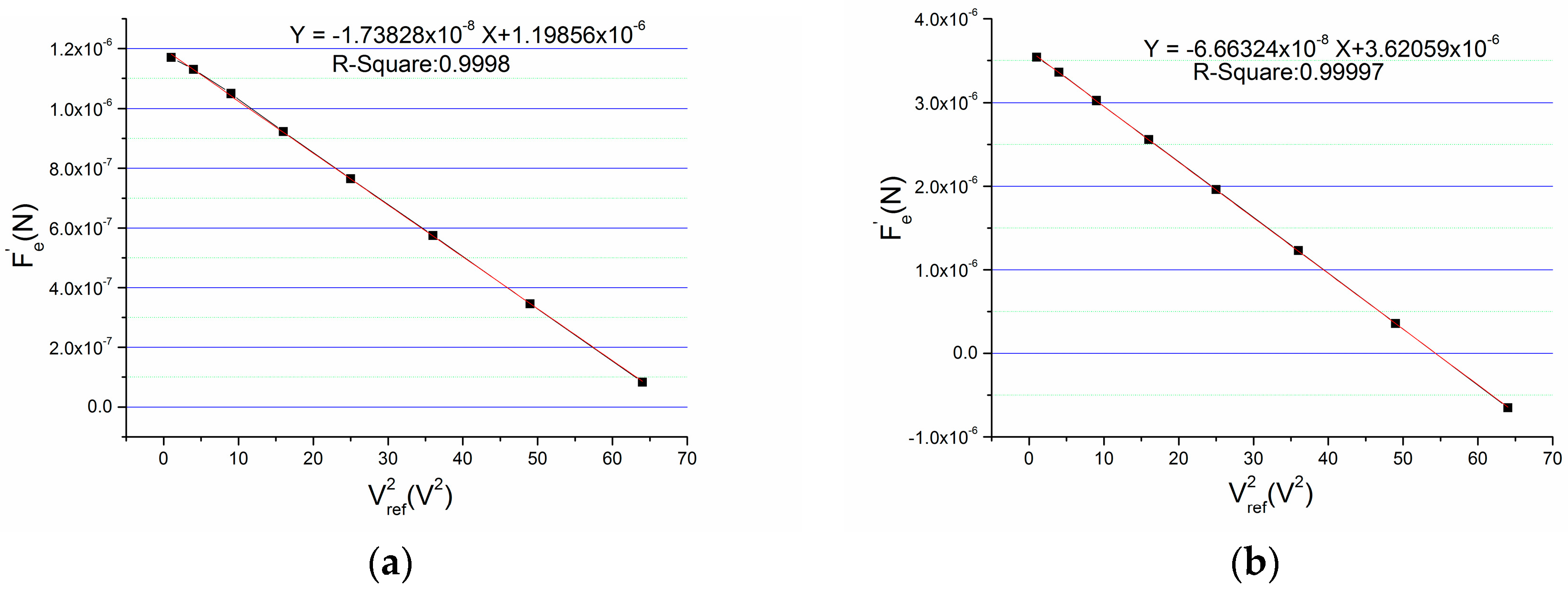
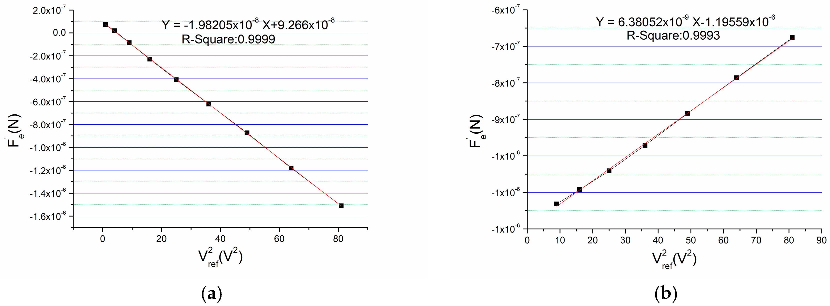
A chip capacitor of 1 pF is intentionally added between the top fixed plate and GND. Because this operation changes the bias of accelerometer which is equivalent to changing the equivalent mismatch. Then, the total equivalent mismatch is measured using this novel method before and after adding this capacitor. Figure 4 is the testing results which show the influence of this mismatch.
The linear coefficient after adding the chip capacitor is much bigger than the one of initial state that indicates the parasitic capacitance between the fixed plate and GND can seriously affect the output. Through calculating, the initial mismatch of the accelerometer is −60.840 fF and the mismatch after adding the 1 pF capacitance is −233.213 fF. So, the equivalent mismatch of the 1 pF capacitance between the fixed plate and GND is 172.373 fF.
Another application using this method is improving the design of circuit to reduce the mismatch of parasitic capacitive. Table 2 shows the mismatch of parasitic capacitive for different sensors on same circuit board. For these six sensors, the average bending value is −11.0 nm and the average mismatch is −56.44 fF, which causes an offset of 179 mg. It can be seen that the values of the mismatch are near that indicates the mismatch is mainly from the circuit board for the mismatch of different sensors would have large discreteness.
The design of the circuit should be improved to reduce the mismatch of parasitic capacitance on the circuit board. An improved circuit was fabricated and the mismatch is measured with the same sensor welded on different circuit boards. Figure 5 is the contrast of mismatch on different circuit boards. The mismatch of parasitic capacitance is −69.372 fF on the before-optimization circuit board, and it is +22.332 fF on the after-optimization circuit board. It can be seen that through optimizing the circuit design, the mismatch of parasitic capacitance is reduced by 69% and the sign of the mismatch is changed.
3.2. Discussion
The linear relationship between output of electrostatic force and the square of pre-load voltage is validated by the experiment. In an ideal system with no mismatch, the force is a fixed value for the feedback and pre-load voltage are changed at inverse proportions. However, due to the existence of the mismatch of parasitic capacitance in real system, the force will be changed in proportion to following the changed force when regulating the electrostatic stiffness through changing the pre-load voltage. The novel method exploits this characteristic to obtain the mismatch of parasitic capacitance.
It should be pointed out that the curve deviates from the straight line when the pre-load voltage is small, especially when the mismatch is small. This is because the force has little change with a small pre-load voltage or a small mismatch that makes the linear relationship disturbed by the feedback voltage. Nevertheless, the mismatch of parasitic capacitance can be obtained precisely through regulating electrostatic stiffness with relatively high pre-loaded voltage.
The measured results show the mismatch of capacitance parasitic is fF level. The mismatch is so small that requires testing equipment of very high precision. Different from the traditional methods, in this novel method a line is just drawn out from the pre-loaded node which does not interfere with any electrical node of the C/V frond-end circuit, so it does not introduce additional parasitic capacitance. Moreover, the measured result is the equivalent mismatch of all parasitic capacitance when the accelerometer is in an operating state. Therefore, the mismatch result is that we want.
4. Conclusions
This paper describes a novel method for measuring the mismatch of parasitic capacitance in MEMS capacitive accelerometer. The strong linear relationship between output of electrostatic force and the square of pre-load voltage is validated by the theory and experiment. The total equivalent mismatch of parasitic capacitance can be obtained precisely and conveniently through regulating electrostatic stiffness with changing the pre-loaded voltage. The results can be used in the design and electrical adjusting for decreasing the influence of the mismatch that is helpful for improving the performance of accelerometer, and the temperature characteristics of the mismatch and the self-calibrating technique of eliminating the mismatch can be further studied with this method.
Acknowledgments
The authors would like to thank the grants supported by National Natural Science Foundation of China (Grant No. 51505089), Natural Science Foundation of Guangdong Province (Grant No. 2016A030313672), and Generality Research Foundation of Component (China JAD1628200).
Author Contributions
Xianshan Dong and Qinwen Huang conceived the method, deduced the formula, and designed the measurement; Shaohua Yang performed the measuring experiments; Junhua Zhu analyzed the data; Shaohua Yang and Yunfei En contributed the sample and measuring tools; Xianshan Dong wrote the paper.
Conflicts of Interest
The authors declare no conflict of interest. The founding sponsors had no role in the design of the study; in the collection, analyses, or interpretation of data; in the writing of the manuscript, or in the decision to publish the results.
References
- Dong, Y.; Zwahlen, P.; Nguyen, A.M.; Frosio, R.; Rudolf, F. Ultra-high precision MEMS accelerometer. In Proceedings of the 16th International Conference on Solid-State Sensors, Actuators and Microsystems, Beijing, China, 5–9 June 2011. [Google Scholar]
- Ullah, P.; Ragot, V.; Zwahlen, P.; Rudolf, F. A new high performance sigma-delta MEMS accelerometer for inertial navigation. In Proceedings of the 2015 Dgon Inertial Sensors and Systems Symposium, Karlsruhe, Germany, 22–23 September 2015. [Google Scholar]
- Yazdi, N.; Kulah, H.; Najafi, K. Precision readout circuits for capacitive microaccelerometers. In Proceedings of the IEEE Sensors 2004, Vienna, Austria, 24–27 October 2004. [Google Scholar]
- Zhu, Z.Y.; Liu, Y.D.; Jin, Z.H. The parasitic capacitance’s influence on noise in a MEMS accelerometer sensor. Chin. J. Sens. Actuators 2013, 26, 17–20. [Google Scholar]
- He, J.B.; Xie, J.; He, X.P.; Du, L.M.; Zhou, W. Research on nonlinear error of micro-accelerometers considering the fringe and parasitic capacitance. Mech. Sci. Technol. Aerosp. Eng. 2016, 35, 752–757. [Google Scholar]
- Jeong, Y.; Ayazi, F. A novel offset calibration method to suppress capacitive mismatch in MEMS accelerometer. In Proceedings of the Samsung Electro-Mechanics Best Paper Award, Seoul, Korea, 13 November 2013. [Google Scholar]
- Lajevardi, P.; Petkov, V.P.; Murmann, B. A delta sigma interface for MEMS accelerometers using electrostatic spring constant modulation for cancellation of bondwire capacitance drift. IEEE J. Solid-State Circ. 2016, 48, 265–275. [Google Scholar] [CrossRef]
- Xiong, X.X.; Wu, Y.L.; Jone, W.B. Control circuitry for self-repairable MEMS accelerometers. In Technological Developments in Education and Automation, 1st ed.; Iskander, M., Kapila, V., Karim, M.A., Eds.; Springer: Berlin, Germany, 2010; pp. 265–270. [Google Scholar]
- Ko, H. Highly configurable capacitive interface circuit for tri-axial MEMS microaccelerometer. Int. J. Electron. 2012, 99, 945–955. [Google Scholar] [CrossRef]
- Liu, M.J.; Dong, J.X. Compensation for bias in capacitive micro accelerometer. J. Chin. Inert. Technol. 2008, 16, 86–89. [Google Scholar]
- Zhou, H.Y.; Shen, T.Y.; Li, L.R.; Xu, F.Y.; Hu, J.W.; Xie, Y.H. Study on the measurement of micro-capacitance based on RLC series resonance and increment. In Proceedings of the International Conference on Mechanical, Electronic and Information Technology Engineering, Chongqing, China, 21–22 May 2016. [Google Scholar]
- Dascher, D.J. Measuring parasitic capacitance and inductance using TDR. Hewlett-Packard J. 1996, 47, 83–96. [Google Scholar]
- Li, J.; Dong, J.X.; Liu, Y.F.; Wu, T.Z. Effects of preload voltage on performance of force-rebalance micro silicon accelerometer. J. Transducer Technol. 2004, 23, 35–40. [Google Scholar]
Figure 1.
Schematic of capacitance in system of MEMS accelerometer.

Figure 2.
Sensor working diagram of electrostatic force balance.
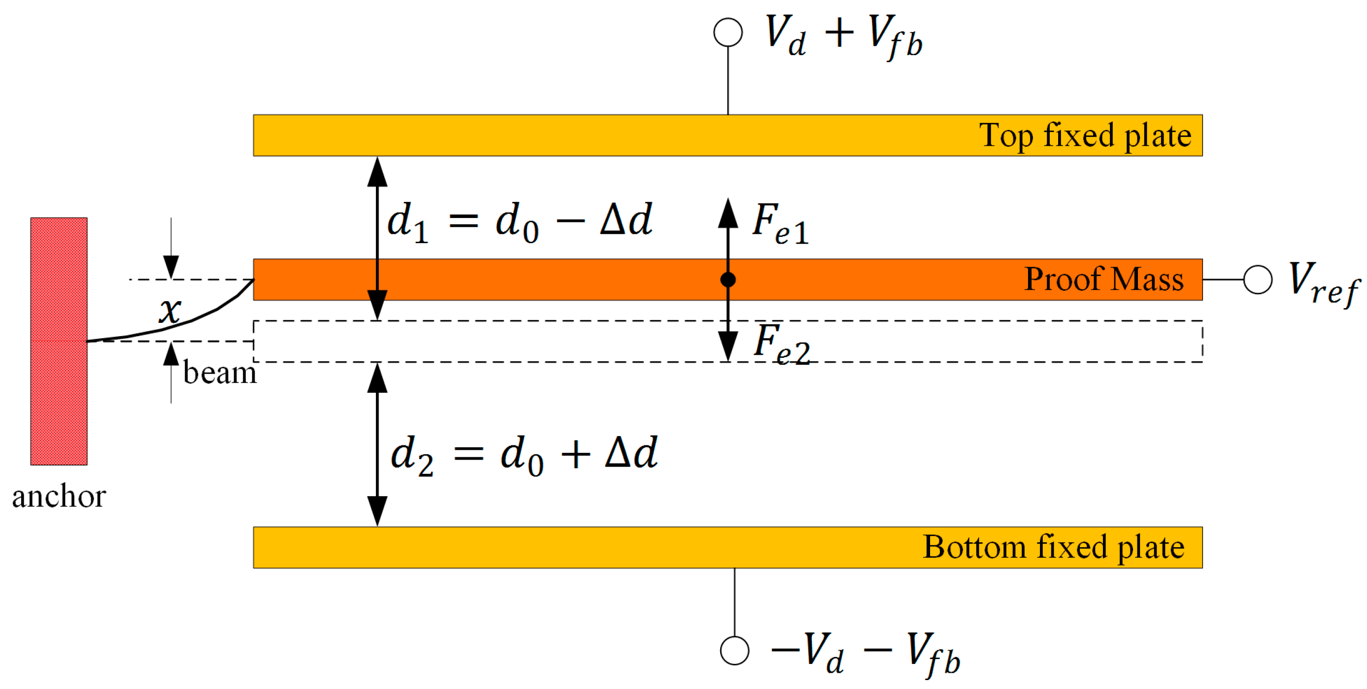
Figure 3.
Relationship between and .

Figure 4.
Measuring the equivalent mismatch between fixed plate and GND: (a) the initial state; (b) state of adding a capacitance of 1 pF.
Figure 4.
Measuring the equivalent mismatch between fixed plate and GND: (a) the initial state; (b) state of adding a capacitance of 1 pF.

Figure 5.
Mismatch of different circuit design: (a) result of before-optimization circuit; (b) result of after-optimization circuit.
Figure 5.
Mismatch of different circuit design: (a) result of before-optimization circuit; (b) result of after-optimization circuit.


Table 1.
The measuring data with different .
| 1.00 | 5058 | 137,837 | 1.00 | 7.33 × 10⁻⁸ |
| 2.00 | 1526 | 68,051 | 4.00 | 1.96 × 10⁻⁸ |
| 3.00 | −49 | 45,092 | 9.00 | −8.48 × 10⁻⁸ |
| 4.00 | −1079 | 33,768 | 16.00 | −2.29 × 10⁻⁷ |
| 5.00 | −1946 | 26,993 | 25.00 | −4.09 × 10⁻⁷ |
| 6.00 | −2651 | 22,491 | 36.00 | −6.22 × 10⁻⁷ |
| 7.00 | −3329 | 19,253 | 49.00 | −8.73 × 10⁻⁷ |
| 8.00 | −4043 | 16,811 | 64.00 | −1.18 × 10⁻⁶ |
| 9.00 | −4682 | 14,942 | 81.00 | −1.51 × 10⁻⁶ |
Table 2.
Mismatch of different sensors on same board.
| Sensor | X2 (m) | Mismatch/fF |
|---|---|---|
| 1 | −1.12 × 10⁻⁸ | −57.64 |
| 2 | −0.99 × 10⁻⁸ | −50.95 |
| 3 | −0.98 × 10⁻⁸ | −50.43 |
| 4 | −1.14 × 10⁻⁸ | −58.67 |
| 5 | −1.17 × 10⁻⁸ | −60.21 |
| 6 | −1.18 × 10⁻⁸ | −60.73 |
| average | −1.10 × 10⁻⁸ | −56.44 |
© 2018 by the authors. Licensee MDPI, Basel, Switzerland. This article is an open access article distributed under the terms and conditions of the Creative Commons Attribution (CC BY) license (http://creativecommons.org/licenses/by/4.0/).
Share and Cite
MDPI and ACS Style
Dong, X.; Yang, S.; Zhu, J.; En, Y.; Huang, Q. Method of Measuring the Mismatch of Parasitic Capacitance in MEMS Accelerometer Based on Regulating Electrostatic Stiffness. Micromachines 2018, 9, 128. https://doi.org/10.3390/mi9030128
AMA Style
Dong X, Yang S, Zhu J, En Y, Huang Q. Method of Measuring the Mismatch of Parasitic Capacitance in MEMS Accelerometer Based on Regulating Electrostatic Stiffness. Micromachines. 2018; 9(3):128. https://doi.org/10.3390/mi9030128
Chicago/Turabian StyleDong, Xianshan, Shaohua Yang, Junhua Zhu, Yunfei En, and Qinwen Huang. 2018. "Method of Measuring the Mismatch of Parasitic Capacitance in MEMS Accelerometer Based on Regulating Electrostatic Stiffness" Micromachines 9, no. 3: 128. https://doi.org/10.3390/mi9030128
Note that from the first issue of 2016, this journal uses article numbers instead of page numbers. See further details here.