Failure Detection of Composites with Control System Corrective Response in Drone System Applications †


Faculty of Computing, Engineering & Sciences, University of South Wales, Pontypridd CF37 1DL, UK
*
Author to whom correspondence should be addressed.
†
The paper is an extended version of our paper published in 1st International Symposium on Computer Science and Intelligent Control (ISCSIC 2017).
Computers 2018, 7(2), 23; https://doi.org/10.3390/computers7020023
Submission received: 4 March 2018
/
Revised: 5 April 2018
/
Accepted: 6 April 2018
/
Published: 9 April 2018
(This article belongs to the Special Issue Selected Papers from the 1st International Symposium on Computer Science and Intelligent Control (ISCSIC 2017))
Abstract
:The paper describes a novel method for the detection of damage in carbon composites as used in drone frames. When damage is detected a further novel corrective response is initiated in the quadcopter flight controller to switch from a four-arm control system to a three-arm control system. This is made possible as a symmetrical frame is utilized, which allows for a balanced weight distribution between both the undamaged quadcopter and the fallback tri-copter layout. The resulting work allows for continued flight where this was not previously possible. Further developing work includes improved flight stability with the aid of an underslung load model. This is beneficial to the quadcopter as a damaged arm attached to the main body by the motor wires behaves as an underslung load. The underslung load works are also transferable in a dual master and slave drone system where the master drone transports a smaller slave drone by a tether, which acts as an underslung load.
1. Introduction
The interest in advances in materials and the development of health monitoring solutions has nowadays gained considerable attention from several researchers (see, for e.g., [1,2]). However, it is important to note that, despite the advances in materials, there are little health monitoring solutions available when in use [1]. Super materials such as carbon fibers are becoming increasingly popular due to their inclusion in composite materials, and the continued gradual reduction in carbon production costs over recent years has allowed its widespread use, which is now commonplace in drone frames.
Failure detection methods of composite material systems are currently the subject of much research effort in the composite material community at large; see, for example, [2,3], using a variety of failure detection methods and control algorithms. For enhanced reliability, early failure detection methods with critical failure prevention are preferable as they offer a structured approach to resolve failure related issues giving essential early indication of damage and therefore offers options for preventative measures. Such an approach gives an alternative direction when compared to offline non-destructive failure detection methods. In this paper, details of a live early failure detection technique are discussed with reference to quadcopter applications (or more broadly drone systems).
With regards to the failure method and drone application, it is shown how the failure detection technique can be utilised in a drone system to enhance flight success that would otherwise not be feasible. It is also viable to add an increased level of safety by detecting physical damage to the flight controller by implementing the failure technique to the printed circuit board and related components. Operational similarities exist between a master drone and slave drone carried as an underslung load, with that of a single quadcopter and damaged rotor arm that remains attached by the electronic speed controller (ESC) wires. The single drone rotor arm in effect becomes an underslung load; therefore, both are covered in the paper as future work will progress to a dual drone system based on a master and slave. Ultimately, both master and slave drones will incorporate the control system corrective response methods providing an extremely robust and yet minimal complete system.
2. Failure Detection
The failure detection research that is of use in the drone system includes two methods; they offer differing options for the detection of damage. The mesh structure method allows an instant detection method for fractures and complete breaks in the carbon fiber composite; the wafer structure method offers detection for penetrative damage between composite plies, both of which are novel solutions to an existing problem.
2.1. Control Structure
Prior to the testing of the design solutions, a fixed control structure (control subject) was produced of carbon fibre composite. The structures contain the identical orientation of a 4-ply layer make up comprised of 430 g 2/2 twill vari preg with dimensional width and length of 30 × 300 mm, respectively. Samples are cured in a preheated environmental chamber at a temperature of 100 °C for a duration of 90 min, which conforms to the data sheet specification. Control structure samples were hand built in quantities of 10, and the test data collected gives a reference benchmark or base line for which the designs with failure analysis methods are compared against. Having a control structure and reference data such as flexural strength values, weight, conductivity, etc. allows easy identification of any structural differences the failure detection implementation may have as opposed to the bench mark.
2.2. Wafer Structure
The wafer structure method utilises ply layers as routinely found in composite materials but varies each adjacent ply with conductive and non-conductive plies. Tests were conducted with plies of carbon fibre and Absorbent Glass Mat (AGM). The first ply being conductive carbon fibre, the second ply is the electrically insulating fibre glass and the third ply carbon fibre and so forth. The technique is that, when a foreign object breaches the hybrid composite, the damaged fibrous carbon breaks through or entangles with the glass fibres and penetrates until it is in direct contact with the otherwise electrically isolated lower layer of conductive ply. This penetrative type of damage is monitored and detected by evaluating the electrical resistance between the previously isolated plies (layers 1 and 3). This hybrid composite approach benefits by having a suitable method of detecting penetrative damage, although has a shortcoming of lower strength due to the inclusion of the glass fibre when compared to a composite of pure carbon fibre as the reinforcement material. However, this can be negated when other properties are considered advantageous such as enhanced fire resistance, where Kevlar can be used as the insulating material. Material matching is required as well as suitable structural testing to ensure that the composite in its entirety provides suitable characteristics to the application. Such an example can be beneficial in the battery compartment of the drone system as the primary source of power is either combustible fuels such as oil derivatives in larger unmanned aerial vehicles (UAV), although these are typically used in defence applications, or lithium cells in smaller commercial and hobbyist type applications. A hybrid composite material layered in this fashion benefits with live detection to damage and extended fire resistance whilst providing a lightweight structure with appropriate strength. If structural strength cannot be sacrificed, then an additional ply of conductive and nonconductive reinforcement material can be added at the expense of additional cost and weight, therefore not altering the original design structurally.
2.3. Mesh Structure
The mesh method as the name implies utilises a conductive mesh structure embedded within the carbon composite at production or alternatively applied as an outer layer to the finishing carbon and covers structural areas of interest that require damage detection. This method is most applicable to the drone system detailed in this paper. If carbon fibre or any electrically conductive reinforcement or matrix material is used in the composite, the mesh wire should be of the enamelled type to provide adequate isolation between the composite. During the application to the structure, it is convenient to have both wire ends in close proximity of each other for ease of attaching the monitoring electronics. The operational principle is that a small electrical current is passed through the wire, which allows for detection of continuity with electronic circuitry. If the wire becomes severed, as would be the case from damage to the frame structure, then the mesh circuit will become open circuit and is easily detected. Using such an approach, various options become available, the drone can be autonomously landed, movements can be restricted that may contribute to further damage by altering the flight envelope, or simply alert the user, etc. Costs to implement the method are difficult to predict as the materials required for the method are minimal but come with a reasonable amount of labour to apply. This labour effort is considered on par with hand built carbon fiber products and would equate to the addition of an extra ply layer but could vary due to the complexity of the structure and would be considered on a case-by-case basis. The enamelled mesh wire used in this research paper is priced at £5.52 for 215 m at a diameter of 0.22 mm, which is an extremely low cost considering the surface area that it would cover.
3. Incorporated Electronic Design
This section describes how the failure detection method is implemented electronically and how it can be applied to glass fibre and epoxy resin compound (FR4) printed circuit boards (PCBs) as part of the normal design activities. Further information is discussed relevant to implementations of the designs.
3.1. Printed Circuit Board Design
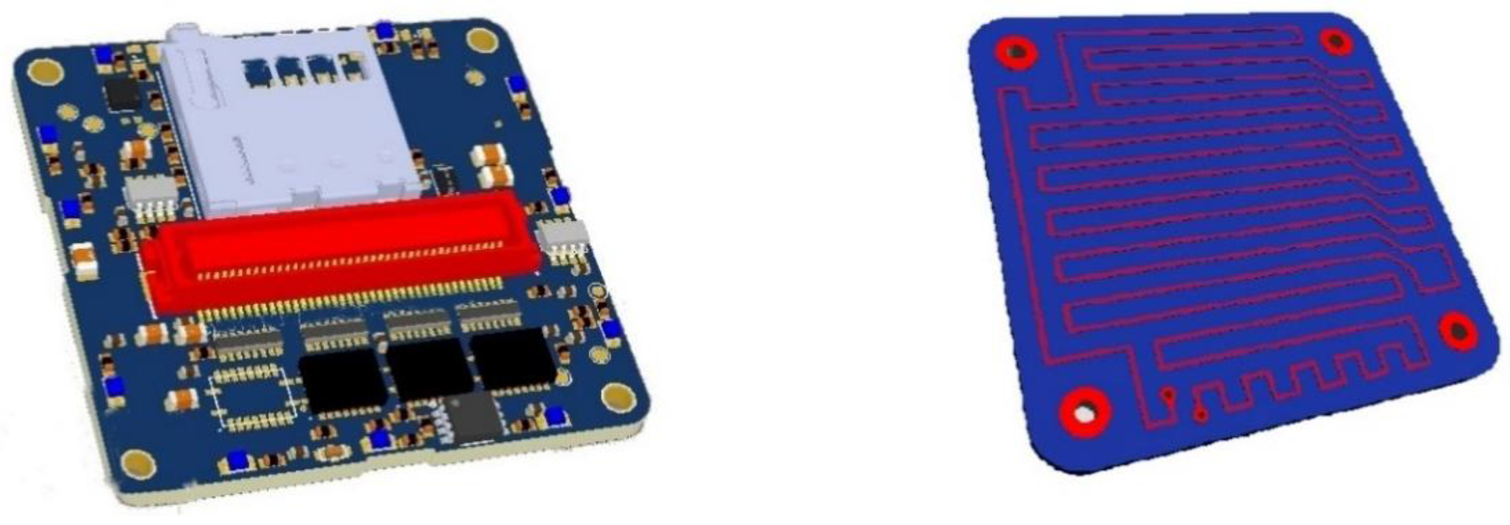
Modern consumer electronics use FR4 as its printed circuit board material, and this is also used for the drone flight controller, electric speed controller, camera electronics and, more than likely, all onboard electronics. Higher end electronics found in the Ministry of Defence (MoD) may use higher end materials such as ceramics due to their enhanced electrical isolation properties. However, the same principle applies and would work on all types of PCBs. Therefore, the physical damage detection can also be implemented into the electronics by routing tracks into the FR4 boards, and this can be seen in the flight controller PCB lower layer in the right-hand image of Figure 1.
Similarly, the same method can be applied to common drone structures and associated parts used in the construction of the frames. This is detailed in the following section but covers the same principle as that of the flight controller above.
3.2. PCB (FR4) Design for Quadcopter Applications
It is realistic to implement the damage detection method mentioned in the printed circuit board design in the drone frame when constructed of FR4 material, and this offers increased inflight safety, and this is an ideal example in which to demonstrate the failure methods simplicity and versatility. Typically, hobbyist and smaller sized drones are constructed of carbon fibre or plastic. To reduce weight, it is common to see channelled slots in the rotor arms and body, which decreases the material volume and reduces weight at the expense of structural strength, and this is especially true of highly agile race drones. It is especially common for fast and nimble race drones to have inflight collisions where critical failure does not happen instantly but damage does occur, to which the operator is unaware. As the drone is still flight worthy, it is assumed that continual use of the drone is acceptable; therefore, the drone does not make a return journey for damage inspection. It is also likely that the return flight home places further stress on the structure and it fails suddenly and unexpectedly causing the drone to fall at speed and height, causing further damage to potentially expensive on-board components. To provide a level of safekeeping that is otherwise absent in the drones structure, a simple technique can be implemented. Figure 2 below shows the drone frame typically used in hobby applications, which is positioned at the lower end of the price range.
With reference to Figure 2, the left image is divided into two sections upper and lower for ease of understanding. The upper section shows a conventional drone frame without damage detection and the lower section shows an implementation of the mesh structure method applied to the FR4 board as circuit tracks to provide the damage detection technique. A single continuous wire is placed around the lower section and terminated with PCB solder pads at the rear of the main body. The PCB pads are solder connections for the damage detection electronics. A microcontroller with a port pin drives a small current through the track returning to a high input impedance port pin that measures the voltage received back and determines damage. The microcontroller then interfaces to the flight controller, which determines the flight mode i.e., normal operation, minor damage or complete damage. The state of health can also be transmitted back to the user. To elaborate further, the flight controllers’ control strategy can be optimised to the frames’ state of health and therefore the performance envelope of the on board flight controller such as bank angles, maximum thrust or ramp angles, maximum motor speeds and even permissible G force limits can be adjusted accordingly. This reduces harsh dynamic forces applied to the drone arms and gives options for a limp home mode to ensure increased likelihood for the retrieval of the drone and on-board components. However, due to the extreme simplicity of this implementation, it lacks the capability to determine which arm has sustained damage i.e., rear left or rear right, in a similar way as a blown Christmas bulb in a string of lights does not reveal where the damage is located.
The computer aided design (CAD) image of Figure 2, on the right offers an implementation of the mesh system at an enhanced level of failure detection. The method applied to the right frame provides details as to which quadrant the damage is sustained i.e., front left arm, front right arm, rear left arm or rear right arm. To implement locational damage information, additional wiring is required that is negligible when considered with FR4 frames as this includes extra PCB track routing and does not affect cost or effort. It should be realised that a slightly more capable microcontroller is required with a higher pin count from 6 to 8. Due to the simplicity of the required microcontroller, this adds very little in terms of quad frame complexity and cost. The extremely low power consumption can also be considered negligible as the hardware can run for many years on a typical button cell battery. The task can also be achieved in discrete electronics such as a comparator; data sheet values available give a power consumption level at 60 μA for a National Instruments LP339 device (Austin, TX, USA). Extremely low power microprocessors are available today with sleep currents as low as 9 nA that are capable of the task. For example, low power microprocessors are readily available in single quantities with a pin count of 20 giving 18 Input/Output ports, 32 MHz clock frequency, and 7 KB of program memory, and interface communications include I2C/SPI/USART for the price of £0.69. Due to the low complexity to implement the method, it is possible to achieve this with any unused ports on the flight controller.
The advantages of damage detection location allow superior flight controller control strategy implementations. Knowing which arm is damaged enables the flight controller to alter its control strategy to precisely match the sustained damage. This can be to throttle back power on the damaged motor arm only and increasing surviving motor arms to compensate. In the case of severe damage on a single arm that results in complete loss, the quadcopter can auto switch to a tricopter control method with an under slung load. The underslung load being the damaged motor hanging underneath the now tricopter frame from the ESC wires ESC. For this method to be effective, an xFrame quadcopter is required. To further increase accuracy of the damage detection, tests have been conducted where the routed tracks vary in length to give a known damage detection location on both x- and y-axis and requires an additional PCB layer for track routing. This significantly increases the required number of tracks to implement but is an option should it be required. In the circumstances where UAV’s have critical missions the low cost of an extra layer of PC B this can be considered as little consequence. The resulting increased complexity can be reduced from the microcontroller point of view by the inclusion of multiplexors and coding techniques, and this is deemed to be the limit of the mesh method for damage detection.
The xFrame has an almost even weight distribution especially when considering the motor lift from each arm. The structural strength of the frame is highest at its centre due to the concentration of carbon fibre and associated side wall support in which the lithium battery and electronics are housed. It is not difficult to imagine the impossibility of continuing a flight path should one of the arms fail when operating as a quadcopter with three motors and associated propellers. Modifying the control strategy of the flight controller allows for a substitute control strategy method in which to fly the damaged xFrame, which now more accurately represents a T formation. The closest approximation is a tri rotor also known as a tri copter. Typically, tri copters have shorter front arms or booms when compared with the tail arm giving more agile roll ability, and a shorter tail arm gives more agility in pitch. The setup of each control parameter must be tuned to give suitable and stable flight as is the case with any drone. Should the broken arm still be attached by the associated ESC, the motor behaves as an underslung load to what is in essence an equal wing tricopter. Knowing the mathematical model for an underslung load, it is possible to alter the flight controller further to account for the loads momentum during flight. The total result is a damaged drone with greatly enhanced prospects to complete its mission or return to the base.
This dynamic switch of control system can be activated at the very instance damage is reported via one of the feedback channels, i.e., the mesh structure. As expected, real-life test results show that small alterations in a proportional-integral-derivative (PID) controller values can have a devastating effect to the stability of conventional quadcopters, similarly physical changes in drone loading such as battery slide can make for an unstable flying structure due to the essential matching of the PID controller to the physical vessel. Observations from tests include oscillations and judder, where the control system fights to maintain a stable and level hover that rapidly causes thermal runaway in the motors and, ultimately, failure by motor winding burn out. By implementing the mesh structure and having the quadcopter optimised for each failure eventuality, it is achievable to have a stored fall-back control system that best relates to the damaged vessel. It is worth noting that higher end flight controllers (usually non-race) have an impressive array of instruments and sensors such as global positioning system (GPS), magnetometer, gyros, etc. that can aid or potentially reduce the complexity of the mesh structure.
4. Experimental Study
So far, the details of failure detection techniques together with an overview of the technique implemented in a PCB design is presented. Now, the difficulties associated with underslung loads shall be presented with the specifications of the master slave drone system works in progress. Also presented in this section is the aim and scope of the project for which the research is motivated towards, providing a comprehensive understand of its focus.
Drones System
Drones are deployed in the areas of search and rescue, military and scientific studies. In search and rescue operations, rapid rescue operations are essential for preservation of life, and, in harsh environments, a (dual) drone system operation is considered desirable. In this study, a master and slave drone system configuration is considered. The master drone is attached to the slave drone by means of a tether that can be detached and reattached automatically through the drone controller system, and this is shown in Figure 3.
Considering the control of a dual drone system, the dynamical model of the system has terms that are uncertain. Uncertainties may arise from the master to carry the slave or the immeasurable parameters in the dynamical model. Additional uncertainties may also arise from computational errors of the dynamic effects resulting from aerodynamics. Therefore, for a realistic model of the system, potential uncertainties must be taken into account during the flight controller design. A mathematical model of a dual drone system presented in [4] is adopted in this work. The interest in designing a controller for a drone system has gained considerable attention in the last few decades [5,6,7]. Choosing the control technique depends on the control target the vehicle must meet [8]. There are many important possible flight missions, such as stabilization in hover conditions, straight line trajectory, complex maneuver, collision avoidance, pickup, loading and releasing object, and take-off and landing need to be controlled properly, since the system is an uncertain dynamical system.
From the review of popular drone system control methods, it is clear that considerable attention has been paid to the design of a controller to obtain a satisfactory result. The control problem has been tackled using different approaches ranging from linear quadratic control [9], sliding mode control [10], adaptive control [11], feedback linearization [12], tracking control [13], and back stepping based PID control [14]. Apart from the methods emphasized above, many other techniques are reported for complex modern control system design. In general, there are two main approaches for control of uncertain dynamical systems, that is, deterministic and stochastic control. If the uncertainty in the system model is assumed to have statistical characterization and the desired behavior of the system is described in a statistical sense, a stochastic approach is feasible; otherwise, if structural properties and bounding conditions relating to the uncertainties are known, a deterministic approach is appropriate. Deterministic feedback control of uncertain dynamical systems proposes the use of determined linear or nonlinear feedback control functions, which operate effectively over a specified magnitude range of system parameter variations and disturbances, without any online identification of the system parameters. The benefit of such an approach is that no statistical information of the system variations is required to yield the desired dynamic behavior and, hence, the controller may have a simple structure for implementation in practical systems. However, the deterministic control design methodology requires that the system state vector is available for measurements, and the bounding knowledge of uncertainties are known, which may put restrictions on the applications of this method.
Considering the mathematical model presented in [4], the combined system model will have a structure of a cascade connection of the two subsystems; therefore, the system will have the following format:
where , .
In general, mathematical models of dynamical systems are usually imprecise due to modeling errors and exogenous disturbances. Equation (1) can be considered as the nominal part of the system model and the uncertainty can be modeled by as an additive perturbation to the nominal system model, more specifically, the structure of the system has the form:
where models the uncertainty in the system. Thus, using the kind of nonlinear system structure described in Equation (2), a nonlinear deterministic controller can be designed for the dual drone system. The key advantage of this control method is that the controller design takes the system uncertainty into account. The controller can give a guaranteed stability region for the systems considered. This method should have the potential for solving some problems arising in dual drone system control and underslung loads. For a complete understanding of the underslung load strategy, Refs. [15,16] should be viewed in their entirety, and it is deemed unnecessary to repeat the works of this paper here.
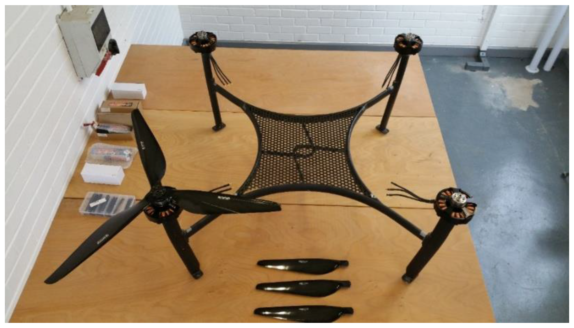
The development of a control system for the dual drone system requires the development of an adequate test-bed setup for the experimental study. Recently, many set-ups have been designed and built to provide required condition for conducting experimental tests on quadrotor and for evaluating the performance of the vehicle. Set-ups and experiments can be divided into three categories: aerodynamics, attitude and altitude control, and six-degrees of freedom motion control. A set-up is built to provide six degrees of freedom motion for the dual drone system. It allows the master (quadrotor) to rotate on its yaw, pitch, and roll axes and move vertically, while, for the slave, pitch and roll movement can be measured. The prototype system currently utilizes the master drone with a weight of 10 kg, and the body dimensions are comprised of a height of 50 cm and a width and depth of 100 cm. The wingspan or propeller-to-propeller dimension (tip to tip) is 176.2 cm. The available thrust totals 62 kg across all four rotors giving a capable payload of 20 kg. The remaining available thrust of 32 kg is reserved for flight and stability during hover functions, and the total cost of the basic build is approximately £4000. The slave drone current weight is 1 kg and is spherical with an outer radius of 15 cm. The shape of the slave drone allows for damage resistance and docking options that are not possible with conventional drone structures. It is capable of 6.8 kg of thrust giving a capable payload of 2.4 kg, which allows optional equipment to be carried for the use in search and rescue, military or scientific applications. Typically, this could include high zoom cameras, infrared camera, additional power packs for extended flight time, and measurement equipment such as sensors and more. The basic cost of the prototype slave drone is £600 with no additional equipment mentioned (Figure 3). The Master drone can be used to carry the slave into environments where it would be unrealistic for the slave to approach unassisted, such as over large flight times or hostile conditions such as high winds. The slave can then undock and perform functions that would be unfeasible for the master. These can include tight spaces or scenarios where the potential loss of the master would be too costly to perform such a risky mission.
Flight data from the slave can be relayed back to the master, reducing the communications distance to the user and reducing the power requirements of the slave communications. Lower cost drones of less than £50 is achievable and considered disposable for the current research purposes. This is promising for data collection with greatly reduced costs, thus allowing data to be collected in environments where it may have been not viable, such as volcanoes, war zones, tornados and the like. At its simplest, a dual drone system allows for increased flexibility during missions. The master drone primary function is to transport slave drones to the mission site and store or relay the slave drone data collection as well as relay user flight control such as roll, pitch, yaw and thrust to the slave, utilizing the increased sensitivity of the larger more powerful antenna capability of the master drone. Progressing the research, further multiple slaves will be docked to the master. Slave drones can be custom built for the environment and loaded to the master at short notice, allowing for rapid deployment of drone swarms that are customized to the mission. For example, should a situation arise where a chemical hazard is suspected, it will be possible to load the master drone with a slave drone capable of detecting such a chemical that can be sent into the hazardous area. This allows the master drone to fulfill its function of flying greater distances than the slave would be capable of, thus maintaining the safety of the operating crew and yet massively reducing financial loss should the drone fail to return to the master drone. Data can be stored or relayed through the master that would allow for a greatly improved success rate of returning the critical data back to the mission crew. Similarly, slave drones with cameras could undock and monitor the mission from a different perspective if only a single master drone was utilized that is typical of the current technology. Future research is focused on autonomous drone swarms that rapidly relay captured photos of areas in close proximity useful in military applications where gunfire may be present. The financial loss of a slave drone can be considered negligible in comparison to the value of the data collected. Typically, in such situations, a larger and extremely expensive master drone takes aerial images with high zoom cameras. Arguably, low cost camera photographs at ground level would provide more valuable data in such situations. These autonomous rapid moving drone swarms, due to their minimal physical size and reduced weight, would be extremely difficult to disable, allowing for greater success rates. Such slave drone flight times currently stand at 20-min flight times but are capable of reaching speeds nearing 100 mph. Flight patterns of such drones would be similar to that of a dragonfly, where they would fly at high speeds to a hover, capture imagery and move on.
5. Development
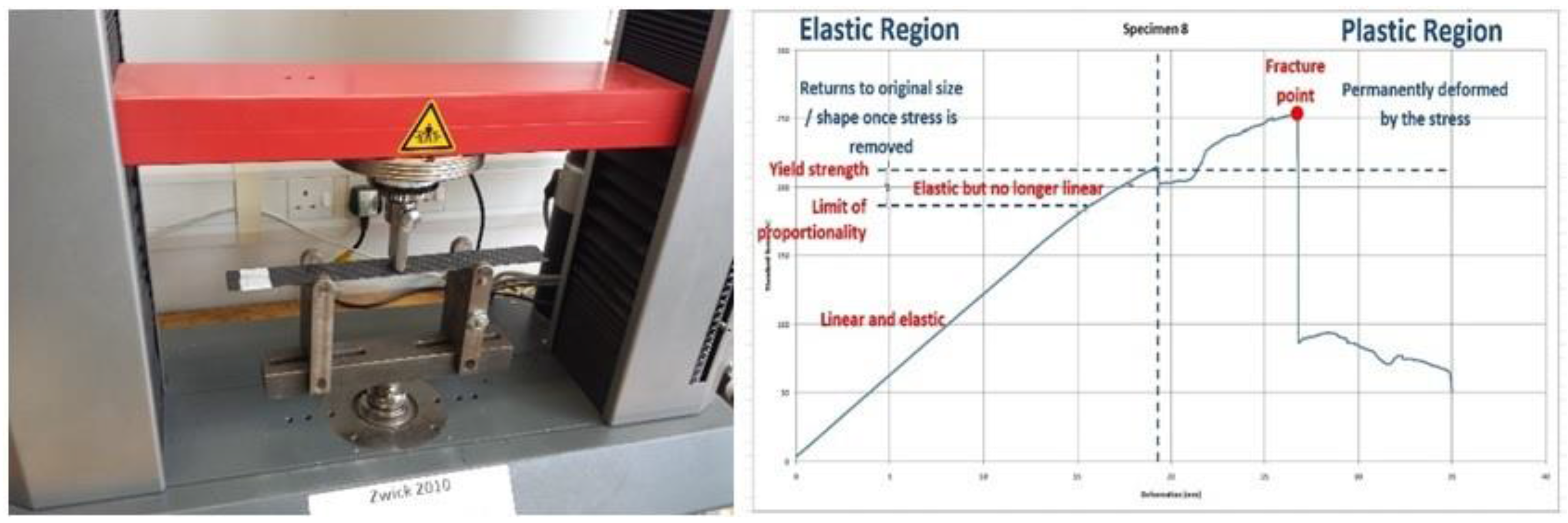
Currently, tests have been conducted on multiple carbon fibre samples with a 4-ply stack of 30 × 300 mm dimension with promising results for the mesh structure consistent with the implementation in the drone application in the paper. With reference to Figure 4, a specimen test setup on a Zwick Z010 machine (Ulm, Germany) (left) can be seen for a 3-point flexural test with the corresponding data (right), and regions of interest have been added to the graph to aid analysis.
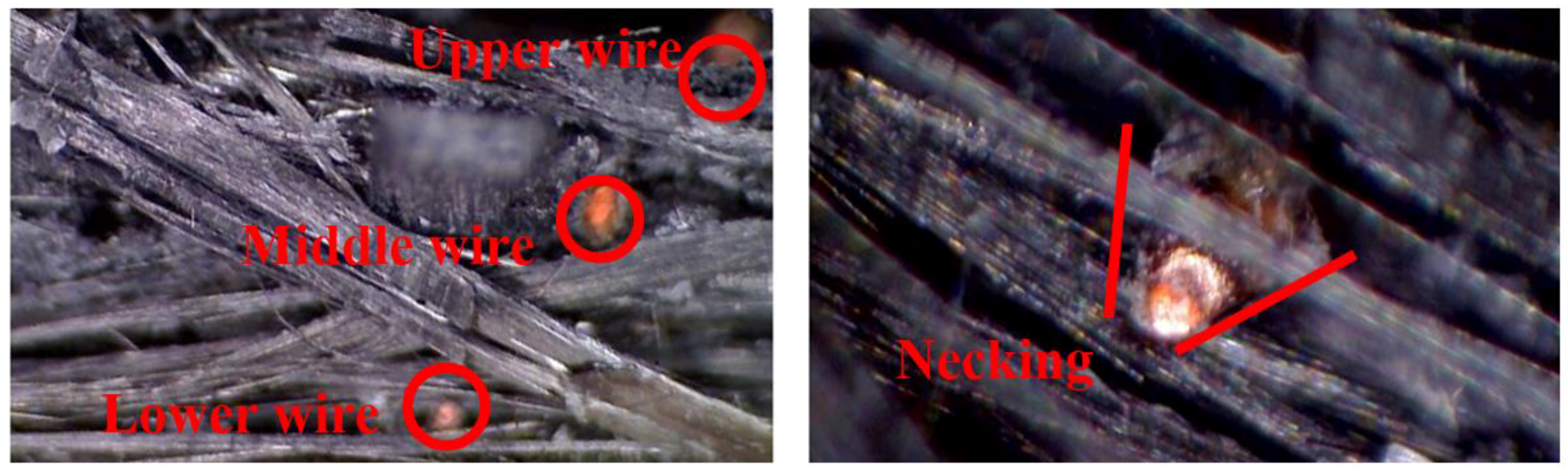
From the batch samples tested, there was approximately a 50% success rate at detecting damage when the sample transitioned between the elastic region to the plastic region. As can be shown in the above chart, considerable damage occurs in this area, although there may be no observable signs of degradation. Results for this batch sample include the mesh system embedded within each ply stack of the sample, which consists of enamelled copper wire of 0.22 mm diameter. The limited detection rate at this transition stage has been concluded to be the result of inadequate coverage of the wire mesh within the plies, coupled with the mesh material being copper and its large diameter. The reason for this is that the fracture lines are not always located at the imbedded mesh location. It is also possible to not be detected due to the elastic modulus of copper. This is more easily recognised with the magnified image of a specimen sample as shown in Figure 5.
The left image shows the three mesh wires embedded between the plies, the upper wire would be ply 1 and 2 the middle wire ply 2 and 3 and the lower wire ply 3 and 4, which completes the 4-ply carbon sample makeup. It can be seen that the wire mesh almost identically aligns on the vertical plane, which allows for a large area of the carbon fiber to be absent with the detection method. The image on the right (Figure 5) shows necking in the copper wire. Due to the cured carbon epoxy composite being more rigid than the enameled copper wire, it is possible for the carbon to suffer damage before the copper wire becomes severed. The result is that copper is a less than optimal material choice, and this effect is expected to be minimized by reducing wire diameter. However, under no circumstance has the system failed to trigger a damage event when substantial damage has occurred in the sample specimens under flexural tests. Further work is required to perfect the mesh system, which will allow for increased damage detection rates before catastrophic failure. Works are focusing on detection materials that are more closely aligned with carbon fibers’ Young’s modulus and indeed carbon fiber itself is being used with various methods to insulate the carbon mesh from the structure without reducing the structural integrity of the specimen.
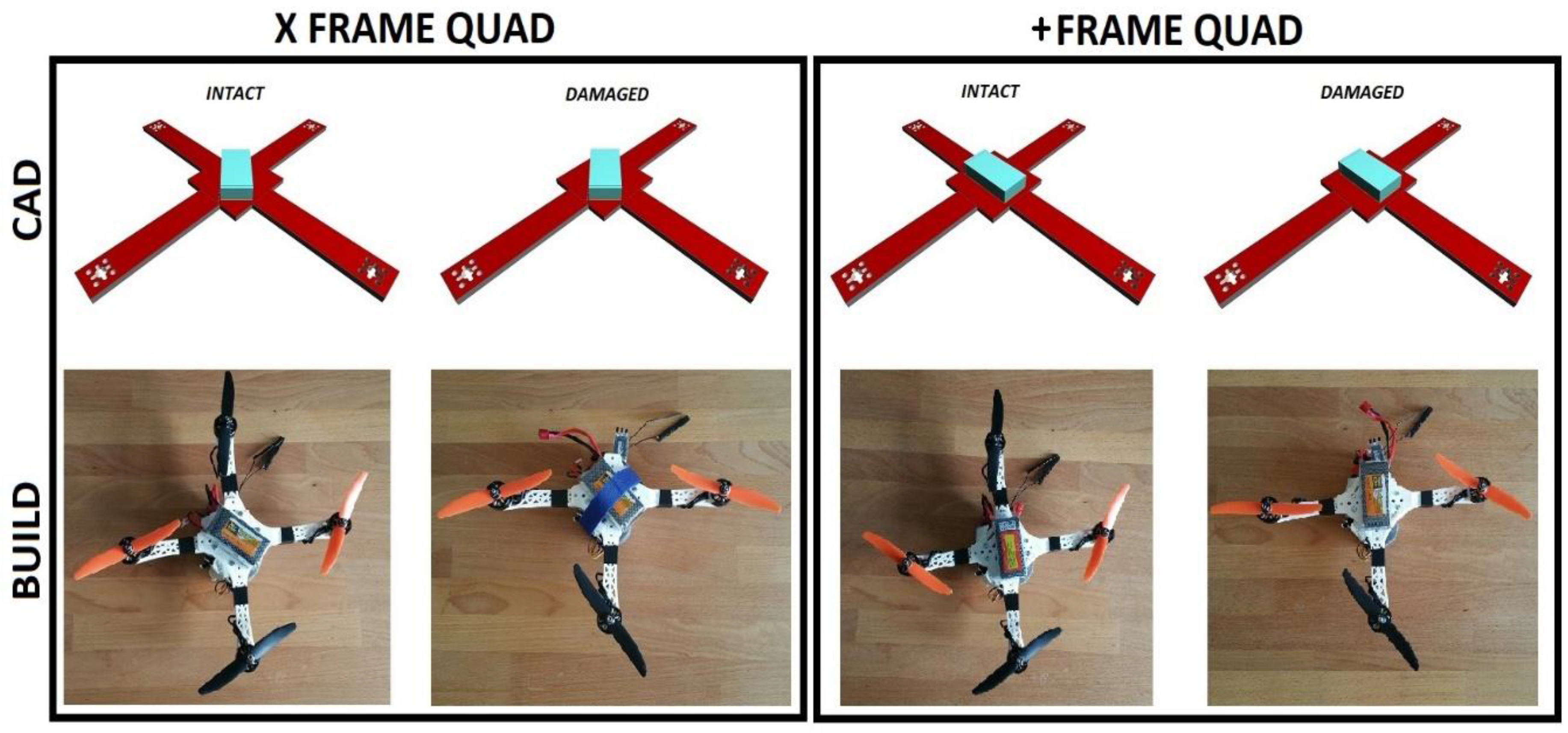
Drone testing on a hybrid-X frame structure with a missing flight arm/rotor has shown that altering the flight controller to a tricopter setup has reduced impact when in a crash scenario. The hybrid-X frame that strongly resembles the H frame where weight distribution is concerned is difficult to control and spirals downward in an uncontrolled descent at a lower velocity than would otherwise occur if the flight controller was operating as a quadcopter. It is expected that improvements in the flight controller source code would allow for controlled descent but would prove extremely difficult to allow for such a frame with a damaged rotor arm/rotor to achieve operation in that controlled flight is maintained; however, this has not been tested further due to the availability of more advantageous approaches. An altitude of 2 m was used for the drop tests and no further tests are expected on the hybrid-X due to the preferred frame setup of a true X quadcopter, which allows for a more ideal weight distribution and therefore more forgiving. Although an xFrame is mentioned, tests have also been conducted on a +Frame, as its frame is identical, and it is only the flight orientation that alters with respect to the rotor arms. This is more easily seen with reference to Figure 6. The figure shows the CAD representation at the top and the corresponding test build directly below (there is a visual offset of 45 degrees in the figure due to photography orientation). It is further divided with the left image showing the xFrame and the right image showing the +Frame, and it should be visually apparent from this that the frame is indeed identical. It is more easily recognized by observing the CAD frame the battery placement. This is considered the key component due to its weight when compared with the remaining components required for flight. The symmetry of both quads is visually apparent, the only discrepancy is the battery, and the flight controller is considered negligible as the weight of this component is 21 grams.
When looking at the CAD xFrame quad, the flight path is directly up as the page is read. If damage occurs and an arm is lost, then the forward flight path is reoriented to the direction of the lost arm. This offers the best physical setup for flight. It can be seen that the weight distribution is slightly off due to the lithium battery pack, although successful takeoff and landings are achieved with this setup. The flight controller software for the “INTACT” version and the “DAMAGED” version as labeled in the figure differs. The intact version runs on a quadcopter and the damaged version on tricopter software. It should be noted that tests between have been programmed manually and initial flights are taken from the ground level. As such, dynamic flight switch over of software from quad to tri has not been tested and is under development with a larger build frame and accompanying test rig. The flight controller must have an offset of 45 degrees in the case shown below to take into account the new forward flight path. Similarly, the +Frame quad operates on the same principle and differs only in its original forward flight path and that of the weight distribution from the lithium battery source. This setup has also been successfully tested for takeoff and landings. It should be acknowledged that takeoff and landings are completely ineffective when operating in quadcopter configurations with a missing rotor arm. Both methods can be seen to be almost operationally identical. To make the similarities more closely matched, the lithium battery will be physically square on future builds and have a symmetrical weight distribution across its central point. The test frame for experiments mentioned is seen in Figure 6. This is three-dimensional (3D) printed with Polylactic Acid (PLA) with a 100% infill and detachable arms via m3 bolts/nuts, allowing for a convenient switch between intact and damaged frame types without the need to constantly rebuild frames due to damaging the arm for each experimental test.
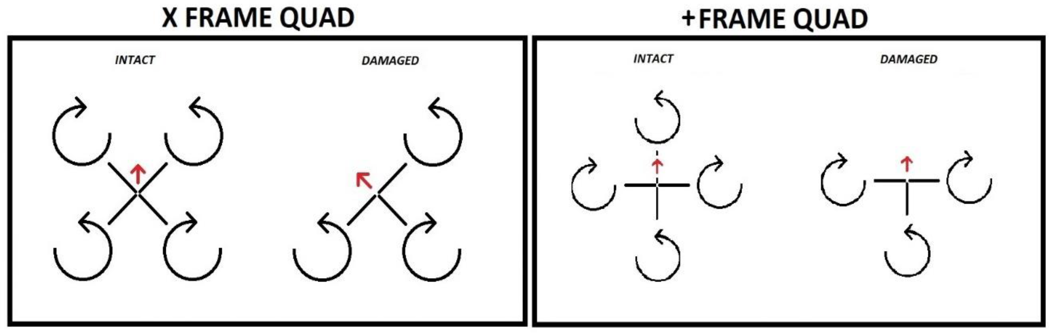
It is of significant importance to note the rotor operating direction for the proposed frame types, in a similar arrangement as Figure 6; Figure 7 shows rotor direction of both intact and damaged setups. For the flight controller used, the rotor direction of the xFrame and +Frame quad setup meets the requirement and this rotor operating direction is typical of such frames. The rotor direction is arbitrary for the tricopter and this allows a seamless switch over of flight controller programs when falling back to a tricopter operation in a damage situation regardless of which arm is damaged. This effectively gives complete symmetry when in tricopter mode. This is important as change of rotation is not possible for these builds, as the propellers produce lift in one direction only i.e., clockwise (CW) or counter clockwise (CCW). Rotor direction (i.e., CW/CCW) is shown in Figure 7, with an accompanying arrow indicating the forward flight path for each frame type. This helps understanding of the transition between intact quadcopter frame to damaged quadcopter frame. It can so far be seen that a damaged rotor arm can be detected through the failure mechanism with a tricopter software switchover and a directional offset applied to create a new flight structure. As referred to in Figure 7, the intact xFrame Quad has a lost rotor arm 1 (10 o’clock position); therefore, an offset of −45 degrees is introduced to the sensor data and the software fallbacks to tricopter control mode. As the frame is pre setup in both quad and tricopter with its corresponding software, the PID controller values are already set correctly ensuring that, once damage does occur, the most applicable version of software and tuning is pre incorporated giving continued unaltered flight. This has historically not been achieved in quadcopter designs.
Empirical evidence delivers extremely promising results for the xFrame and +Frame setups for both quad and tri frame i.e., intact and damaged. As previously mentioned, further work is ongoing to dynamically switch flight controller profiles and PID values as a result of inflight damage, from here it can be determined how successfully the damaged quadcopter transfers to a tricopter flight mode live. It is expected that the quadcopter will need a margin of ground clearance to allow for altitude loss during such a transition as the tricopter attempts to reestablish control from an uncontrolled descent back into a steady flight. If already operating at low altitude, then damage as a fall would be highly unlikely and a takeoff would be possible provided an upright position was maintained at ground level. It may also be possible with the advent of recent advancements in accelerometer methods [17] to predict a detached rotor arm or ill performing rotor due to the lack of lift in that quadrant of the drone. It therefore maybe possible to replace the mesh damage detection system and use accelerometer metrics to detect damage; however, this would require the use of high computation algorithms to which an assumption must be made. The response time would be drastically increased to that of the embedded mesh technique but could prove an alternative or enhance the system in place. No work in this area has been carried out to date but will be considered in future works and is worthy of recognition.
The flow diagram for the novel quadcopter is shown in Figure 8. This shows the functional activities required in order to implement a robust corrective flight controller response in order to maintain flight when damage has been sustained to a motor arm or boom. The flowchart relates to a PCB quadcopter frame with four lines of damage detection per rotor arm. If minor damage occurs, then the maximum number of faults can be three of the four tracks. In the event of 4-track damage on the one motor arm, then it can be taken that the arm is detached from the quadcopter main body. For purposes of explaining the flow chart, an example scenario is presented that allows explanation of each flow chart block.
The scenario is an xFrame quadcopter that is inflight and performing under normal operating conditions. During the flight, a small fracture occurs on a rotor arm, flight is continued and the fracture perpetuates further until the entire rotor arm detaches from the main body. The rotor arm and associated motor is hanging underneath the damaged quadcopter by the ESC wiring as an underslung load. Eventually, the ESC wires become disconnected by the connectors and separates from the quadcopter entirely.
Following this scenario through the flow chart, under normal operating conditions, the flow chart endlessly loops around blocks 2 and 3 poling for damage. A small fracture occurs on the rotor arm and the flow chart permanently exits the damage poling. The damage location references the track to the corresponding arm in block 4. As the damage arm count is less than 4 (determined by block 5), the restricted flight envelop is initiated, which limits G-Force, bank angles and acceleration, etc. ensuring less stress on the damaged rotor arm. The flow diagram loops between blocks 5 and 6, keeping the quadcopter in “restricted flight envelope” (block 6). Flight is continued and the fracture perpetuates further until the entire rotor arm detaches from the body. This is determined by block 5, which now progresses to block 9 and poles for motor detachment. As the arm is still connected to the motor wires, we progress to block 10 and the quadcopter now operates in a tri-copter with underslung load (the motor hanging from motor wires). Whilst in this state, an endless loop exists where the motor wires are poled for connection and the flight controller is kept in tri-copter with underslung load operation. To continue with the situation, the ESC wires become disconnected by the connectors and separate from the quadcopter entirely. Block 9 flags that the rotor arm is detached and this decision is called by block 7 to enter the final block 8, whereby the quadcopter is now a tri-copter. The flow charts ends here. It is possible to continue monitoring the remaining rotor arms and again adjust the flight controller to a restricted flight envelope, but this will be considered in future works.
Test flights have been conducted with telemetry data collected on the 3D printed +Frame operating with three arms (shown as “damaged” in Figure 6). The tests were conducted in unfavorable environmental conditions, in an exposed and open field with no shelter from the elements. Weather reports by the met office at the location and time of flights state that 4.4 mm of rainfall, northwesterly winds of 13 miles per hour (mph) with gust speeds of 22 mph, air temperature of four degrees centigrade and relative humidity of 95%. The drone setup is not tuned when relating to the PID controller and is deliberately operating with poor flight controller response. Oscillations are present in the motors as it attempts to stabilize with the ill configured PID profile. When operating under these conditions, motor coils produce excess heat that will eventually burn out and cause complete motor failure as the insulating material burns off and conducts current between the windings. Flight controller stabilization is manual only, 2D hold and GPS coordinate locking, and wind rejection is inactive. The test is intended to deliver telemetry data in the most unfavorable conditions to deem if the method is adequate for minimizing damage from uncontrolled landings resulting from inflight damage. The drone remote control is unaltered and operating as would be in a quadcopter setup (Figure 6 “intact” frame). A total of ten flights were taken with small after flight rests of several minutes to allow motor temperatures to return to normal operating conditions.
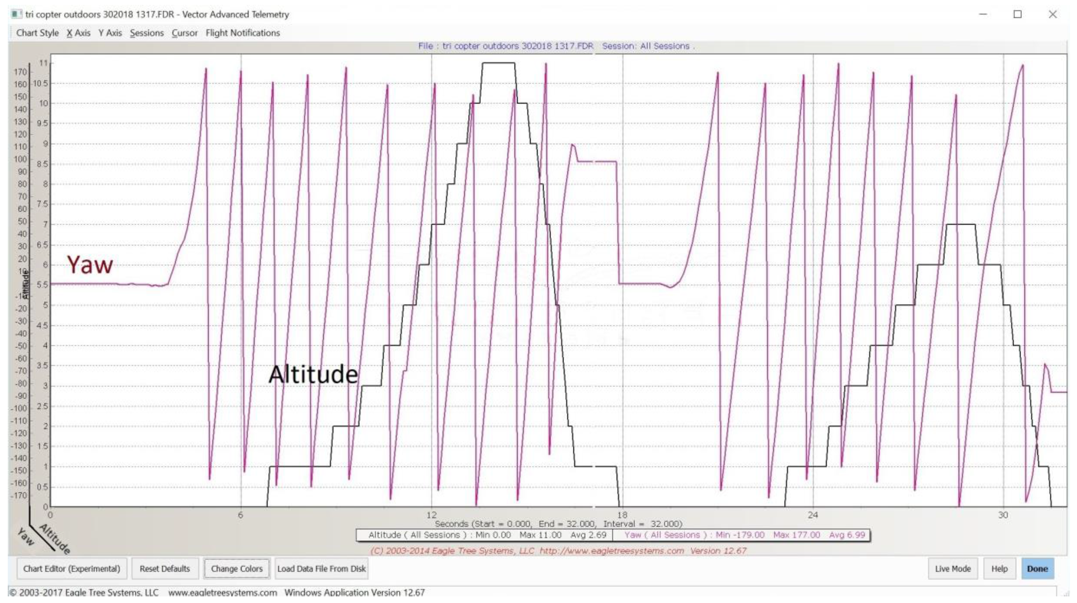
All flights were successful, and two successive flight telemetry data are examined in this paper. Due to the large amount of data present, the four graphs have been plotted independently to allow ease of viewing. All graphs show altitude in meters on the y-axis with the x-axis showing time in seconds. The graphs display separately throttle gain (Figure 9), roll (Figure 10), pitch (Figure 11) and yaw (Figure 12) to demonstrate flight dynamics and the stability of the system. Although additional data is logged, these parameters are most valuable for illustration of the system. Data for each parameter are logged at a frequency of 1 Hz in this instance.
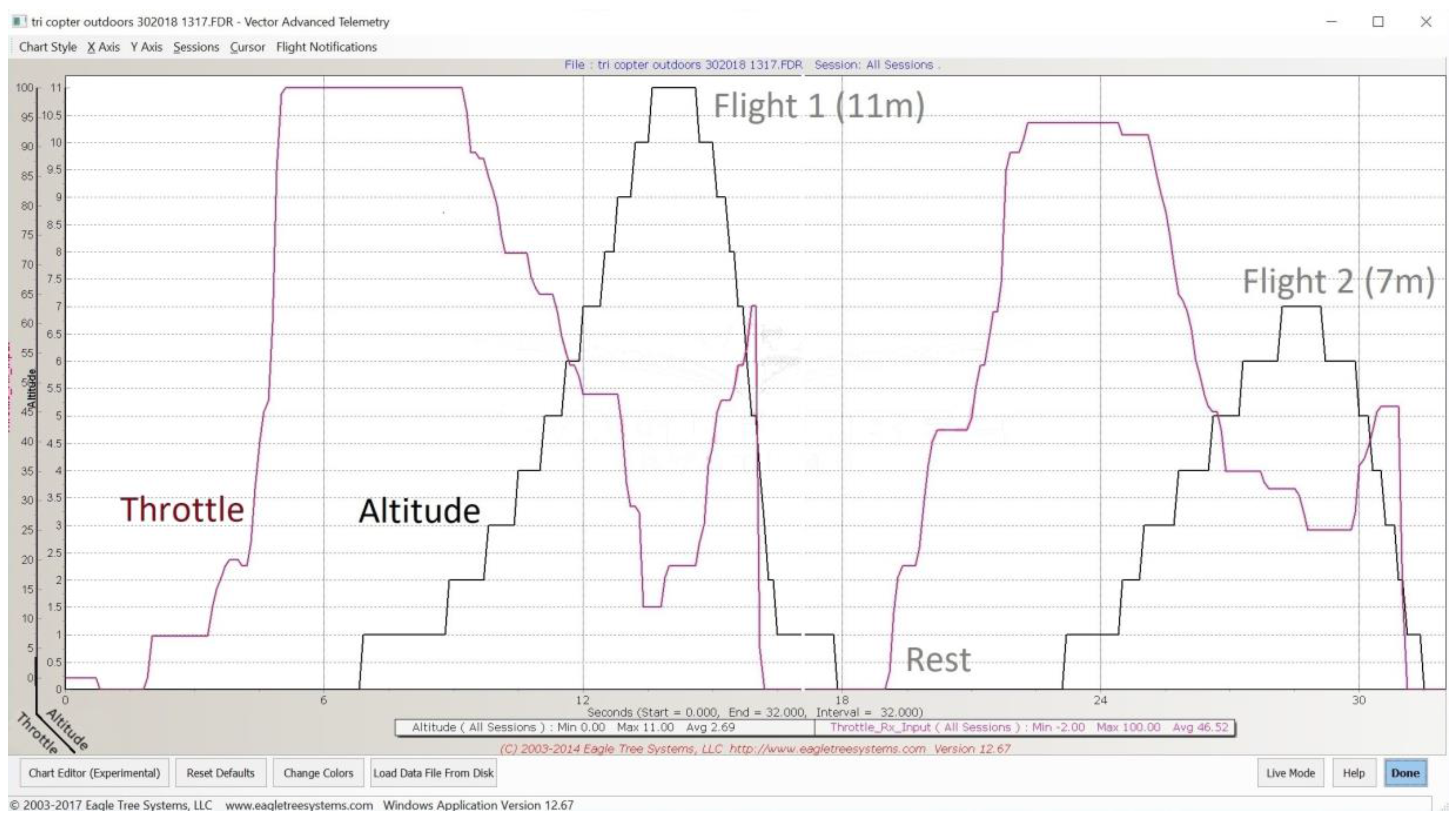
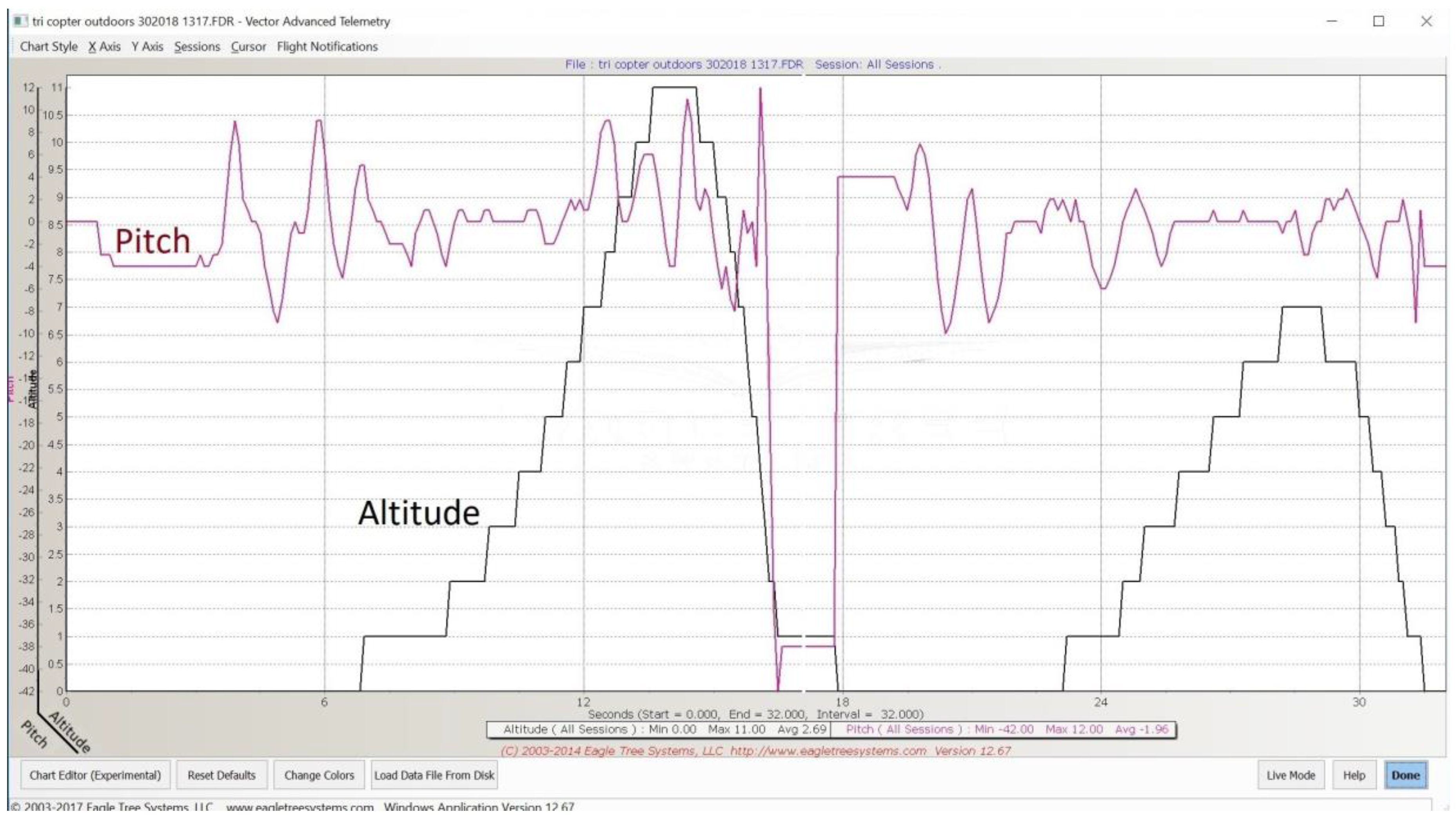
With reference to Figure 9, throttle gain can be seen with the drone altitude. It can be seen that two short flights are present. Peak altitude is marked on the graph by “Flight 1” and “Flight 2”, which achieve altitudes of 11 m and 7 m, respectively, with a small rest in between flights. Response in throttle is as expected with altitude gain, and a steady rate of climb and descent is achieved with no difficulties. Figure 10 shows the corresponding pitch data again with altitude shown as to allow easier reference points across the graphs (throttle, pitch, roll, yaw).
Responses to pitch are also stable and within the default flight envelope set to a maximum 25 degrees bank angle. Fluctuations are typical especially under the wind and rain conditions of the flights. The sharp change in pitch seen at the end of flight 1 and start of flight 2 shows where the drone was picked up at the end of the flight to toggle power, which allows logging of separate flights. Roll data is seen in Figure 11.
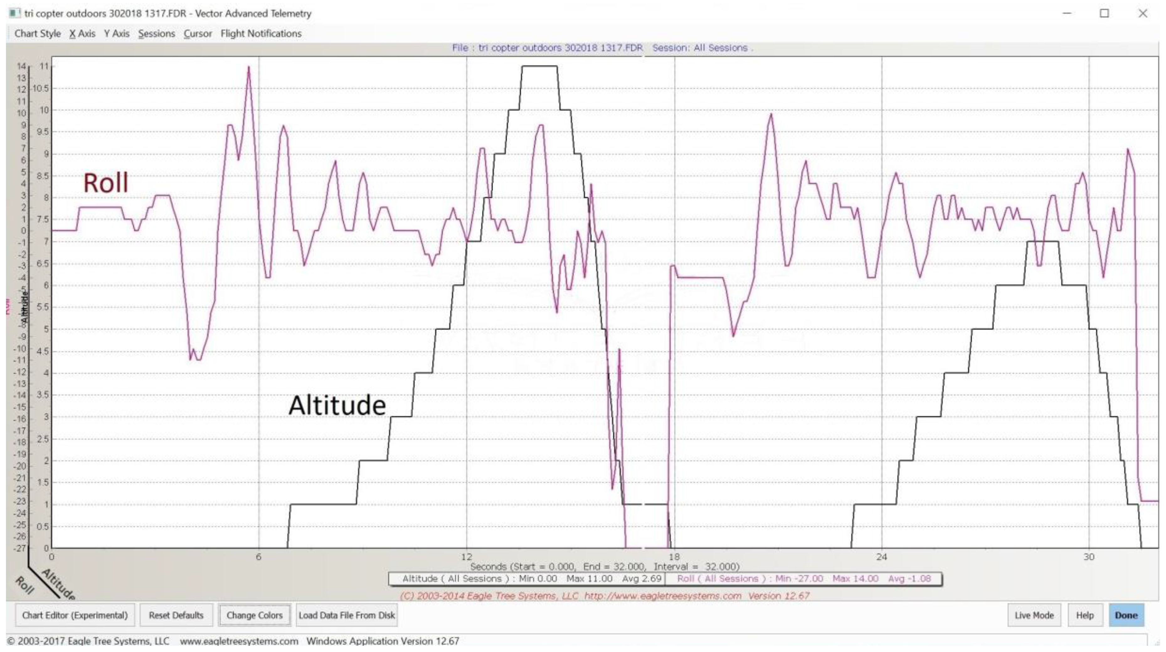
The start of the flight induces a rather significant roll factor, which could be accounted for by uneven motor spin up. This smooths out and maintains the flight envelope default settings of maximum bank angles of 25 degrees. Overall, the data shows adequate response for sustained flight especially when considering wind and gust speeds. Again, excessive roll spikes at the end of flight 1 can be attributed to the manual handling of the drone to toggle a new flight and perfectly aligns with the graph showing pitch of Figure 10. Accompanying yaw data can be shown in Figure 12.
Similarly, yaw data is also as expected, and the yaw rate is consistently steady and stable in both flights. The graph shows yaw at the start of both flights at 0 degrees, yaw continues to increase to 180 degrees and then transitions to −180 degrees, before steadily returning through 0 degrees, returning to 180 and repeating as expected. From the graph, the yaw rate can be seen to transition approximately five times in 6 s giving a rotational frequency of 0.83 Hz. If the yaw sensor data was organized so that it was incremental through positive and negative as it rotates, then the yaw graph of Figure 12 would show an almost perfect sinewave showing stability in yaw. This is expected in the tri drone due to an uneven number of motors, which therefore gives unequal torque across the drone, which is cancelled out in the quadcopter setup by having the motors counteract each other i.e., 2 clockwise and 2 counterclockwise. The rotation in these test flights is clockwise due to the loss of the rotor arm. It is therefore clear that the tri drone can also rotate counterclockwise depending on which rotor arm is damaged. However, for the purposes of the telemetry flight tests, this is considered irrelevant, as we simply want to prove that steady and sustained flight is achievable. Conventionally, tri-copters cancel this torque imbalance by utilising a servo motor that rotates the tail rotor to compensate. This approach is not dissimilar to the helicopter solution of a rear prop, although this is typically fixed for such vehicles.
Due to the restrictive size of the first stage trial drones (Figure 6), a larger drone is being constructed that more accurately represents professional UAVs. Additional equipment will be fitted such as flight telematics to display and log flight data such as motor voltages and current, altitude, speed, rpm, G-force X, G-force Y, Amp-Hours, climb rate, Airspeed and more at a rate of 40 Hz. The phase 2 drone will also serve as the master quad, which will carry the slave drone as an underslung load in the dual drone setup shown in Figure 3. The master drone progress is shown in Figure 13. When observing the graphs, it can be seen that stable flight is achieved that is within the defined control parameters of the flight controller, which would allow for continued flight. This extended flight time for the drone offers a valuable safety margin to allow the drone to come to a soft and controlled landing that conventionally would not be present.
6. Conclusions
In this paper, a novel early failure detection method for composite materials is discussed. This offers a low cost and minimal overhead approach by flexible design that allows for multiple implementations that can be tailored to the task. Tests conducted on sample specimens prove 100% successful when critical failure occurs. Pre catastrophic failure detection rates currently stand at 50% for the test specimens, although sufficient evidence is provided by the test results to allow this to be optimised further, which will result in higher detection rates. For the purpose of the drone system proposed in the paper, the method is perfectly adequate to allow the implementation of a corrective response in the flight dynamics. This failure method can also be implemented in FR4 PCBs as used throughout the drone electronics. Other than serving as a warning sign, the failure detection in PCBs would offer little advantage unless redundant components were available on the drone. However, the approach would prove extremely effective on FR4 PCB drone frames and this method is suitable for mass production as conventional routes of PCB supply can be used. Benefits of damage detection are also discussed as new opportunities become available for maintaining flight and at reducing damage on drone crash landings when compared to non-damage detection capable drones.
A dual drone configuration is explored and shares similarities with drone failure modes. Therefore, works in this area are shared across topics and offer an increasingly robust system. The dual drone system furthermore offers a reduced risk configuration when compared to a single high cost drone such as in the areas of search and rescue, scientific research and military applications. Currently, the master drone is in the prototype build stages and will allow further development of the underslung load model in the flight controller, which can also be used in the slave drone whereby a detached rotor arm hangs under the frame by ESC cables.
Drone frame structures have been built and tested to determine the ideal frame format when coupled with the mentioned damage detection and flight controller fallback mechanisms. Tests indicate that the xFrame format with symmetrical weight distribution is favourable. While low height drop tests of 2 m on the H frame format proved that damaged was minimised on ground impact, it failed to maintain flight. No further tests were conducted on the H frame due to the favourable symmetrical format of the xFrame. Tests on the xFrame proved entirely successful over ten successive full flight tests when the flight controller was implemented with tricopter configuration. Tests on this frame were deliberately conducted with ill performing PID implementations in unreasonable weather conditions to determine the flight dynamics in demanding situations. Test flights were short in duration—of less than 20 s—to prevent motor burn out, although a maximum height of 15 m was achieved. Although arguably test flight times are short, it is deemed sufficient for such flying structures as they are inherently unstable and provide no lift from the structure itself as would be the case in fixed wing vehicle flights that produce lift from air speed.
Visual observations of the drone during flights were stable and maintained controlled takeoff and landings appropriately. This relates accordingly with flight telemetry gathered during flights. The drone yaw rate was seen to be almost 1 revolution per second and this is due to the lack of counter measures to the torque produced in the rotors. This is as predicted and would prove extremely difficult to navigate to a target co-ordinate, although it provides a sufficient means of recovery from an otherwise complete failure. Tests were also conducted with no electronic assistance that is commonly found in mid-range flight controllers such as wind rejection, 2D hold and the like. When considering this stage where no yaw control exists, the logged flight dynamics prove that the method is capable of damage reduction in the result of a physical failure where previously the drone would have absolutely no possibility of maintaining a controlled descent and would crash to the ground causing significant damage to the drone and objects it would come in contact with. It is also worth noting that the xFrame drone is 3D printed with PLA filament with characteristics that are classed as medium for strength and durability, making it a sub optimal material choice. To summarise, regardless of the tough conditions imposed on the test xFrame drone, stable flight is achieved.
The flow diagram of controller response has been tested and confirmed good. The only element untested is block 10, which is the underslung load implementation that will be part of future work and considered as phase 2 of the project along with the master drone, which is also in development. Live implementations will also be developed to allow a 2-stage flight controller, which is considered a separate topic. Future work will be carried out on the master drone frame, as its size allows for enhanced data logging rates of 40 Hz. Overall, phase one of the research as shown in this paper has given sufficient conclusive results to upscale the work and incorporate further enhancements and refinements.
Acknowledgments
This work has been supported by the Faculty of Computing, Engineering and Sciences (FCES), University of South Wales within the ‘Drone project’. Part of this study is based on the University of South Wales Centre for Automotive & Power Systems Engineering (CAPSE) department ‘Carbon project’ of Mark Bowkett, assisted by Kary Thanapalan.
Author Contributions
Mark Bowkett proposed and developed the early failure detection method and the drone system method, responsible for all builds, tests and analysis as well as largely contributing to the writing of the text. Kary Thanapalan proofread the research and had a key role in the underslung load method section. Ewen Constant acted as a general manager of the project and presented the paper at the ISCSIC 2017. All authors have read and approved the final manuscript.
Conflicts of Interest
The authors declare no conflict of interest.
References
- Ning, W. Structural Health Condition Monitoring of Carbon Fiber Based Composite Materials Using Acoustic Emission Techniques. Master’s Thesis, College of Engineering and Physical Sciences, University of Birmingham, Birmingham, UK, January 2015. [Google Scholar]
- Bowkett, M.; Thanapalan, K. Comparative analysis of failure detection methods of composites materials systems. Syst. Sci. Control Eng. 2017, 5, 168–177. [Google Scholar] [CrossRef]
- Luo, Y.; Wang, Z.; Wei, G.; Alsaadi, F.E.; Hayat, T. State estimation for a class of artificial neural networks with stochastically corrupted measurements under round-robin protocol. Neural Netw. 2016, 77, 70–79. [Google Scholar] [CrossRef] [PubMed]
- Bowkett, M.; Thanapalan, K.; Constant, E. Operational safety analysis and controller design of a dual drones system. In Proceedings of the 2017 International Symposium on Computer Science and Intelligent Controls, Budapest, Hungary, 20–22 October 2017. [Google Scholar]
- Vijay, K.; Nathan, M. Opportunities and challenges with autonomous micro aerial vehicles. Springer Tracts Adv. Robot. 2016, 100, 41–58. [Google Scholar]
- Kumar, N.; Jain, S. Identification, modelling and control of unmanned aerial vehicles. Int. J. Adv. Sci. Technol. 2014, 67, 1–10. [Google Scholar] [CrossRef]
- Cooke, A.K.; Cowling, I.D.; Erbsloeh, S.D.; Whidborne, J.F. Low cost system design and development towards an autonomous rotor vehicle. In Proceedings of the 22nd International Conference on Unmanned Air Vehicle Systems, Bristol, UK, 16–18 April 2007; pp. 28.1–28.9. [Google Scholar]
- Norouzi Ghazbi, S.; Aghli, Y.; Alimohammadi, M.; Akbari, A.A. Quadrotors unmanned aerial vehicle: A review. Int. J. Smart Sens. Intell. Syst. 2016, 9, 309–333. [Google Scholar]
- Bouabdallah, S.; Noth, A.; Siegwart, R. PID vs LQ control techniques applied to an indoor micro quadrotor. In Proceedings of the 2004 IEEE/RSJ International Conference on Intelligent Robots and Systems, Sendal, Japan, 28 September–2 October 2004; pp. 2451–2456. [Google Scholar]
- Runcharoon, K.; Srichatrapimuk, V. Sliding mode control of quadrotor. In Proceedings of the International Conference on Technological Advances in Electrical, Electronics and Computer Engineering (TAEECE), Konya, Turkey, 9–11 May 2013; pp. 552–557. [Google Scholar]
- Dydek, Z.T.; Annaswamy, A.M.; Lavretsky, E. Adaptive control of quadrotor UAVs: A design trade study with flight evaluations. IEEE Trans. Control Syst. Technol. 2013, 21, 1400–1406. [Google Scholar] [CrossRef]
- Mukherjee, P.; Waslander, S. Direct adaptive feedback linearization for quadrotor control. In Proceedings of the AIAA Guidance, Navigation, and Control Conference, Minneapolis, Minnesota, 13–16 August 2012; pp. 4917–4926. [Google Scholar]
- Lee, T.; Leoky, M.; McClamroch, N.H. Geometric tracking control of a quadrotor UAV on SE (3). In Proceedings of the 49th IEEE Conference on Decision and Control (CDC), Atlanta, GA, USA, 15–17 December 2010; pp. 5420–5425. [Google Scholar]
- Garcia, R.A.; Rubio, F.R.; Ortega, M.G. Robust PID control of the quadrotor helicopter. IFAC Proc. Vol. 2012, 45, 229–234. [Google Scholar] [CrossRef]
- Thanapalan, K. Nonlinear controller design for a helicopter with an external slung load system. Syst. Sci. Control Eng. 2017, 5, 97–107. [Google Scholar] [CrossRef]
- Thanapalan, K. Stability Analysis of a Helicopter with an External Slung Load System. J. Control Sci. Eng. 2016, 2016, 4195491. [Google Scholar] [CrossRef]
- Fabian, N.; Daniel, H.; Julio, C. Resolution improvement of accelerometers measurement for drones in agricultural applications. In Proceedings of the 42nd Annual Conference of the IEEE Industrial Electronics Society (IECON 2016), Florence, Italy, 24–27 October 2016; pp. 1037–1042. [Google Scholar]
Figure 1.
Flight controller (left), PCB damage detection layer on lower layer (right).

Figure 2.
Frame with/without basic mesh (left), frame full quadrant mesh (right).
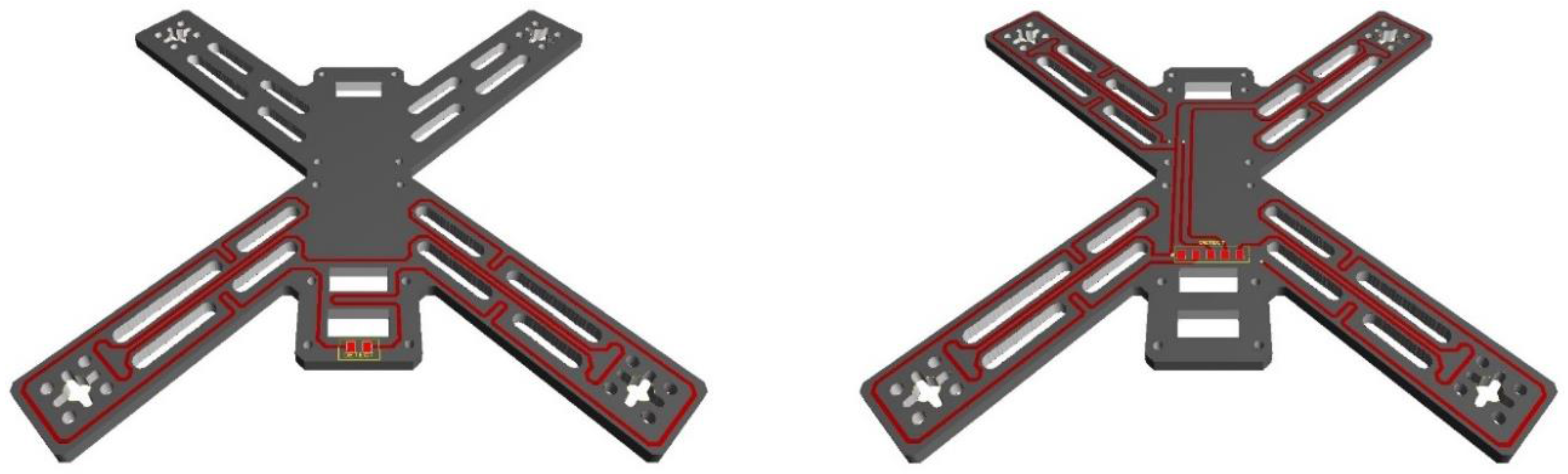
Figure 3.
Diagram of prototype dual drone system.
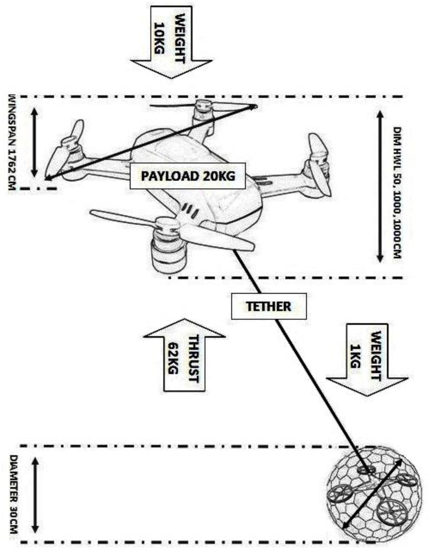
Figure 4.
Zwick Z010 machine (left), test specimen graph showing force vs. deformation (right).

Figure 5.
Magnified image of mesh layers (left), enameled copper necking (right).

Figure 6.
xFrame CAD and builds (left), +Frame CAD and builds (right).

Figure 7.
xFrame rotor direction (left), +Frame rotor direction (right). Where red arrows show direction of flight, black arrows show rotor direction.
Figure 7.
xFrame rotor direction (left), +Frame rotor direction (right). Where red arrows show direction of flight, black arrows show rotor direction.

Figure 8.
Flow diagram of flight controller response to motor arm damage.
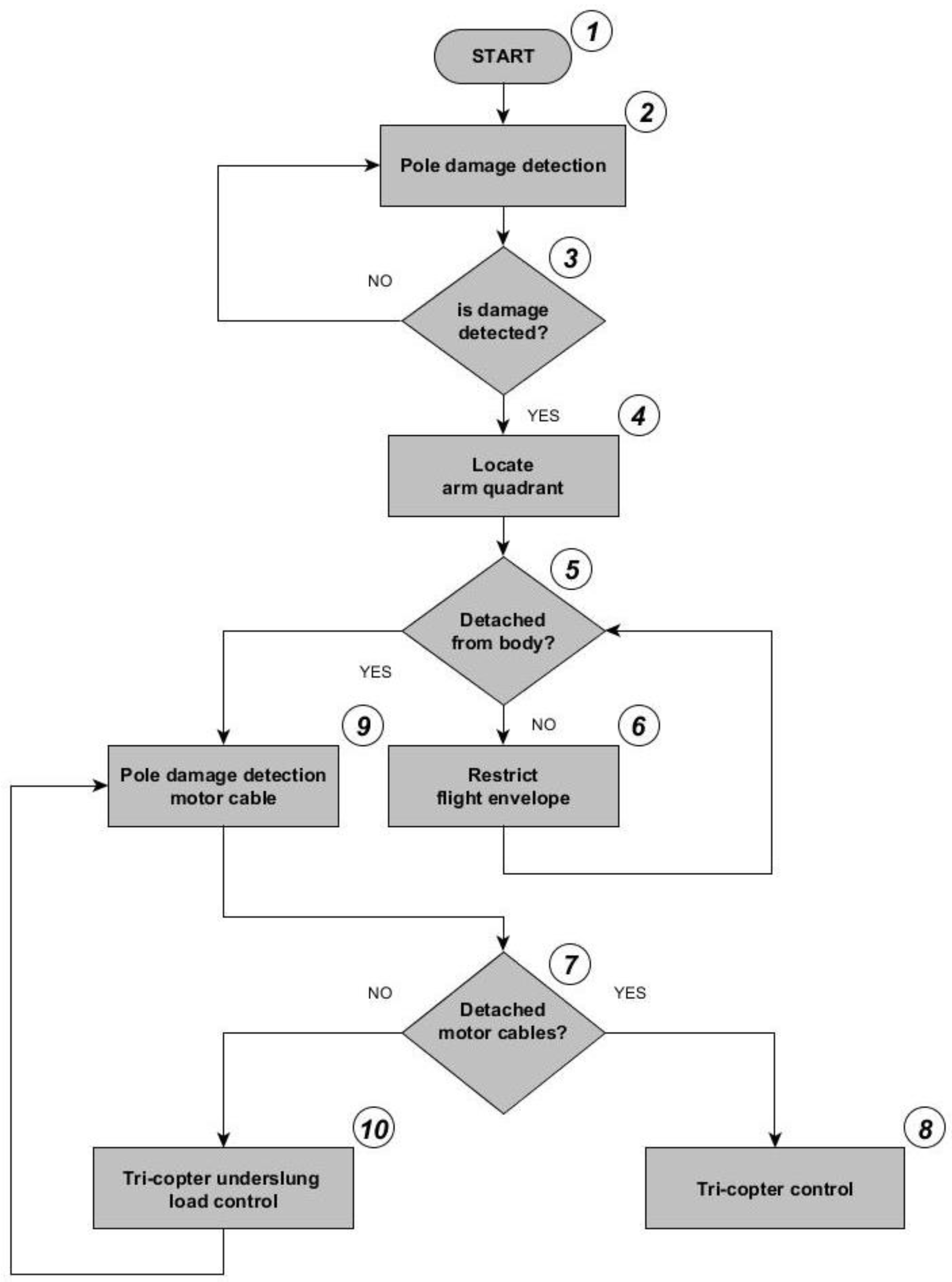
Figure 9.
Telemetry flight data of damaged +Frame, throttle gain and altitude with peak altitude.

Figure 10.
Telemetry flight data of damaged +Frame, pitch and altitude.

Figure 11.
Telemetry flight data of damaged +Frame, roll and altitude.

Figure 12.
Telemetry flight data of damaged +Frame, yaw and altitude.

Figure 13.
Master drone prototype build in progress.

© 2018 by the authors. Licensee MDPI, Basel, Switzerland. This article is an open access article distributed under the terms and conditions of the Creative Commons Attribution (CC BY) license (http://creativecommons.org/licenses/by/4.0/).
Share and Cite
MDPI and ACS Style
Bowkett, M.; Thanapalan, K.; Constant, E. Failure Detection of Composites with Control System Corrective Response in Drone System Applications. Computers 2018, 7, 23. https://doi.org/10.3390/computers7020023
AMA Style
Bowkett M, Thanapalan K, Constant E. Failure Detection of Composites with Control System Corrective Response in Drone System Applications. Computers. 2018; 7(2):23. https://doi.org/10.3390/computers7020023
Chicago/Turabian StyleBowkett, Mark, Kary Thanapalan, and Ewen Constant. 2018. "Failure Detection of Composites with Control System Corrective Response in Drone System Applications" Computers 7, no. 2: 23. https://doi.org/10.3390/computers7020023
Note that from the first issue of 2016, this journal uses article numbers instead of page numbers. See further details here.