Hardware-Assisted Secure Communication in Embedded and Multi-Core Computing Systems


1
Department of Electrical Engineering, COMSATS Institute of Information Technology, 54000 Lahore, Pakistan
2
Department of Computer Science and Information Systems, California State University San Marcos, San Marcos, CA 92096, USA
3
School of Mathematical and Computer Sciences, Heriot-Watt University, Edinburgh EH14 4AS, UK
*
Author to whom correspondence should be addressed.
Computers 2018, 7(2), 31; https://doi.org/10.3390/computers7020031
Submission received: 16 April 2018
/
Revised: 7 May 2018
/
Accepted: 12 May 2018
/
Published: 15 May 2018
(This article belongs to the Special Issue Multi-Core Systems-On-Chips Design and Optimization)
Abstract
:With the sharp rise of functionalities and connectivities in multi-core embedded systems, these systems have become notably vulnerable to security attacks. Conventional software security mechanisms fail to deliver full safety and also affect the system performance significantly. In this paper, a hardware-based security procedure is proposed to handle critical information in real-time through comprehensive separation without needing any help from the software. To evaluate the proposed system, an authentication system based on an image procession solution has been implemented on a reconfigurable device. In addition, the proposed security mechanism is evaluated for the Networks-on-chips, where minimal area, power consumption and performance overheads are achieved.
1. Introduction
Security and trust are becoming crucial design considerations for all contemporary embedded real-time systems as they are extensively put to use in crucial and decisive applications that require processing of data in a given time frame. Such embedded systems are now typically found in telecommunication devices, power grids, satellites, planes, automobiles, ATM machines, military equipment and medical diagnostic devices. Due to an increase in network connectivity and software content such devices are now becoming more prone to rapidly spreading security attacks through malicious software which were previously known to target servers, desktop systems and Internet connected devices [1].
Malicious software mainly targets embedded systems to get unauthorized access to critical data (such as confidential files and cryptographic keys), to modify sensitive information saved in the system’s storage unit and to reduce performance or drain power source (e.g., through execution of some valid tasks uselessly). These types of attacks are more commonly known as data confidentiality attacks, data integrity attacks, and performance degradation attacks, respectively. Embedded systems are usually more susceptible to these types of attacks due to two main features. Primarily, the reduced system resources and simplified processing cores architecture leave such systems prone to different kinds of physical attacks. Secondly, the ability to communicate to the outside world, without any built-in security mechanism, also expose such systems to software attacks leading to unauthorized accesses. Moreover, download or update of applications and other data by the embedded devices over insecure network connection or other mechanisms (such as unencrypted Wi-Fi and blue-tooth) always make them vulnerable to security attacks. More importantly, real-time embedded systems are designed and implemented in such a way that their main objective is to complete the specific task in the given time frame without engaging in the execution of irrelevant security applications such as an anti-virus software. In contrast to desktop computers that can afford software-based security mechanisms, resource-limited embedded systems require to use a considerable amount of their resources such as processing power and battery life to support such solutions. Furthermore, the existing solutions relying purely on software cannot detect unreported attacks without prior knowledge and regular updates of virus and malware definitions. Therefore, embedded systems must deploy such security countermeasures that are self-contained and have the ability to detect such attacks on the run without utilizing system’s dedicated resources.
In this paper, a new security mechanism has been proposed by isolating and positioning pivotal processing units in a secure zone to process sensitive data in a independent and secure way. The proposed secure zone-based solution operates independently without requiring modifications in the system software. The feasibility of the proposed mechanism is explained by implementing an authentication system on a reconfigurable device based on an image processing technique. It is further shown that the given system, when equipped with the presented security mechanism, can identify software-based attacks swiftly with nominal increase in area and power consumption. The scalability and functionality of the proposed solution is further verified by implementing it for the Network on Chip (NoC)-based communication systems and evaluating its performance, power consumption and area overhead when configured in different network sizes.
The paper has been arranged as follows: The existing hardware-based security mechanisms are outlined in Section 2. The key concept of managing data by the proposed security mechanism and its implementation details are discussed in Section 3. Section 4 deals with the assessment of the proposed security mechanism when utilized within a existing FPGA-based authentication system. The scalability and performance evaluation for the NoC-based communication systems has been discussed in Section 5 while conclusion is presented in Section 6 of this paper.
2. Related Work
Various security solutions have been presented in the literature based on the configurations of the system, functional specifications, types of attacks, and performance requirements. Physical attacks targeting embedded systems require direct access such as power consumption analysis through eavesdropping [2], timing analyses [3] and chemical-based attacks [2] but these kinds of attacks have not been covered here and we have targeted hardware-assisted security solutions capable of identifying software related attacks.
Presently, different hardware-assisted techniques related to secure processing of information have been presented ranging from cryptography, reference monitors, hardware virtualization [4] to dynamic information flow tracking (DIFT) [5]. Solutions related to reference monitors are based on comparing processor-executed code with a valid model whereas the security module works in parallel with the processing core as discussed by Kornaros et al. [6]. For instance, the secure reference monitors with hardware support [7,8,9,10] sense divergence in program execution on the run by analyzing system response against a predefined behavior in order to detect any attacks targeting data integrity. The static models are normally obtained through static analysis and profiling of the programs to be loaded on the system.
Yan et al. in [11] have presented a concept of hardware isolation for mobile devices which is based on disabling the dangerous hardware components when sensitive applications are running. They have not verified this approach by practically implementing it for a realistic system. Rathgeb et al. [12] presented a secure processing technique by implementing generic modules as secure blocks where interconnections among them can be reconfigured using run-time partial reconfiguration. Such approaches cannot be deployed where system switches rapidly between secure and insecure mode, as partial reconfiguration results in significant performance overhead.
Security systems based on cryptography such as encryption devices have been used extensively for the implementation of strong isolation. Thekkath et al. [13] provide a security mechanism at process level by isolating trusted process’s data and instruction code from untrusted and vulnerable processes. To prevent illegal extraction of information, dedicated tags are assigned to each process and cryptographic algorithms are used to encrypt the data and code. Similarity, Suh et al. [14] have presented an encryption-based security technique by isolating the processor resources from external memory unit and other untrusted I/O devices. They have implemented a security kernel within the untrusted operating system and secure context manager.
Hardware-assisted solutions based on DIFT techniques [5,15,16] are also quite capable to handle software related attacks. These solutions mainly rely on flagging data arriving from insecure input peripherals and then following the trail as the system processes the data. These kinds of solutions are based on making modifications in the source code of the application, system memory and the architecture. Such requirements have made these solutions unlikely choice to secure embedded systems. Furthermore, techniques achieving security through hardware virtualization [17,18,19] depend on dedicated software support more commonly known as “hypervisor” to execute tasks requiring security. Moreover, latest surveys [20,21] have presented that even these types of refined techniques are vulnerable to security breaches and constrained in terms of code and data memory. Therefore, it is very essential to come up with a new security solution that is capable of processing critical information in a secured manner with no or little help from the software running on the system.
Fiorin et al. [22] have presented a data protection module, for multi-core systems, to detect illegal accesses to specific blocks of the memory unit by verifying access rules and using address lookup tables. Similarly, another solution has been presented by Lukovic et al. [23] to detect buffer overflow-based attacks by including a dedicated security module within the network interface attached to each of the processing cores. Following the same pattern, Porquet et al. [24] have presented a security mechanism for network on chip architectures with a shared memory unit. Their basic idea is to segregate several applications based on the required trust level and process information securely using both dedicated software and hardware modules. More recently, Wassel et al. [25] proposed a low-latency and non-interfering security mechanism, called SurfNoC, to protect system against side-channel attacks such as timing analysis. This is achieved by maximizing temporal and spatial isolation of different communication flows in the system through network scheduling in a wave manner. Wassel et al. extended this work [26] and proposed a partitioning mechanism through packet scheduling to pass packets between different domains with lower latency. Grammatikakis et al. [27] have proposed a self-contained NoC firewall within the network interface by validating the memory requests against the predefined set of rules. Hu et al. [28] have also presented a similar solution by incorporating access rules verification and authentication mechanism for certain regions of the memory units. In our previous work [29], we have presented an identity and address verification-based security module for multi-core systems in order to detect security attacks and stop illegal accesses to the memory. Kornaros and Leivadaros [6] have proposed a system level framework for updating firmware in interconnected embedded devices by classifying data types to transmitted, processed and stored data and tailoring a solution for each type of data by encryption or isolation.
The reference monitoring and DIFT-based security solutions either require changes in main hardware resources (such as processor and memory architecture) or partial software support which are not ideal for embedded systems especially for battery operated devices where power consumption and available resources are one of the main design concerns. In one of our previous work [30], it is shown that security mechanisms that rely on cryptography are not realistic and scalable for multi-core based SoC devices due to their limited resources, high performance and power consumption overheads. In contrast, our proposed security solution does not require modifications in the processor or memory architecture, operates independently without any help from software side and bears minimal performance overhead for NoC-based systems [31]. Security mechanisms for NoC-based multi-core systems (such as [22,24,27,28,29] have only been designed specifically for shared-memory architectures and provide protection to memory units only whereas our proposed solution can be used to isolate any processing block ranging from memory controllers to other I/O peripherals. Similarly, the hardware-based security solutions, as discussed by Yan et al. [11], are based on disabling some unreliable processing cores when sensitive applications are running. For real-time embedded systems, such approaches are clearly not feasible. On the other hand, our proposed security mechanism works alongside unreliable processing cores without disabling them. Furthermore, these existing solutions target specific security attacks whereas our hardware-assisted secure mechanism can handle data integrity, confidentiality and denial of service attacks as well.
3. Design Approach and Architecture
Software attacks have become increasingly widespread and a buffer overflow is one of the major causes of security outbreaks. Although buffer overflows may arise unintentionally due to common programming errors, it is one of the most common types of software attacks targeting data integrity. In the case of buffer overflow-based attacks, the additional data may point to the malicious code designed to execute new instructions and initiating specific tasks on the system under attack. This research work is based on the hypothesis that the buffer overflow-based attacks can be addressed through dedicated security modules. The main aim of this research is to explore and develop a generic and scalable security hardware module for multi-core systems that can detect buffer overflow-based attacks, identify the compromised processing cores under attack and stop its propagation in order to keep the system secure and infection free.
This section explains the design steps of our proposed security solution along with its basic architecture layout considering a conventional embedded system based on a FPGA device. Normally an embedded system consists of a microprocessor, Input/output devices, memory unit and other peripherals which are essentially required to run the given task. The main objective of designing a hardware-assisted security module is to restrain the unreliable hardware modules from accessing trusted processing units when critical tasks are under execution.
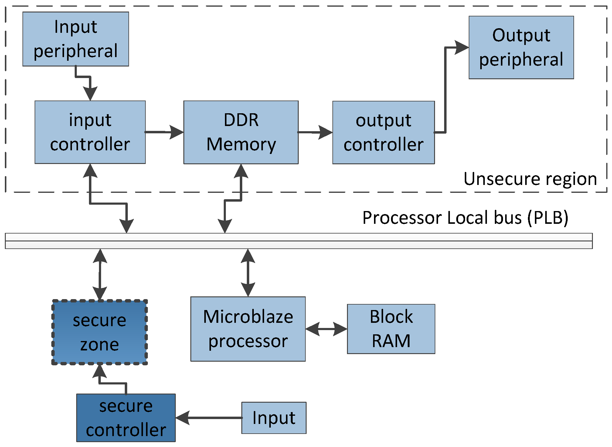
In order to execute the critical tasks in a protective environment, a secure zone has been designed whereas its functionality has been tested for a FPGA-based embedded system and a NoC-based multi-core architecture as well. The basic concept is to adjust processing blocks requiring security in an isolated environment such that they are only accessible via a security checking module. The block level implementation of a conventional embedded system accommodating a secure zone is presented in Figure 1. The processing blocks executing or storing critical data are to be implemented separately inside the secure zone from untrusted processing blocks (such as peripherals and controllers).
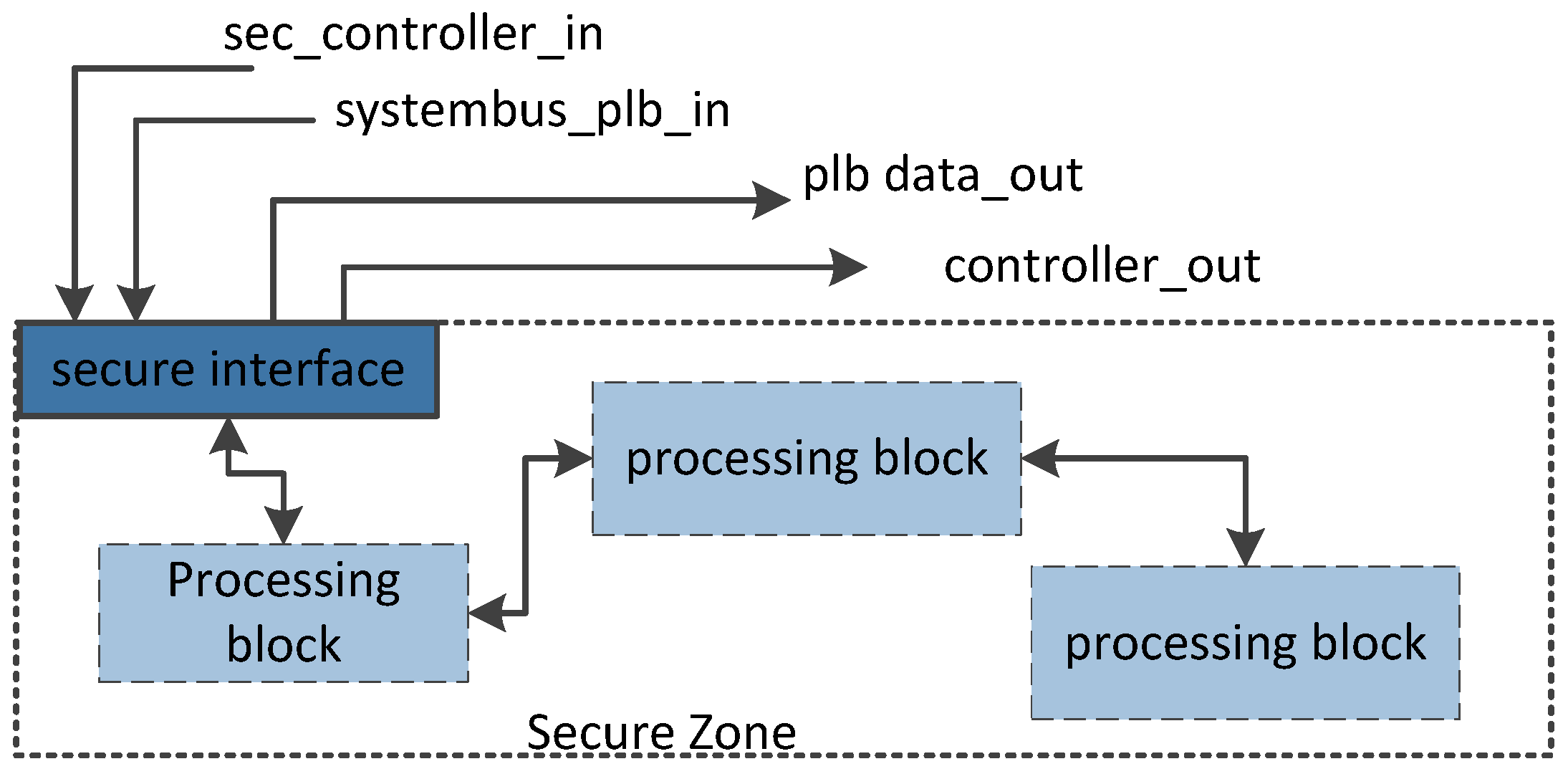
As shown in Figure 1, the secure zone communicates directly with the Processor Local Bus (PLB) and the secure controller only. The permission is granted by the secure zone after confirming the access control rules (e.g., write access only, read access only, and/or both write and read access). These access rules are initialized at the time of configuration. The processing blocks implemented inside the secure zone are only accessible by the untrusted processing blocks via specialized interface as indicated in Figure 2.
The control input, sec_controller_in, to the secure zone is produced by the secure controller which operates independently and has no linkage with the other processing blocks or software running on the system. On the contrary, the second control input, systembus_plb_in is produced by PLB which is managed directly by the task/software under execution. In order to access the processing blocks within the secure zone, the secure interface must receive the same access control signals from both of the control inputs.
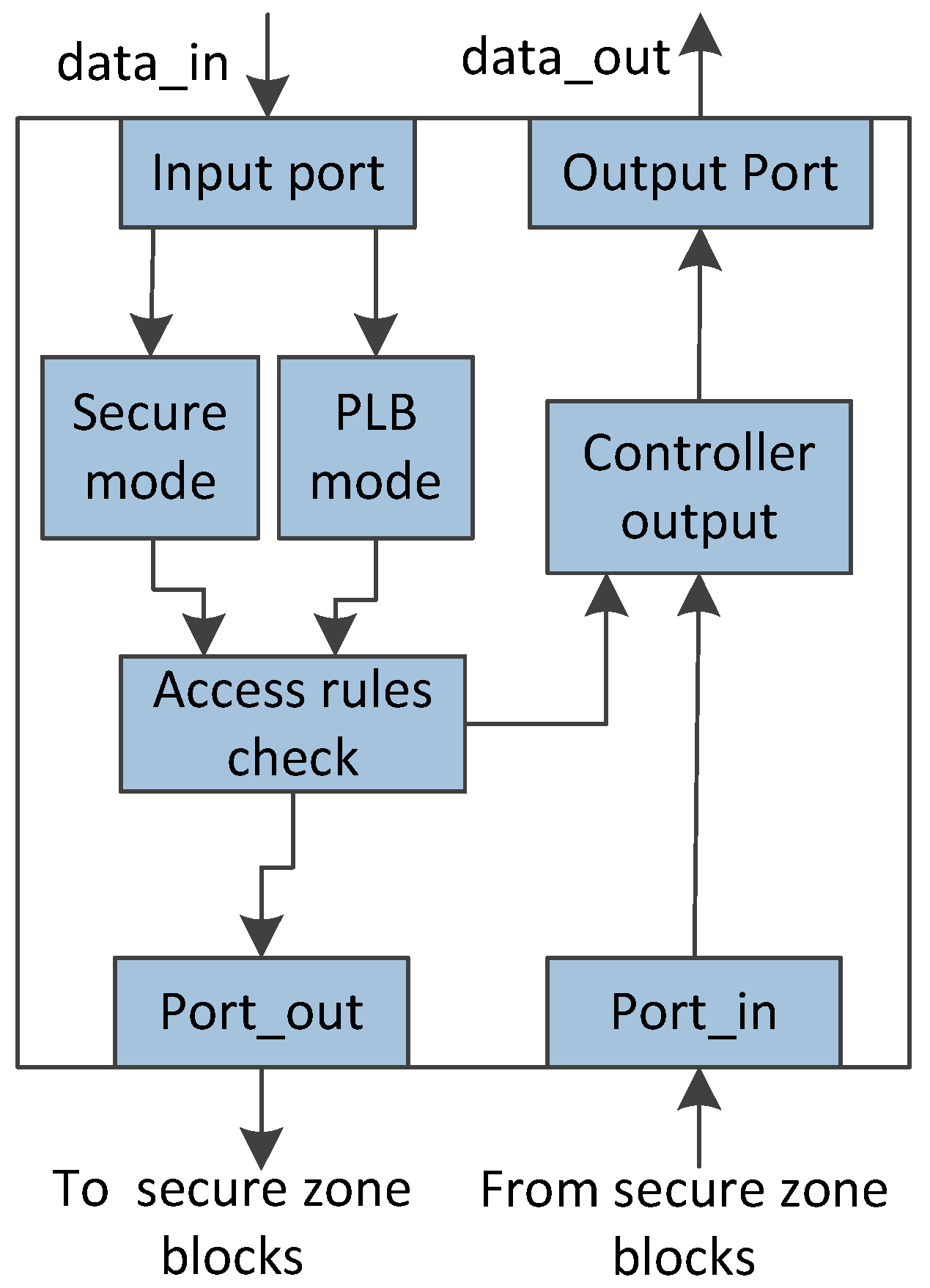
The internal working of the interfacing module is presented in Figure 3. This module is responsible for verifying the incoming data before authorizing access to the processing blocks within the secure zone. For instance, in order to update the storage module within the secure zone, the software will generate signal requesting write access whereas the user is also required to generate the same signal using secure controller. In the event of any security attack, the secure interface will fail to verify the access control signals and in that case an alert signal will be generated, preventing access to the secure zone processing blocks. This has been further elaborated in the next section.
4. FPGA-Based Embedded System
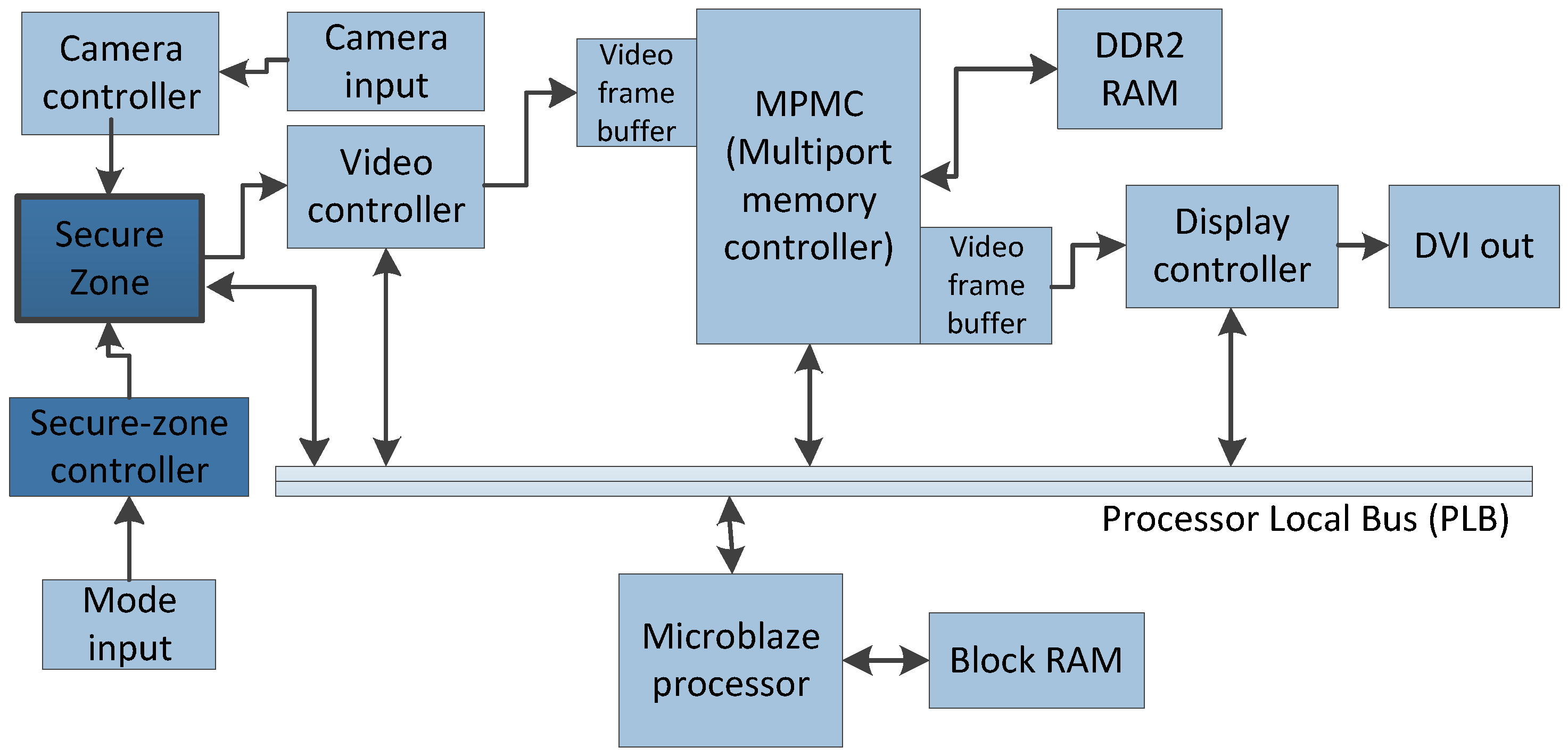
As a proof of concept, the proposed security mechanism is implemented and tested by incorporating it in a signature-based authentication system [31] as shown in Figure 4. Such systems have many applications where security is the primary concern. For instance, banking institutes can use it to validate signatures automatically on the checks. The prototype design has been implemented on a specialized FPGA device, Spartan-3A DSP Video Starter Kit (VSK), which has dedicated hardware resources to process video data in real-time. This VSK comes with a reference design which is customized to implement an authentication system according to our proposed solution with the help of Xilinx Embedded Development Kit (EDK) [32].
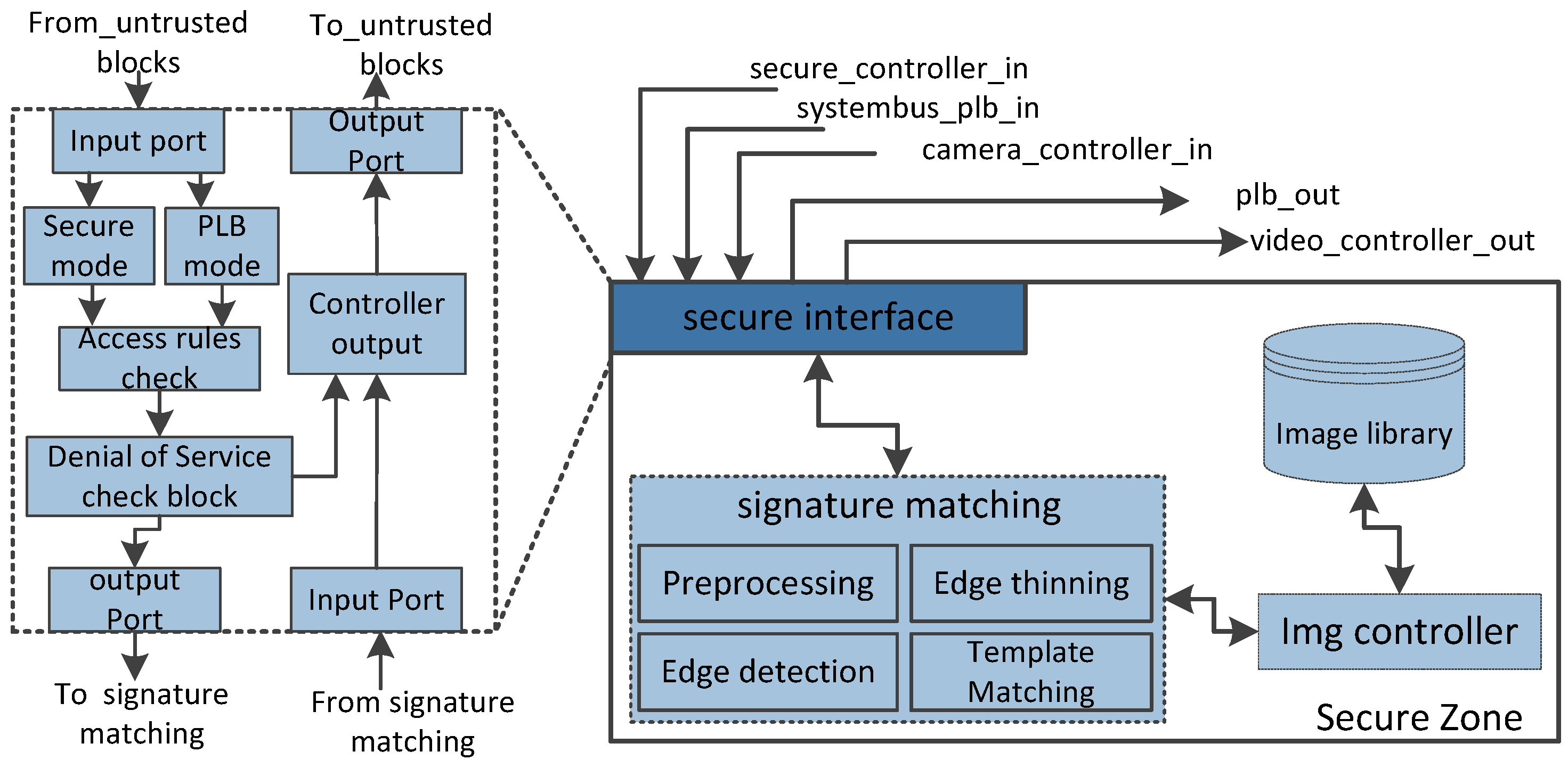
The secure zone has been implemented for the given authentication system as shown in Figure 5. Here, the image library block is used to store images of valid signatures whereas the signature matching block is the primary module that has been used to process signature images arriving from the camera controller and perform verification based on template matching technique. Considering the sensitivity of the data, the image library and signature matching block have been placed inside the secure zone to perform authentication procedure in a protected environment.
The processing blocks (signature matching and image library), handling sensitive images, are placed separately from untrusted blocks (e.g., DDR2_RAM, PLB, display controller). In general, the signature matching block performs authentication whereas the image library is essentially a database of reference images. The blocks placed within this secure zone are accessible to the untrusted blocks after performing access rules checks. In order to access image library or signature matching block, the secure-zone controller and the PLB must pass the same access rights signals. After successful verification by the secure interface, the camera_controller_in and systembus_plb_in signals are transferred to the signature matching block implemented inside the secure zone. For instance, to update images in the image library, software will generate write access request through systembus_plb_in and at the same time it is also required to have a write access request from secure_controller_in input signal. In the event of any security attack, the access control signals will mismatch and an alert signal will be generated, stopping access to the secure zone. This is achieved through the secure interface as shown in Figure 3. The permission is granted by the secure zone after confirming the access control rules (e.g., write access only, read access only, and/or both write and read access) from both of the control inputs are identical. As the attacker does not have access to secure interface, even trying to send an access request just through PLB will be denied as secure module access control signals indicating no access or a different authorized access to the user such as read access instead of write access.
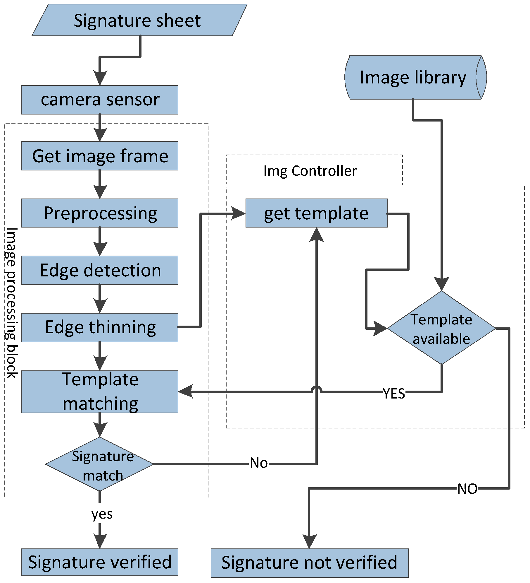
The flowchart, as shown in Figure 6, is being implemented inside the secure zone to perform signature matching by verifying the incoming image frames from the camera sensor. The user signs on the specific sheet, which is placed in front of the camera at the fixed distance. After verifying the access rights through secure interface module, the system performs signature matching by following the steps as presented in this figure.
4.1. Security Effectiveness
The vulnerabilities in the software, executing on an embedded system, can be exploited at run-time by different security attacks. Usually, the application data is susceptible to attacks when system resources are accessible through untrusted communication medium. Typical examples are buffer overflow attacks [33], in which a part of the code is modified and the return address is replaced which in turn transfer the control to another region pointing to a harmful piece of code. As per the Sourcefire report [34], 14% of all vulnerabilities and 35% of critical ones in the last two decades are buffer overflow attacks. For this purpose, the effectiveness of the proposed security mechanism is evaluated by analyzing the system behavior under various buffer-overflow-based attacks.
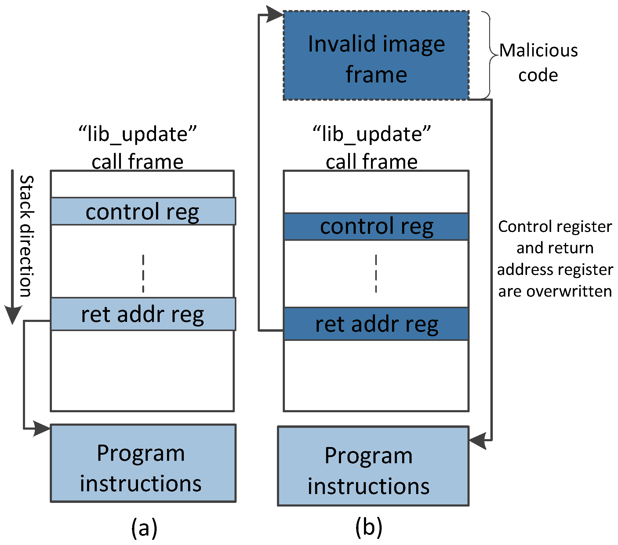
To modify the image library contents, we instantiated a buffer overflow attack as shown in Figure 7. During application execution, the control register is overwritten at the stack frame and additional data is inserted for illegal branch instruction, which in turn overwrites the return pointer of the given function call. Therefore, the control flow is switched to the location where illegal image frame has already been placed by the attacker. Using the standard interface, without any protection mechanism, the image library is modified illegally through buffer-overflow-based attack. On the contrary, when the secure zone is enabled with secure interface, the attack alert signal is generated successfully.
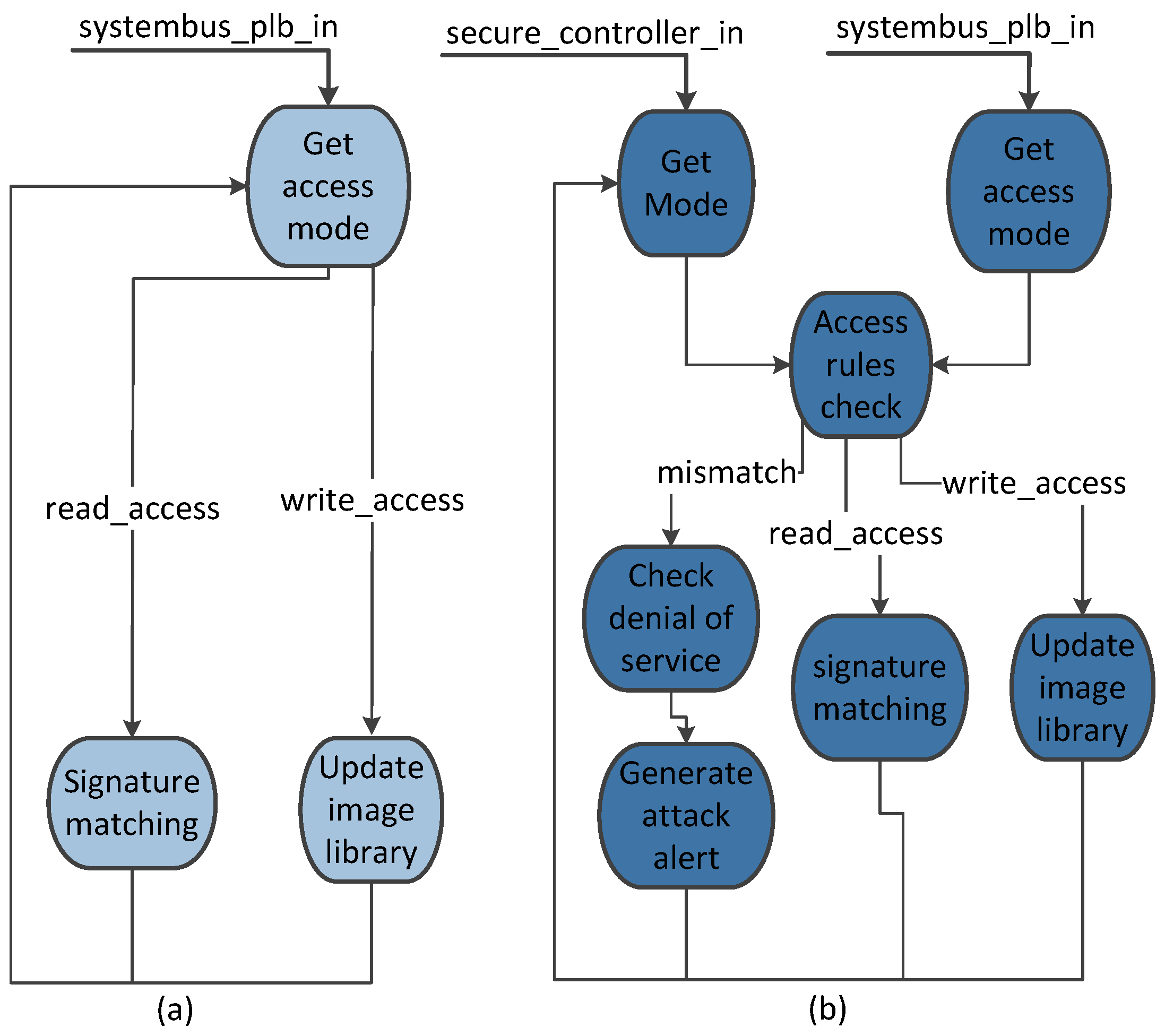
Beside handling buffer-overflow-based attacks that target integrity of the data, our security mechanism is capable of detecting data confidentiality and denial of service attacks as well. For instance, if the system software is get infected with malware and the attacker tries to extract the data, the secure interface will terminate the data flow as the sensitive information from the secure zone can only be extracted by providing the identical access rights through the secure-zone controller and PLB modules as explained earlier in Section 3. Similarly, denial of service attacks are avoided by monitoring the incoming requests and granting access to the secure zone modules when required such as updating the image library module implemented within the secure zone. Although the modules inside the secure zone can only be activated through secure-zone controller, the attacker can generate repeated requests deliberately to slow down the system performance that ultimately results in battery drainage. In our security mechanism, we have monitored the access rights, being generated by the PLB data_in, through a specialized counter for a specific period of time. For instance, if the attacker generates unnecessary accesses to the secure region modules continuously then such requests will be filtered out. The control flow of the system with and without secure zone implementation is presented in Figure 8. Without secure zone, the control flow as shown in Figure 8a will be followed and the image library will be updated by the software by transferring the write_access control signal. In the event of a buffer overflow, as mentioned earlier, the attacker can modify the access rights within the systembus_plb_in input signal and acquire unauthorized access to the image library block.
Consequently, the access signal is modified illegally through a buffer-overflow-based attack and return address of the function is updated leading to the malicious code. In this way, the images within the image library block are updated illegally without any authorization. Alternatively, the control flow as presented in Figure 8b will be followed when secure zone-based solution is in use. In our proposed security mechanism, the access control signal extracted from the systembus_plb_in input will be compared with the control signal derived from the secure_controller_in input. In the case of buffer-overflow-based attack, the access control signal generated by the software is overwritten but the secure-zone controller output remain unaffected as it has direct link with the software. When control flow comes to the “access rule check”, stage, a mismatch is successfully discovered and the secure interface of the secure zone alerts the system.
4.2. Area and Power Consumption Overhead
In order to evaluate overhead of the proposed solution, the area and power consumption has been measured in two steps. In the first step, the authentication system is implemented without secure zone. In the second step, after testing and functional verification of the basic system, the secure zone (secure-zone controller and interface) is implemented. Xilinx Synthesis Tool (XST) is used to generate the area and power consumption overhead results at both steps.
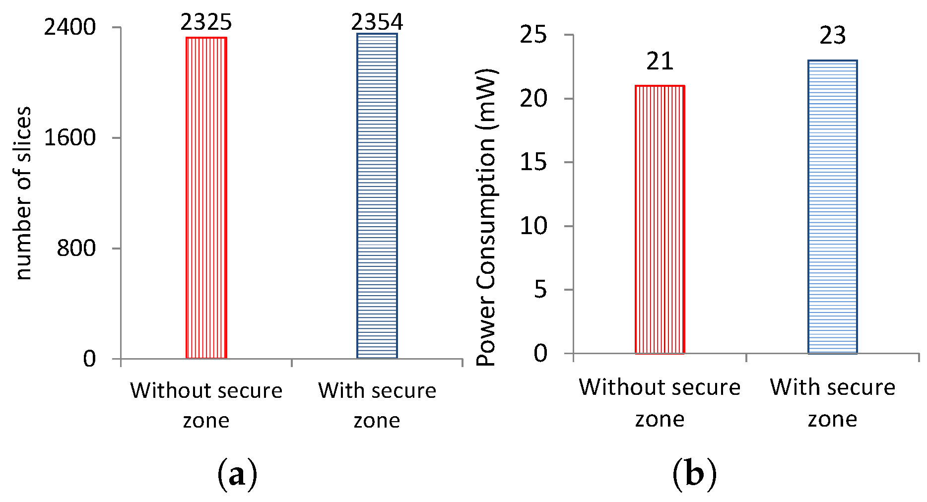
For fair comparison, the area overhead results are obtained by disabling the Block RAM (BRAM) and DSP blocks for the secure interface and secure-zone controller implementation. XST is configured to use flip flops and lookup tables only during synthesis phase. In our case, the area overhead is calculated by measuring number of slices utilized when the modified system, equipped with the proposed security mechanism, is synthesized for the given FPGA device. As presented in Figure 9a, our proposed solution has incurred an area overhead of 1.23% only.
Today’s FPGA-based embedded systems have increased substantially in computational power and capacity which has resulted in significant rise in power consumption. Efficient management of system resources with minimal impact on the power consumption has now become one of the prime design concerns. For this purpose, we have measured the increase in dynamic power consumption of the modified system when enabled with the secure controller and interface as compared to the standard system. The XPE (Xilinx Power Estimator) tool [35] has been to measure the power consumption overhead. As indicated in Figure 9b, our proposed security mechanism has resulted a rise of 2 mW in power consumption as compared to standard design with no dedicated security modules.
4.3. Performance Evaluation
The performance of the given system always gets affected whenever a dedicated hardware module is included serially within the processing blocks. In order to assess how the proposed security solution impacts the execution time of the system, the performance overhead is calculated for two different test cases.
In the first case, we have evaluated the delay introduced by our proposed solution in the image processing-based authentication system. The secure controller and secure interface have been implemented in a pipelined architecture to minimize their impact on the system execution time. To measure the delay, at first we have synthesized our design with and then without security mechanism. The timing information is produced with the help of XST. The time taken by the secure zone to update image library, utilizing secure interface, is defined as the secure execution time (SET) and it is measured by using Equation (1).
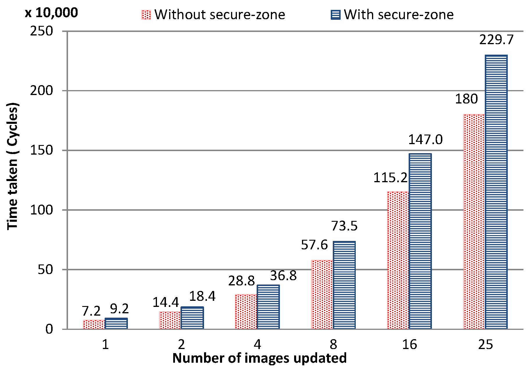
where and are the worst-case times required by the standard interface and the secure interface respectively to generate output signals. Normal execution time (NET) is defined as the total number of clock cycles required to update the image library using standard interface without any security mechanism. The performance overhead in terms of total number of cycles required to update image library through secure interface is presented in Figure 10. It is observed that the delay introduced by our security mechanism remains constant and it is directly proportional to the number of images being updated. For instance, the secure interface induces 21.64% increase in the total number of cycles to update 25 images as compared to the standard interface.
In the second case, we have implemented the proposed solution for a NoC-based multi-core systems which has been discussed in detail in the next section.
5. NoC-Based Communication Architecture
NoC-based communication architectures in multi-core systems have become apparent as a promising substitute to shared bus architecture and have been investigated extensively in terms of system performance, network topologies, application-specific implementations and routing mechanisms. Security aware architectures for such multi-core systems have come forth lately in the research literature as the network connectivity and complex embedded cores have also made these systems more susceptible to the software-based attacks. The protection of sensitive information has become the main design goal, especially in shared memory-based architectures where, without required protection, the application data can be modified by the compromised processing cores through illegitimate access to the security critical areas of the memory.
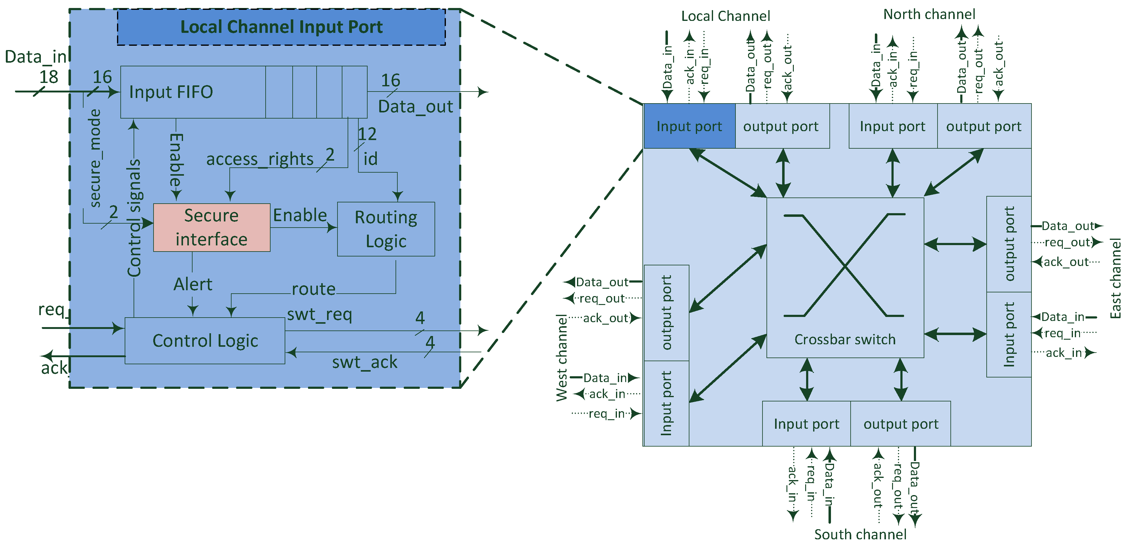
In order to determine the scalability of the proposed solution, we have implemented the secure interface for NoC-based communication architecture. A standard five-port router is designed for this purpose and the secure interface unit is embedded into the router’s local input port as shown in Figure 11. It is assumed that each router has secure_mode input signals attached to its local channel’s input port. The processing core requiring higher level security can be configured to such routers whereas normal cores can be attached to standard routers. In this way, the trusted processing cores can be isolated from other untrusted cores.
The processing core is attached with the local channel of the router and other four channels are connected with its adjoining routers. As the processing core communicates with other cores through the local channel, it is the perfect place to configure secure interface in order to verify the access rights and detect any compromised packet as soon as it is injected. The packet being injected comprises four flits, which will be stored at the buffer of the input port. XY routing algorithm and a cut-through flow control mechanism has been implemented in order to route the packet flits. The header flit stores the address of the source and destination cores along with the access control rules (e.g., write access only, read access only, and/or both write and read access). The secure interface module receives access_rights input from the header flit of the packet and verifies it with the secure_mode input as discussed earlier in Section 3). If both inputs are correctly verified then an enable signal is generated and in case of any mismatch an alert signal will be generated by secure interface module for further action. After getting the alert signal, based on the security policy, the manager core can either disable the compromised core or reset the system to its default configuration.
For hardware resources evaluation, the router is designed and developed for a Xilinx Virtex-7 FPGA where target technology is 28 nm. To evaluate the impact of the secure interface on the router, the increase in area and power consumption is measured in two steps. At first, a standard router without secure interface is synthesized and configured for 16 and 32 bit channel width, and network sizes of 16, 64 and 256 nodes in mesh topology. In the second step, after implementing and verifying the functionality of a standard router, the secure interface module is embedded in the local input port of the router. The modified router is again synthesized for the same channel widths and network configurations, using XST, as mentioned earlier.
5.1. Area and Power Consumption Overhead
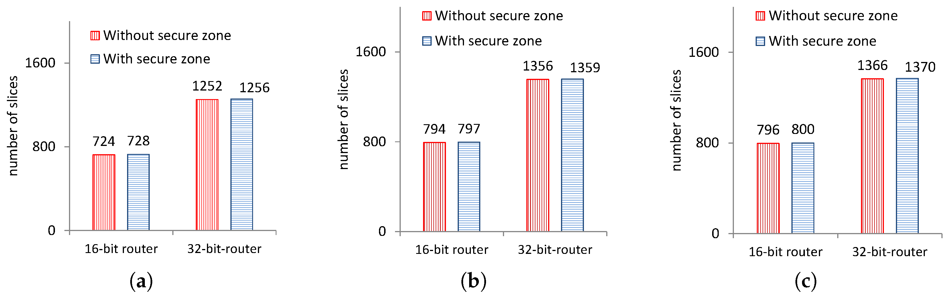
Area overhead is calculated by observing increase in the slice utilization when the router is enabled with the secure interface and synthesized and compared to a standard router without the security feature. The slice utilization of various configurations of the router has been presented in Figure 12. In our case, the secure interface has presented an area overhead of four slices only when configured for different number of nodes.
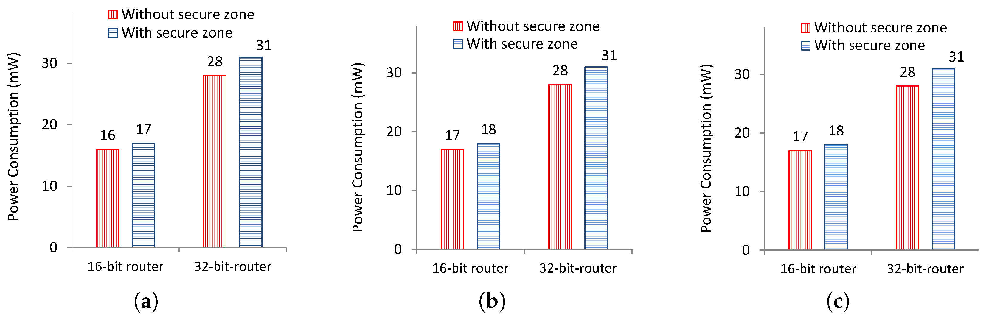
Similarly, the power consumption overhead has also been measured. In our case, the main focus is in the power consumed by the when the secure interface enabled router is in operation. The increase in power consumption has been measured by calculating the dynamic power consumed by modified router and compared to the same router architecture without secure interface. This overhead is evaluated using the XPE tool [35]. As illustrated in Figure 13, the power consumption overhead remains constant for different network sizes. This is expected as the secure interface module working does not depend on the network size.
5.2. Performance and Energy Evaluation
Beside measuring the area and power consumption overhead at router level, hardware level changes in the router architecture have certain impacts on the overall system performance, therefore it is very critical to evaluate the performance and energy consumption overhead at the network level as well. Firstly, to evaluate impact of the secure interface on the performance of each router, the propagation delay of the modified router is calculated by using Equation (2).
where and are the respective propagation delays required by a router to generate output when configured without and with a secure interface module. The is the propagation delay, measured in clock cycles, incurred by the standard router to transmit one complete packet from one input port to the output port. To get performance evaluation results, a cycle accurate interconnection network simulator [36] is used. The secure interface is configured inside each router using the simulator for a mesh network of , and nodes with XY routing scheme and virtual cut-through packet switching technique with a packet consisting of four flits. The simulator is configured to use first 2000 cycles as warm-up period and run the experiment up to 200,000 cycles. The simulator is then set up to inject packets at different rates until the network reaches to a saturation point where injection of new packets is not possible in the system unless existing packets are processed. During warm-up period the simulation results are ignored and collected for active cycles only.
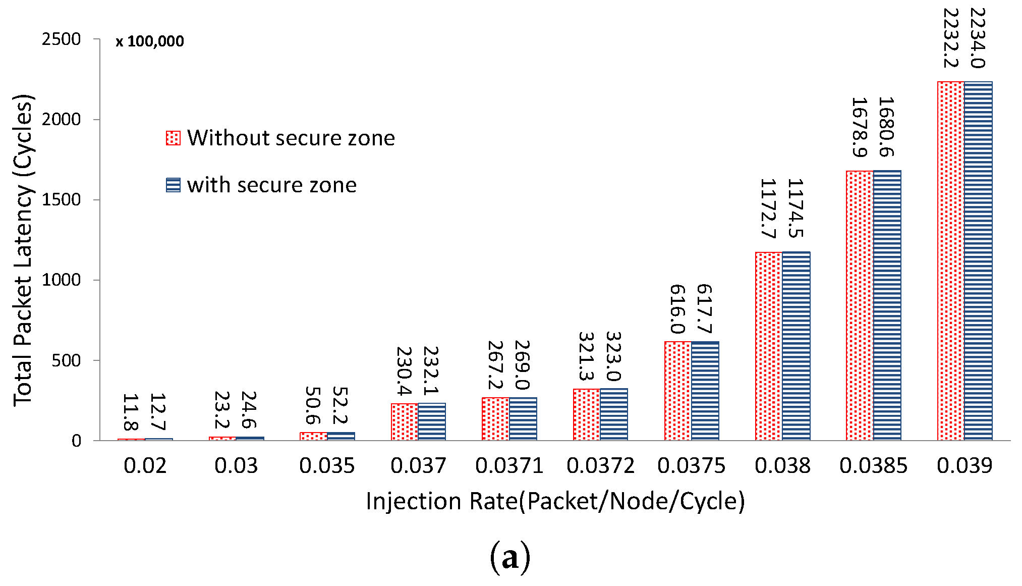
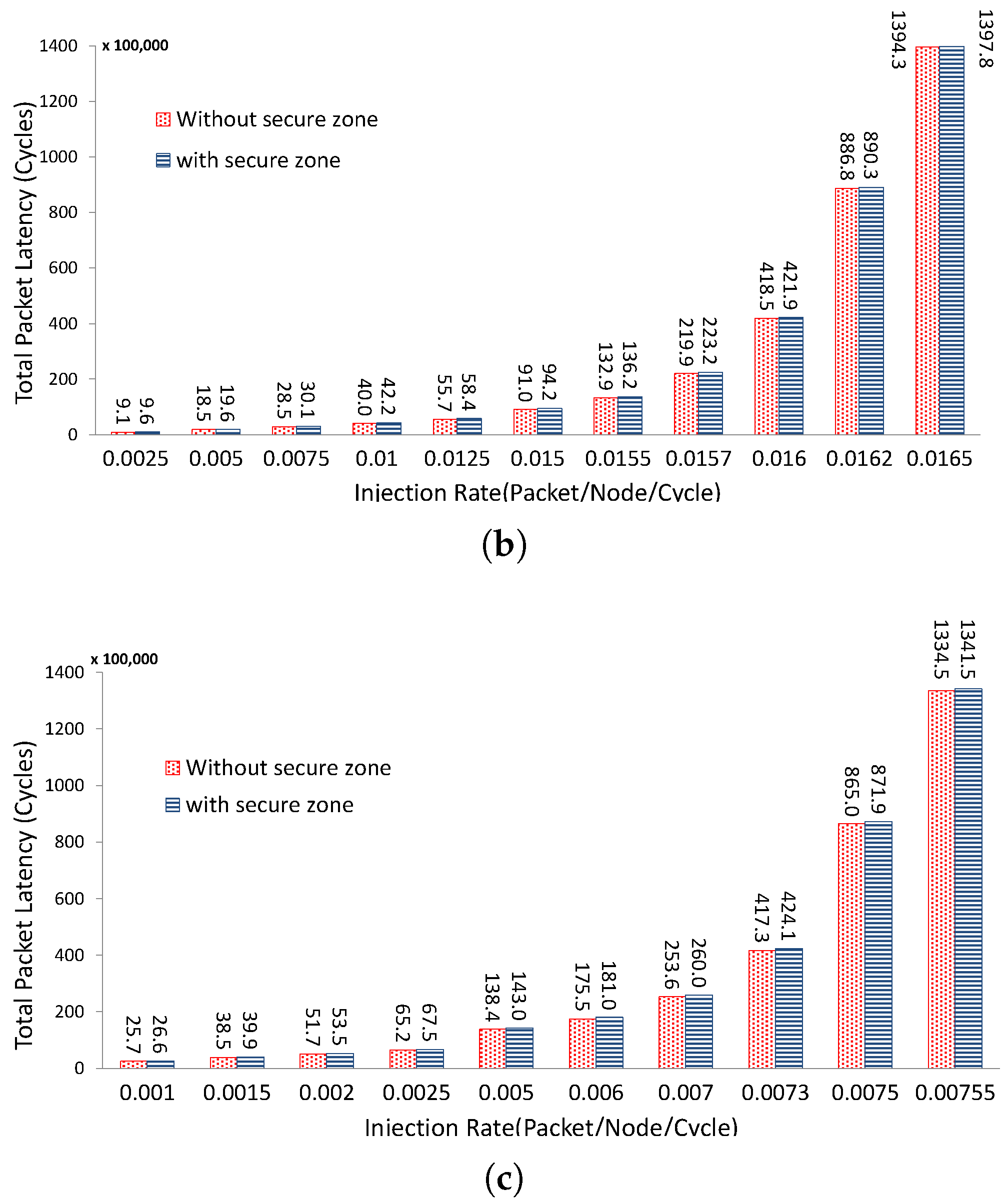
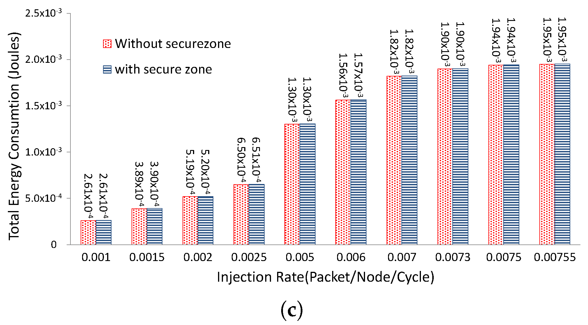
Total packet latency has been used to measure performance overhead which is the number of clock cycles required for all the injected packets to reach their corresponding destinations. At first, the results are collected by measuring the packet latency for the standard router architecture. After getting the base results, the router configurations are adjusted to incorporate the propagation delay presented by secure interface block.
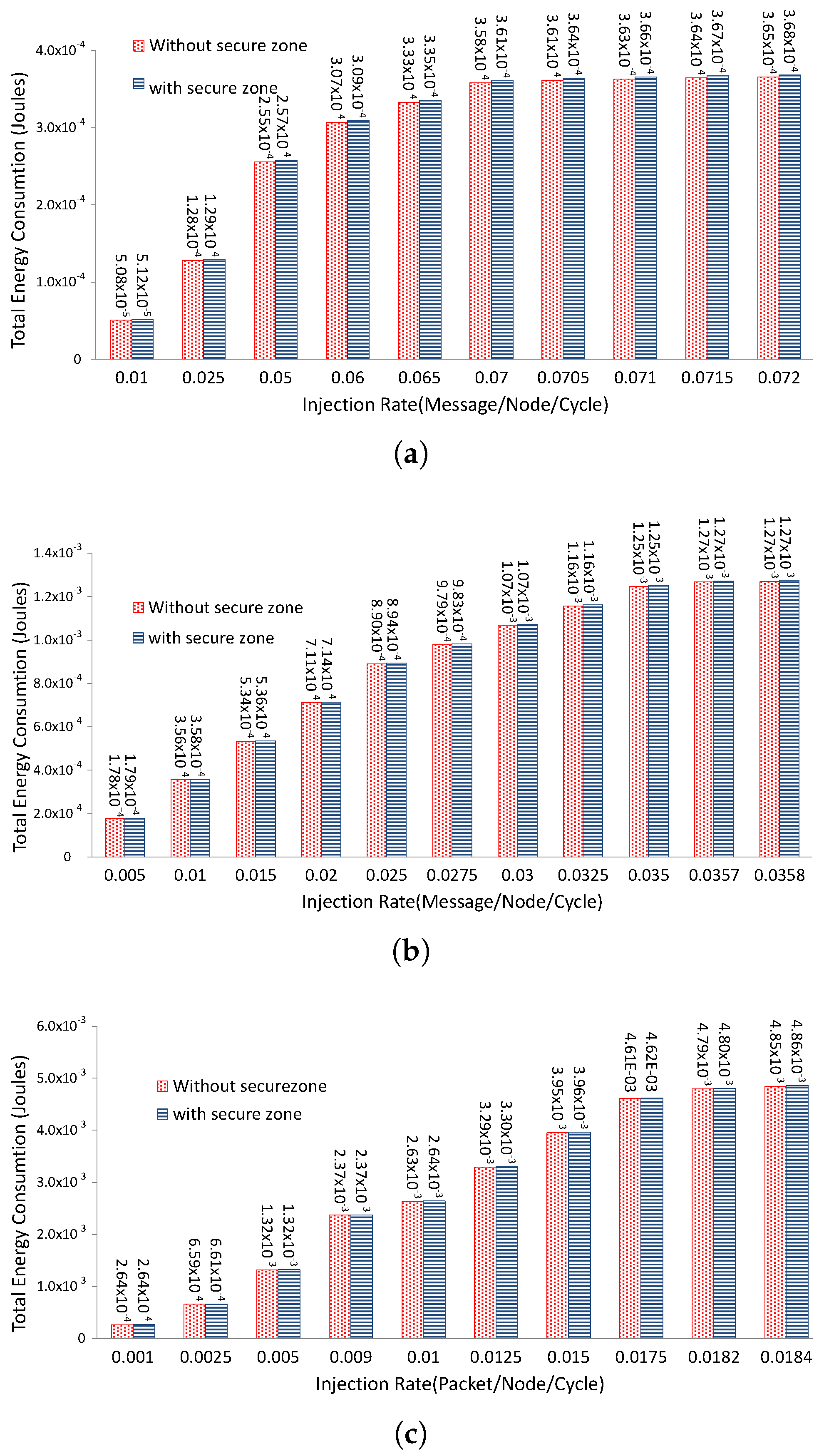
Network energy consumption overhead is measured by configuring the Orion power model [37] within the simulation framework. In the first step, extra energy required by the secure interface module within the router is measured with the help of XPE tool. In the second step, to get the total network energy consumption overhead, the simulator framework is modified to add the secure interface module energy overhead for each router.
The network energy consumption and packet latency are calculated by first simulating the network in various network configuration settings with and without the secure interface. For this experimental evaluation, we have used both various traffic patterns as explained below.
Three different synthetic traffic patterns are used for the simulations: uniform, transpose and hotspot traffic patterns.
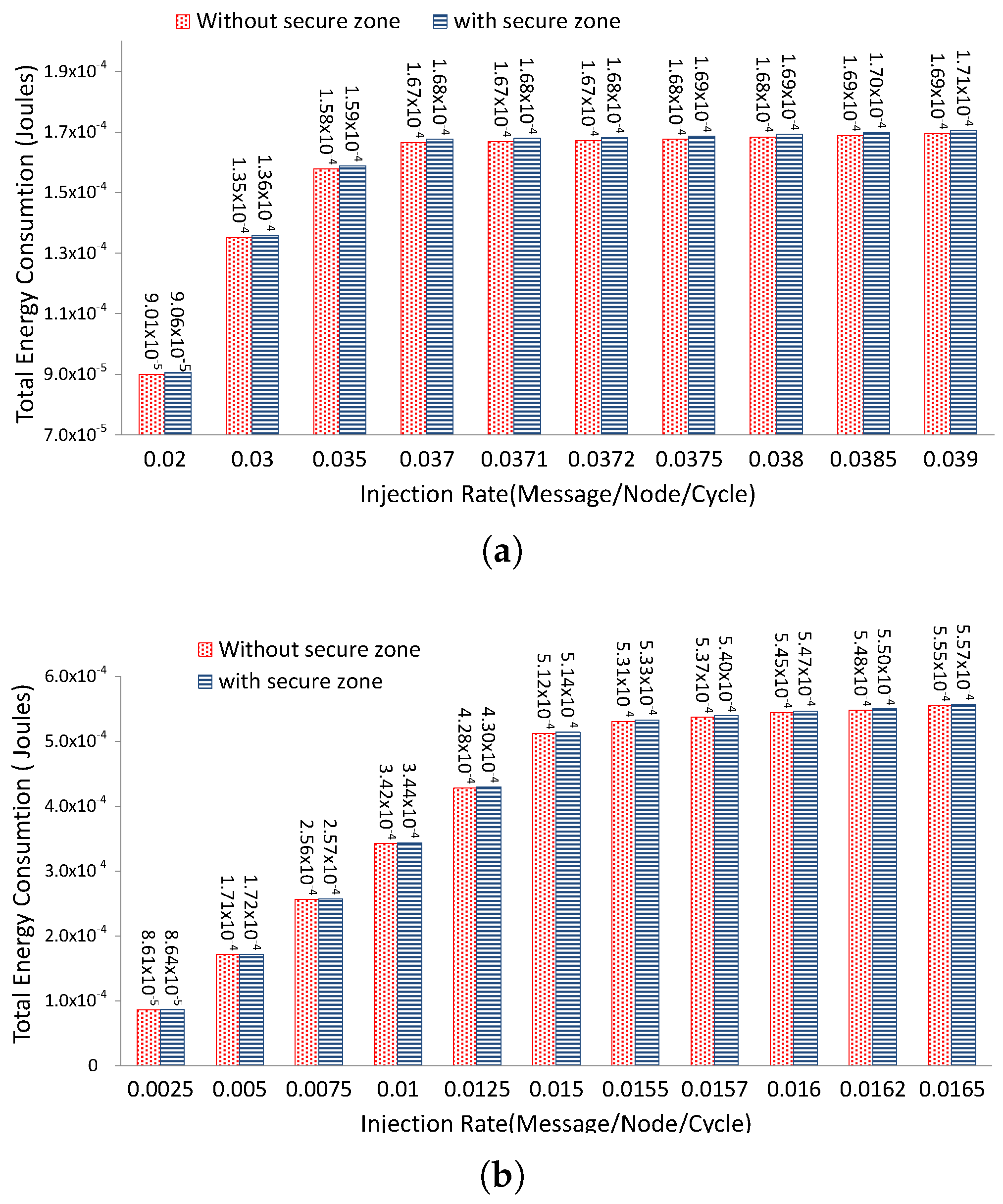
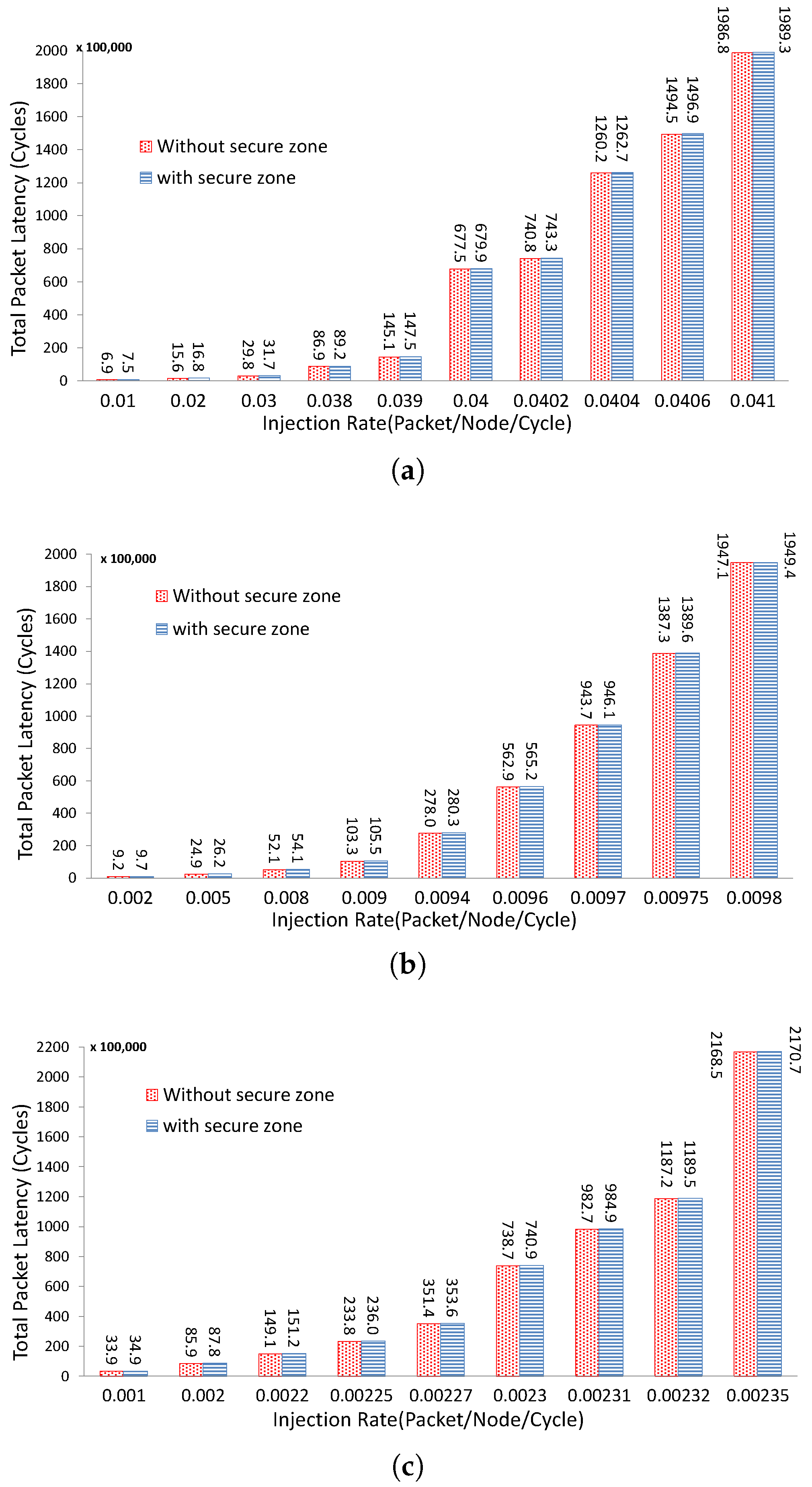
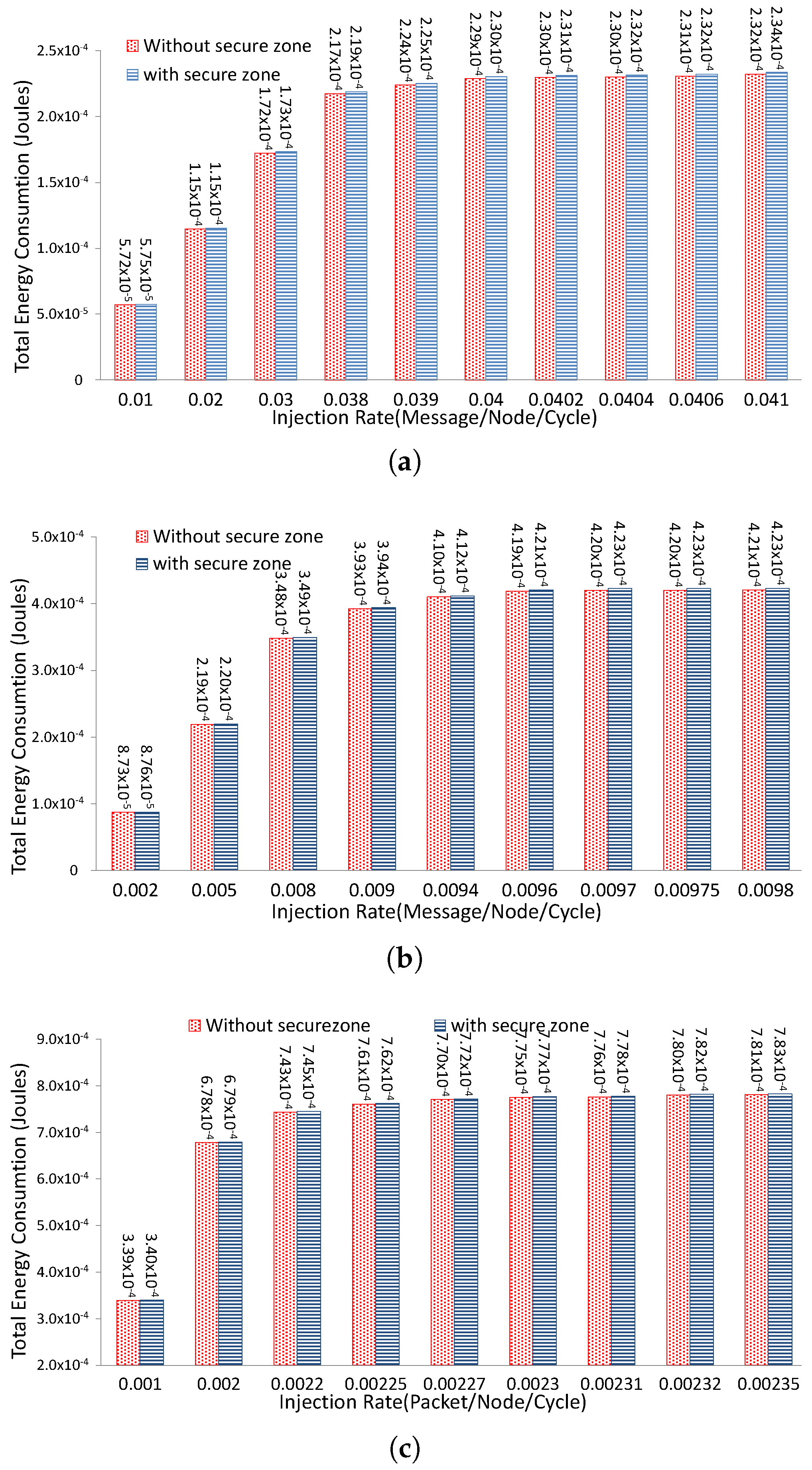
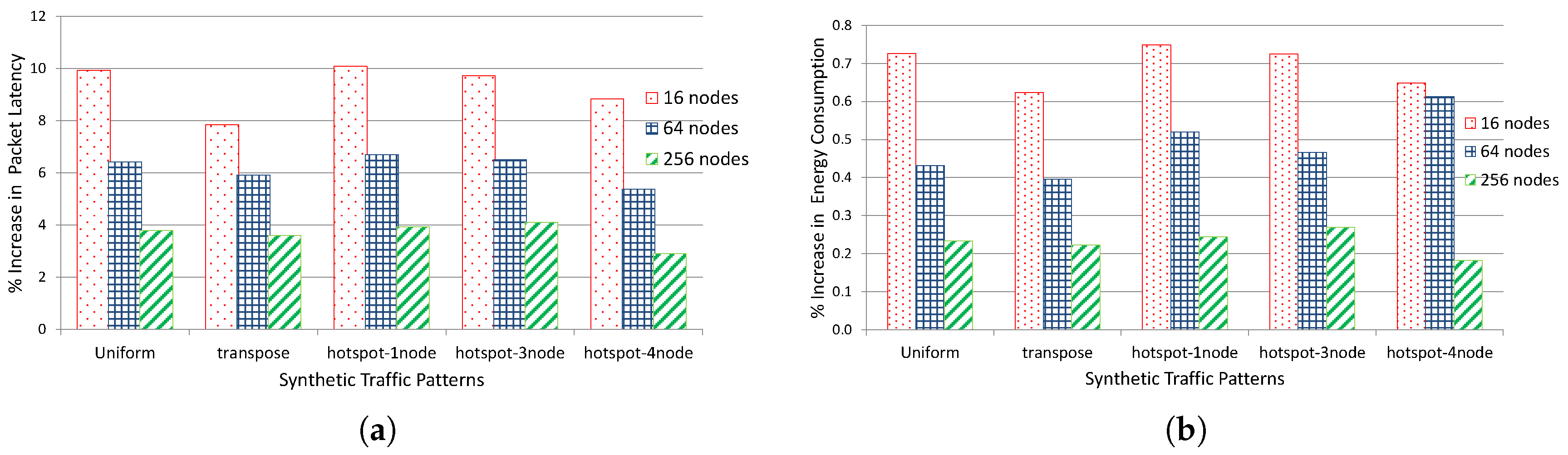
Uniform Traffic Pattern: Under this traffic pattern, packets are uniformly distributed to all the processing cores, which result in high inter-node communication density. The simulation results are presented in Figure 14 and Figure 15. The proposed modifications in the router architecture have negligible impact on the packet latency, where maximum percentage increase of 9.92% is reported for 16 node network as compared to 3.38% increase for the network of 256 nodes. As can be seen in Figure 15 that the proposed security solution has not contributed significantly in the network energy consumption. For instance, as presented in Figure 20b, the secure interface enabled routers have increased network energy consumption by 0.73% for 16 nodes network in the worst case scenario.
Transpose Traffic Pattern: In transpose, as a non-uniform traffic pattern, packets are generated based on a fixed pairing of sources and destinations (a processing core with value communicates with the processing core ). Under such non-uniform traffic patterns, communication between remote cores occurs more frequently and source to destination hop count varies in a non-uniform manner which results in earlier network saturation at a lower packet injection rate when compared to uniform traffic pattern. The detailed simulation results are presented in Figure 16 and Figure 17.
Under transpose traffic pattern our proposed solution has a lower impact on the packet latency and energy consumption as compared to uniform traffic pattern, as will be discussed later in the paper.
Hotspot Traffic Pattern: As realistic applications might generate communication traffic where one or more processing cores accept a greater number of packets as oppose to other processing cores causing hotspot regions. This behavior can be best described synthetically under hotspot traffic pattern where different processing cores are designated as hotspot cores with higher packet injection rate. To evaluate the behavior of our proposed security mechanism under hotspot traffic pattern, a various number of cores are labeled as hotspots and configured to accept double packets as compared to the remaining cores. Hotspots are placed and simulated in three different configurations: one hotspot in the center, three hotspots placed in close proximity and four distributed hotspots with utmost hop-count. For example, the detailed simulation results have been illustrated in Figure 18 and Figure 19 for the four hotspots that are configured in distributed manner and being placed from each other with minimum hop-count of 3, 6 and 14 nodes for the network of 16, 64 and 256 nodes respectively.
As summarized in Figure 20, the proposed security solution has presented approximately comparable or slightly increased overhead both for packet latency and energy consumption under hotspot traffic pattern when compared with the remaining traffic patterns. For example, with four distributed hotspots in 16, 64 and 256 nodes network, the packet latency is increased by 8.83%, 5.38% and 2.91% respectively as compared to 9.72%, 6.51% and 4.10% increase for three closely placed hotspots under similar network settings. Similarly, the network energy consumption overhead for different synthetic patterns is summarized in Figure 20b. These overheads can be reduced further by analysing the communication pattern and the nodes with recurring traffic pattern can be placed in a neighboring area.
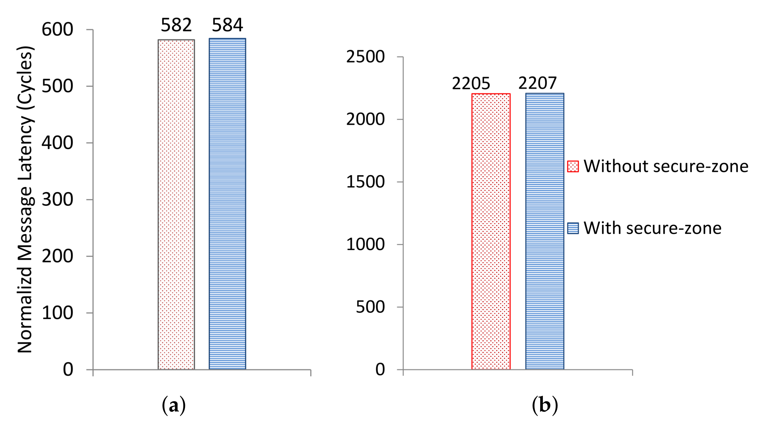
The scalability of the proposed security mechanism is further evaluated by measuring its impact on the performance by simulating multi-threaded applications for a system having 64 cores. For this purpose, the traffic patterns for a number of applications are generated through the Netrace library [38,39]. Netrace is a utility that generates packet traces by simulating a 64-core system executing multi-threaded applications from the PARSEC V2.1 benchmark suite [40]. The traffic patterns for two applications from this benchmark are used in our simulator in a mesh network environment. The impact of embedding secure interface inside each router on average message latency is shown in Figure 21. From these results, it is clearly indicated that the network performance is not much affected when such benchmark applications data is simulated. Moreover, our proposed mechanism has negligible performance overhead when simulated for the benchmark applications as compared to the results generated for the different synthetic traffic patterns.
6. Conclusions and Future Work
In this paper, a practical hardware-based security solution is proposed for a FPGA-based embedded systems and NoC-based communication architecture. The security mechanism has been implemented as a secure zone and it is able to efficiently detect software attacks by identifying unauthorized accesses to the blocks configured within the protected zone. The effectiveness of the proposed mechanism is verified by initiating a buffer-overflow-based software attack which is eventually detected successfully. The feasibility of our solution is illustrated by implementing an authentication system based on a FPGA device with the area and power consumption overheads of 1.23% and 9.5% respectively. Additionally, for NoC-based communication architecture, the secure interface has presented a negligible area and power consumption overhead against a standard router. Moreover, experimental results have been obtained through simulation to present the impact of our approach on the packet latency and total energy consumption for different network sizes and it is shown that the performance and energy overhead is minimal.
Currently, the secure-zone controller module is configured to take input from system user manually. In future work, different ways of autonomous configuration will be investigated and a mechanism will be devised to configure the secure-zone controller remotely over a dedicated secure communication medium.
Author Contributions
A.A. and A.S. conceived the design method and developed the experiments. M.J. provided feedback on fine tuning the concepts and experiment methods. A.S. performed the experiments. All authors analyzed the results. A.A. led the writing with contributions from all authors.
Conflicts of Interest
The authors declare no conflict of interest.
References
- Schaumont, P.; Raghunathan, A. Guest Editors’ Introduction: Security and Trust in Embedded-Systems Design. IEEE Des. Test Comput. 2007, 24, 518–520. [Google Scholar] [CrossRef]
- Ravi, S.; Raghunathan, A.; Kocher, P.; Hattangady, S. Security in embedded systems: Design challenges. ACM Trans. Embed. Comput. Syst. 2004, 3, 461–491. [Google Scholar] [CrossRef]
- Song, D.X.; Wagner, D.; Tian, X. Timing Analysis of Keystrokes and Timing Attacks on SSH. In Proceedings of the USENIX Security Symposium, Washington, DC, USA, 13–17 August 2001; Volume 2001. [Google Scholar]
- Perez, R.; van Doorn, L.; Sailer, R. Virtualization and hardware-based security. IEEE Secur. Priv. 2008, 6, 24–31. [Google Scholar] [CrossRef]
- Suh, G.E.; Lee, J.W.; Zhang, D.; Devadas, S. Secure Program Execution via Dynamic Information Flow Tracking. SIGARCH Comput. Archit. News 2004, 32, 85–96. [Google Scholar] [CrossRef]
- Kornaros, G.; Pnevmatikatos, D. A survey and taxonomy of on-chip monitoring of multicore systems-on-chip. ACM Trans. Des. Autom. Electron. Syst. 2013, 18, 17. [Google Scholar] [CrossRef]
- Arora, D.; Ravi, S.; Raghunathan, A.; Jha, N. Secure embedded processing through hardware-assisted run-time monitoring. In Proceedings of the Design, Automation and Test in Europe, Munich, Germany, 7–11 March 2005; Volume 1, pp. 178–183. [Google Scholar]
- Mao, S.; Wolf, T. Hardware Support for Secure Processing in Embedded Systems. IEEE Trans. Comput. 2010, 59, 847–854. [Google Scholar] [CrossRef]
- Rahmatian, M.; Kooti, H.; Harris, I.; Bozorgzadeh, E. Hardware-Assisted Detection of Malicious Software in Embedded Systems. IEEE Embed. Syst. Lett. 2012, 4, 94–97. [Google Scholar] [CrossRef]
- Yoon, M.K.; Mohan, S.; Choi, J.; Kim, J.E.; Sha, L. SecureCore: A multicore-based intrusion detection architecture for real-time embedded systems. In Proceedings of the 2013 IEEE 19th Real-Time and Embedded Technology and Applications Symposium (RTAS), Philadelphia, PA, USA, 9–11 April 2013; pp. 21–32. [Google Scholar]
- Yan, Q.; Li, Y.; Li, T.; Deng, R. Insights into malware detection and prevention on mobile phones. In Security Technology; Springer: New York, NY, USA, 2009; pp. 242–249. [Google Scholar]
- Rathgeb, C.T.; Peterson, G.D. Secure Processing Using Dynamic Partial Reconfiguration. In Proceedings of the 5th Annual Workshop on Cyber Security and Information Intelligence Research: Cyber Security and Information Intelligence Challenges and Strategies, CSIIRW ’09, Oak Ridge, TN, USA, 13–15 April 2009; p. 58. [Google Scholar]
- Lie, D.; Thekkath, C.; Mitchell, M.; Lincoln, P.; Boneh, D.; Mitchell, J.; Horowitz, M. Architectural Support for Copy and Tamper Resistant Software. SIGPLAN Not. 2000, 35, 168–177. [Google Scholar] [CrossRef]
- Suh, G.E.; Clarke, D.; Gassend, B.; van Dijk, M.; Devadas, S. AEGIS: Architecture for Tamper-evident and Tamper-resistant Processing. In Proceedings of the 17th Annual International Conference on Supercomputing, ICS ’03, San Francisco, CA, USA, 23–26 June 2003; ACM: New York, NY, USA, 2003; pp. 160–171. [Google Scholar]
- Doudalis, I.; Clause, J.; Venkataramani, G.; Prvulovic, M.; Orso, A. Effective and Efficient Memory Protection Using Dynamic Tainting. IEEE Trans. Comput. 2012, 61, 87–100. [Google Scholar] [CrossRef]
- Kemerlis, V.P.; Portokalidis, G.; Jee, K.; Keromytis, A.D. Libdft: Practical Dynamic Data Flow Tracking for Commodity Systems. SIGPLAN Not. 2012, 47, 121–132. [Google Scholar] [CrossRef]
- Trusted Computing Group. TPM Spectfications for Embedded Systems. Available online: http://www.trustedcomputinggroup.org/developers/embedded_systems (accessed on 15 March 2018).
- ARM. TrustZone. Available online: http://arm.com/products/processors/technologies/trustzone (accessed on 15 March 2018).
- Intel. VT-d. Available online: http://software.intel.com/en-us/articles/intel-virtualization-technology-for-directed-io-vt-d (accessed on 15 March 2018).
- Pék, G.; Buttyán, L.; Bencsáth, B. A survey of security issues in hardware virtualization. ACM Comput. Surv. 2013, 45, 40. [Google Scholar] [CrossRef]
- La Polla, M.; Martinelli, F.; Sgandurra, D. A survey on security for mobile devices. IEEE Commun. Surv. Tutor. 2013, 15, 446–471. [Google Scholar] [CrossRef]
- Fiorin, L.; Palermo, G.; Lukovic, S.; Catalano, V.; Silvano, C. Secure Memory Accesses on Networks-on-Chip. IEEE Trans. Comput. 2008, 57, 1216–1229. [Google Scholar] [CrossRef]
- Lukovic, S.; Christianos, N. Enhancing network-on-chip components to support security of processing elements. In Proceedings of the 5th Workshop on Embedded Systems Security, WESS ’10, Scottsdale, AZ, USA, 24 October 2010; p. 12. [Google Scholar]
- Porquet, J.; Greiner, A.; Schwarz, C. NoC-MPU: A secure architecture for flexible co-hosting on shared memory MPSoCs. In Proceedings of the Design, Automation Test in Europe Conference Exhibition (DATE), Grenoble, France, 14–18 March 2011; pp. 1–4. [Google Scholar]
- Wassel, H.M.G.; Gao, Y.; Oberg, J.K.; Huffmire, T.; Kastner, R.; Chong, F.T.; Sherwood, T. SurfNoC: A Low Latency and Provably Non-interfering Approach to Secure Networks-on-chip. In Proceedings of the 40th Annual International Symposium on Computer Architecture, ISCA ’13, Tel-Aviv, Israel, 23–27 June 2013; ACM: New York, NY, USA, 2013; pp. 583–594. [Google Scholar] [CrossRef]
- Wassel, H.; Gao, Y.; Oberg, J.; Huffmire, T.; Kastner, R.; Chong, F.; Sherwood, T. Networks on Chip with Provable Security Properties. IEEE Micro 2014, 34, 57–68. [Google Scholar] [CrossRef]
- Grammatikakis, M.D.; Papadimitriou, K.; Petrakis, P.; Papagrigoriou, A.; Kornaros, G.; Christoforakis, I.; Tomoutzoglou, O.; Tsamis, G.; Coppola, M. Security in MPSoCs: A NoC Firewall and an Evaluation Framework. IEEE Trans. Comput.-Aided Des. Integr. Circuits Syst. 2015, 34, 1344–1357. [Google Scholar] [CrossRef]
- Hu, Y.; Müller-Gritschneder, D.; Sepulveda, M.J.; Gogniat, G.; Schlichtmann, U. Automatic ILP-based Firewall Insertion for Secure Application-Specific Networks-on-Chip. In Proceedings of the 2015 Ninth International Workshop on Interconnection Network Architectures: On-Chip, Multi-Chip (INA-OCMC), Amsterdam, The Netherlands, 19 January 2015; pp. 9–12. [Google Scholar] [CrossRef]
- Saeed, A.; Ahmadinia, A.; Just, M. Secure On-Chip Communication Architecture for Reconfigurable Multi-Core Systems. J. Circuits Syst. Comput. 2016, 25, 1650089. [Google Scholar] [CrossRef]
- Saeed, A.; Ahmadinia, A.; Javed, A.; Larijani, H. Intelligent Intrusion Detection in Low-Power IoTs. ACM Trans. Internet Technol. (TOIT) 2016, 16, 27. [Google Scholar] [CrossRef]
- Saeed, A.; Ahmadinia, A.; Just, M. Hardware-assisted secure communication for FPGA-based embedded systems. In Proceedings of the 2015 11th Conference on Ph.D. Research in Microelectronics and Electronics (PRIME), Glasgow, UK, 29 June–2 July 2015; pp. 216–219. [Google Scholar] [CrossRef]
- Platform Studio and the Embedded Development Kit (EDK). Available online: https://www.xilinx.com/products/design-tools/platform.html (accessed on 15 March 2108).
- Lhee, K.S.; Chapin, S.J. Buffer overflow and format string overflow vulnerabilities. Softw. Pract. Exp. 2003, 33, 423–460. [Google Scholar] [CrossRef]
- Younan, Y. 25 Years of Vulnerabilities: 1988–2012. Available online: http://labs.snort.org/ (accessed on 15 March 2018).
- Xilinx Power Estimator. Available online: http://xilinx.com/products/technology/power/xpe (accessed on 15 March 2108).
- Hu, J.; Marculescu, R. Energy- and performance-aware mapping for regular NoC architectures. IEEE Trans. Comput.-Aided Des. Integr. Circuits Syst. 2005, 24, 551–562. [Google Scholar]
- Wang, H.S.; Zhu, X.; Peh, L.S.; Malik, S. Orion: A power-performance simulator for interconnection networks. In Proceedings of the 35th Annual IEEE/ACM International Symposium on Microarchitecture (MICRO-35), Istanbul, Turkey, 18–22 November 2002; pp. 294–305. [Google Scholar]
- Hestness, J.; Grot, B.; Keckler, S.W. Netrace: Dependency-driven trace-based network-on-chip simulation. In Proceedings of the Third International Workshop on Network on Chip Architectures, Atlanta, GA, USA, 4 December 2010; ACM: New York, NY, USA, 2010; pp. 31–36. [Google Scholar]
- Hestness, J.; Keckler, S.W. Netrace: Dependency-Tracking Traces for Efficient Network-on-Chip Experimentation; Technical Report TR-10-11; The University of Texas at Austin, Department of Computer Science: Austin, TX, USA, 2011. [Google Scholar]
- Bienia, C.; Kumar, S.; Singh, J.P.; Li, K. The PARSEC benchmark suite: Characterization and architectural implications. In Proceedings of the 17th International Conference on Parallel Architectures and Compilation Techniques, Toronto, ON, Canada, 25–29 October 2008; ACM: New York, NY, USA, 2008; pp. 72–81. [Google Scholar]
Figure 1.
Prototype of embedded system enabled with secure zone.

Figure 2.
Block level implementation of secure zone.

Figure 3.
Internal working of secure interface.

Figure 4.
Prototype of image processing-based authentication system enabled with secure zone.

Figure 5.
Secure zone with secure interface.

Figure 6.
Image Processing-based authentication (signature matching) system flowchart.

Figure 7.
Code Execution (a) Without buffer overflow attack; (b) With buffer overflow attack.

Figure 8.
System control flow diagram. (a) Normal control flow without secure interface; (b) Control flow with secure interface.
Figure 8.
System control flow diagram. (a) Normal control flow without secure interface; (b) Control flow with secure interface.

Figure 9.
(a) FPGA slice utilization with and without secure zone; (b) Power Consumption with and without secure zone.
Figure 9.
(a) FPGA slice utilization with and without secure zone; (b) Power Consumption with and without secure zone.

Figure 10.
Performance overhead: Number of cycles required to update image library.

Figure 11.
Secure interface embedded inside local input port of the router.

Figure 12.
Area overhead of security interface on the routers for different network sizes. (a) 4 × 4 mesh network; (b) 8 × 8 mesh network; (c) 16 × 16 mesh network.
Figure 12.
Area overhead of security interface on the routers for different network sizes. (a) 4 × 4 mesh network; (b) 8 × 8 mesh network; (c) 16 × 16 mesh network.

Figure 13.
Power overhead of security interface on the routers for different network sizes; (a) 4 × 4 mesh network; (b) 8 × 8 mesh network; (c) 16 × 16 mesh network.
Figure 13.
Power overhead of security interface on the routers for different network sizes; (a) 4 × 4 mesh network; (b) 8 × 8 mesh network; (c) 16 × 16 mesh network.

Figure 14.
Average packet latency with uniform traffic pattern. (a) 4 × 4 mesh network; (b) 8 × 8 mesh network; (c) 16 × 16 node network.
Figure 14.
Average packet latency with uniform traffic pattern. (a) 4 × 4 mesh network; (b) 8 × 8 mesh network; (c) 16 × 16 node network.

Figure 15.
Network energy consumption with uniform traffic pattern. (a) 4 × 4 mesh network; (b) 8 × 8 mesh network; (c) 16 × 16 mesh network.
Figure 15.
Network energy consumption with uniform traffic pattern. (a) 4 × 4 mesh network; (b) 8 × 8 mesh network; (c) 16 × 16 mesh network.

Figure 16.
Average packet latency with transpose traffic pattern. (a) 4 × 4 mesh network; (b) 8 × 8 mesh network; (c) 16 × 16 node network.
Figure 16.
Average packet latency with transpose traffic pattern. (a) 4 × 4 mesh network; (b) 8 × 8 mesh network; (c) 16 × 16 node network.


Figure 17.
Network energy consumption with transpose traffic pattern. (a) 4 × 4 mesh network; (b) 8 × 8 mesh network; (c) 16 × 16 mesh network.
Figure 17.
Network energy consumption with transpose traffic pattern. (a) 4 × 4 mesh network; (b) 8 × 8 mesh network; (c) 16 × 16 mesh network.


Figure 18.
Average packet latency with four distributed hotspots. (a) 4 × 4 mesh network; (b) 8 × 8 mesh network; (c) 16 × 16 node network.
Figure 18.
Average packet latency with four distributed hotspots. (a) 4 × 4 mesh network; (b) 8 × 8 mesh network; (c) 16 × 16 node network.

Figure 19.
Network energy consumption with four distributed hotspots. (a) 4 × 4 mesh network; (b) 8 × 8 mesh network; (c) 16 × 16 mesh network.
Figure 19.
Network energy consumption with four distributed hotspots. (a) 4 × 4 mesh network; (b) 8 × 8 mesh network; (c) 16 × 16 mesh network.

Figure 20.
Maximum percentage increase in packet latency and total network energy consumption under different synthetic traffic patterns. (a) Percentage increase in packet latency. (b) Percentage increase in total network energy consumption.
Figure 20.
Maximum percentage increase in packet latency and total network energy consumption under different synthetic traffic patterns. (a) Percentage increase in packet latency. (b) Percentage increase in total network energy consumption.

Figure 21.
Message latency for 64 node network using multithreaded applications from PARSEC benchmark suite. (a) blackscholes application; (b) fluidanimate application.
Figure 21.
Message latency for 64 node network using multithreaded applications from PARSEC benchmark suite. (a) blackscholes application; (b) fluidanimate application.

© 2018 by the authors. Licensee MDPI, Basel, Switzerland. This article is an open access article distributed under the terms and conditions of the Creative Commons Attribution (CC BY) license (http://creativecommons.org/licenses/by/4.0/).
Share and Cite
MDPI and ACS Style
Saeed, A.; Ahmadinia, A.; Just, M. Hardware-Assisted Secure Communication in Embedded and Multi-Core Computing Systems. Computers 2018, 7, 31. https://doi.org/10.3390/computers7020031
AMA Style
Saeed A, Ahmadinia A, Just M. Hardware-Assisted Secure Communication in Embedded and Multi-Core Computing Systems. Computers. 2018; 7(2):31. https://doi.org/10.3390/computers7020031
Chicago/Turabian StyleSaeed, Ahmed, Ali Ahmadinia, and Mike Just. 2018. "Hardware-Assisted Secure Communication in Embedded and Multi-Core Computing Systems" Computers 7, no. 2: 31. https://doi.org/10.3390/computers7020031
Note that from the first issue of 2016, this journal uses article numbers instead of page numbers. See further details here.