1. Introduction
The use of liquid fuel in low temperature polymeric electrolyte membrane fuel cells (PEMFC) combines high power density and simplicity for fuel handling. Among them, direct formic acid fuel cells (DFAFC) are interesting because the formic acid crossover in the fuel cell membranes is significantly lower than that for methanol [
1]. Additionally, the use of formic acid allows a high open circuit potential [
2].
The high cost of the most active catalysts implies that the surface/mass ratio should be as high as possible,
i.e., metal nonoparticles (NP) should be spread over an inexpensive and high surface material [
3]. The use of carbon material as support meets these requirements: low cost, acceptable electronic resistance and chemical stability. Additionally, the need for large metal loadings, frequently between 20% and 60% of the whole mass, requires widespread anchorage sites for catalysts nanoparticles, which results in the need for high surface materials [
4]. The most used approach utilizes a carbon support over which the catalytic metal is deposited. However, the employment of nanoparticulated carbon supports also involves ohmic drops due to the interparticle resistance as well as mass transfer obstruction.
Two possible approaches for the mass transport improvement can be considered: short diffusion lengths in thin films, like reported previously for mesoporous metal films, or thicker materials with special pore design for improved diffusion [
5,
6].
Considering the second approach, the use of high surface monolithic carbon may offer some advantage [
2,
7]. The use of a larger piece of carbon, with dimensions on the scale of microns, decreases the ohmic drop originated in the interparticle contact. On the other hand, the use of new synthetic routes allows the surface area to stay high enough, and improves the mass transport by the ad-hoc pore design in hierarchical levels. However, the monolithic nature of the porous support imposes new challenges for metal loading, and the well-known method for metal impregnation should be revised and modified [
2,
6].
One additional consideration about DFAFC emphasizes the need for an improved mass transport. In the anode of DFAFC, the processes for formic acid (FA) oxidation produce CO
2 and two electrons per FA molecule, according to reaction (1):
In comparison, methanol (see reaction (2)) is able to produce until six electrons for each fuel molecule:
Therefore, for DFAFC the mass transport must be high enough to keep the limiting current value at acceptable levels, at least if comparable current densities are desired. Additionally, it has been proposed that severe mass transport limitations are associated to the hydrophilic character of the formic acid [
8]. For these reasons, a careful material design for an efficient mass transport is necessary.
In this work, the use of hierarchical porous carbon (HPC) as support for PtPd nanoparticles is explored. Three hierarchical porous carbon (HPC-300, HPC-400 and HPC-500) samples with main pore size around 300, 400 and 500 nm respectively, are used as porous support. The resulting material is characterized by EDX, XRD and conventional electrochemical techniques. Finally, the catalytic activity toward formic acid and methanol electrooxidation was evaluated. It is concluded that the catalysts show appropriate behavior to be used for anodes in DFAFC and cathodes in DMFC.
2. Results and Discussion
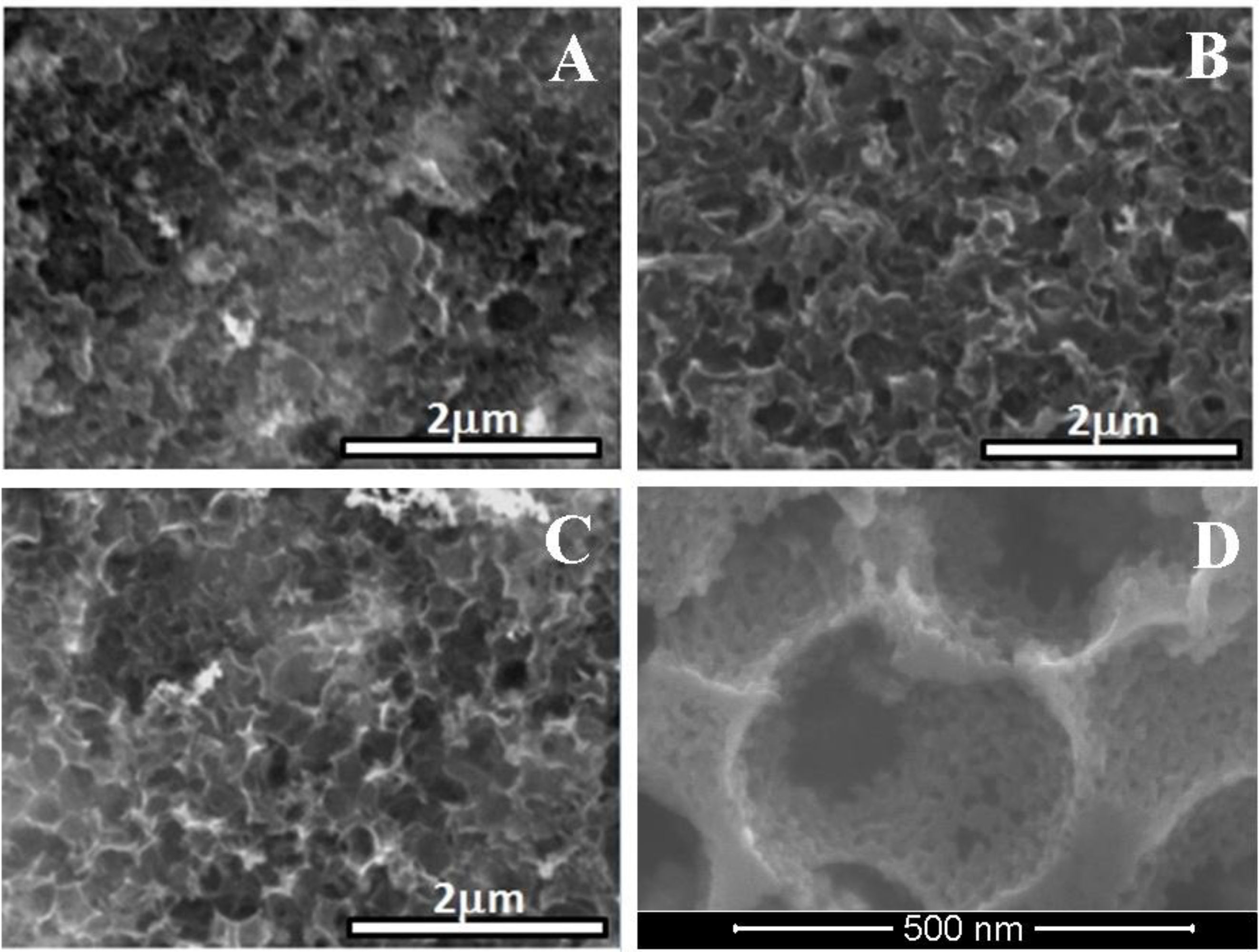
The
Figure 1 shows the SEM images of the PtPd/HPC300 (A), PtPd/HPC400 (B), PtPd/HPC500 (C) and high magnification SEM of HPC400 (D). Due to the fragility of the carbon material, after impregnation, the exterior surface of the carbon support shows signs of fracture and local collapse of the macropores, which is clearly visible in sample A–B, and nearly imperceptible in the sample C. The
Figure 1D shows the second level of porosity, visible at the pore wall. The image was taken inside of one of the microparticles in the HPC400 support. As it was previously reported, this additional porosity in the mesoscale was attributed to the hindered contraction during pyrolysis due the presence of the SiO
2 rigid template.
Figure 1.
SEM images of the PtPd/HPC300 (A); PtPd/HPC400 (B); PtPd/HPC500 (C) and high magnification SEM of HPC400 (D).
Figure 1.
SEM images of the PtPd/HPC300 (A); PtPd/HPC400 (B); PtPd/HPC500 (C) and high magnification SEM of HPC400 (D).
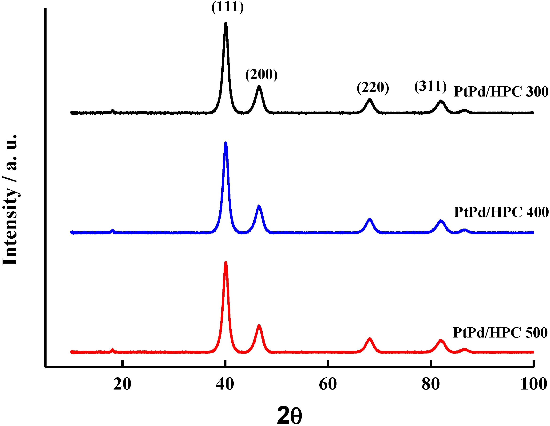
EDS analysis of the impregnated HPC reveals that all samples have a composition of Pt:Pd of approximately 1:1, in good agreement with the feeding composition during synthesis. On the other hand, the metal load shows a broader distribution between 17% and 28% p/p. The diffractograms for all PtPd/HPC catalysts are given in
Figure 2. The crystallite size was estimated by means of the Scherrer equation, obtaining values in the order of 6 nm, a little above the value of a commercial PtPd/C (E-TEK) which is 4.5 nm (see
Table 1).
Figure 2.
XRD diffractograms of PtPd/HPC samples.
Figure 2.
XRD diffractograms of PtPd/HPC samples.
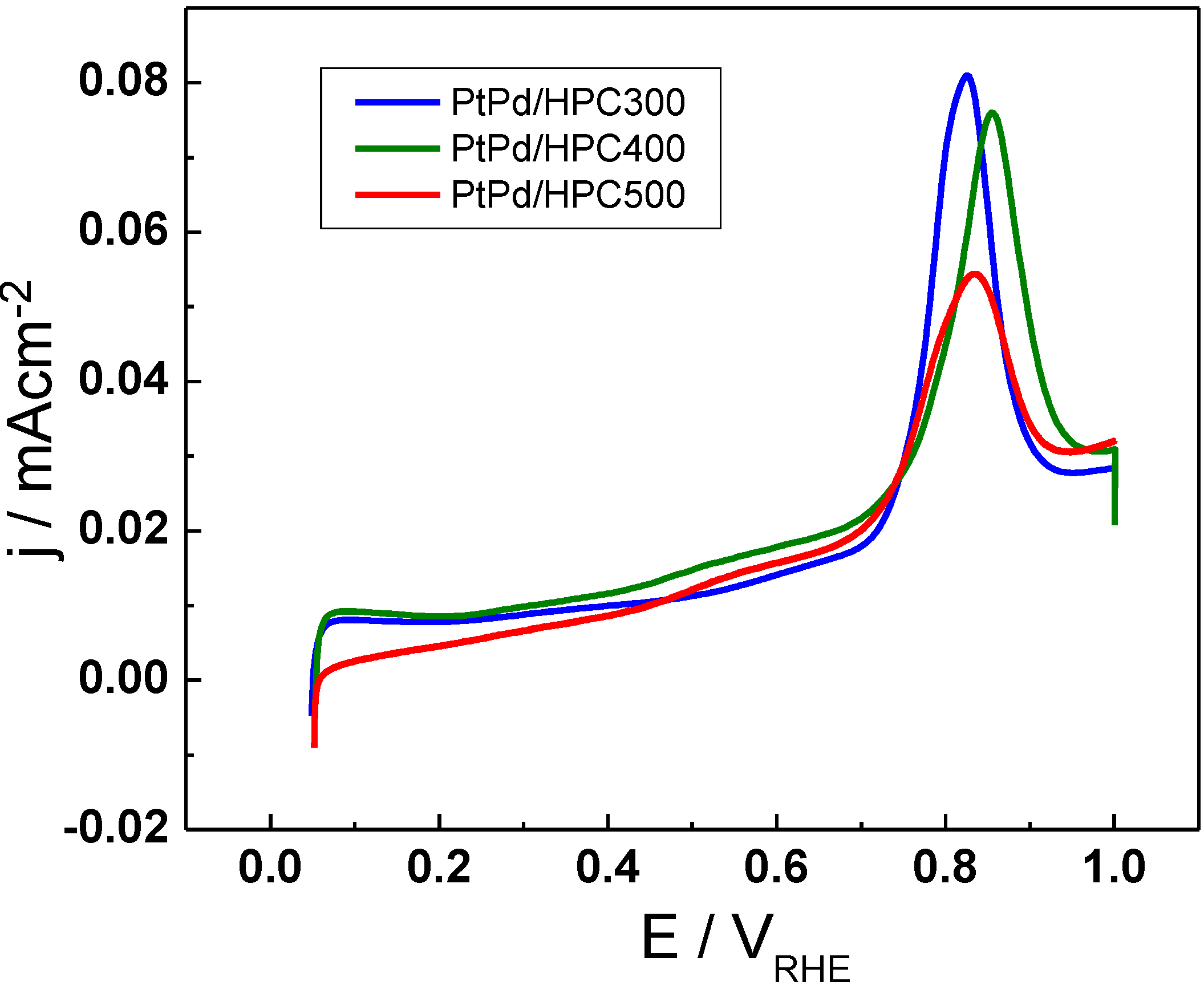
The electrochemical characterization of the catalysts surface includes a CO stripping experiment performed with the purpose of evaluating the extension of the metal surface exposed to the solution (see
Figure 3). With this idea, the charge associated to the CO stripping was calculated and the area was determined assuming 420 μC cm
−2 for a CO adsorbed monolayer. The results show that the electrochemically active surface area (ESA, expressed in terms of m
2 g
−1) for all tree catalysts synthesized in this work is smaller than the commercial catalyst, being of 38.8 m
2 g
−1 for the PtPd/HPC300; 40.2 m
2 g
−1 for the PtPd/HPC400 and 49.6 m
2 g
−1 for the PtPd/HPC500; whereas a value of 62.6 m
2 g
−1 was obtained for PtPd/C E-TEK in the same conditions (
Table 1).
Table 1.
EDS, XRD and ESA results for PtPd/HPCs and commercial PtPd/C E-TEK.
Table 1.
EDS, XRD and ESA results for PtPd/HPCs and commercial PtPd/C E-TEK.
| Catalysts | Atomic composition (%) | Metal composition (%) | Crystallite size (nm) | Lattice parameter | ESA(m2 g−1) |
|---|
| PtPd/HPC500 | 53 Pd | 28.5 | 5.9 | 3.897 | 49.6 |
| 47 Pt |
| PtPd/HPC400 | 52 Pd | 17.0 | 6.0 | 3.904 | 40.2 |
| 48 Pt |
| PtPd/HPC300 | 53 Pd | 17.6 | 5.6 | 3.893 | 38.8 |
| 47 Pt |
| PtPd/C E-TEK | 49 Pd | 20.0 | 4.5 | 3.896 | 62.6 |
| 51 Pt |
These values suggest the absence of a direct relationship between the crystallite size and the surface extension (or electroactive surface area), although the higher surface area is achieved by the catalysts with the lower crystallite size. However, high catalyst area does not necessarily imply increased catalyst activity, as will be proved later. On the other hand, the change in the peak position for CO electrooxidation is not significant when going from one catalyst to the other. It is located at approx. 0.85 V
HRE, near 50 mV and it shifted to more negative potentials when compared with commercial PtPd/C [
9]. This result is reasonable considering that all PtPd/HPC catalysts have the same composition, about 53% Pd and 47% Pt.
Although the catalyst loading process is performed on a very porous material, it is a remarkable fact that it is possible to obtain a supported catalyst composed of relatively small NP which has the same metal composition as the feeding catalyst [
2]. The existence of a relatively well dispersed metal NP probably lies in the second level of porosity inside the pore wall. The mesoporous network contributes to fixing the metal seed to the carbon surface during the impregnation with the precursors. Such “defects” on the porous surface prevent migration and the subsequent agglomeration.
Figure 3.
CO stripping voltammograms for PtPd/HPC300, PtPd/HPC400 and PtPd/HPC500 catalysts in 0.5 M H2SO4, 25 °C, 20 m V s−1.
Figure 3.
CO stripping voltammograms for PtPd/HPC300, PtPd/HPC400 and PtPd/HPC500 catalysts in 0.5 M H2SO4, 25 °C, 20 m V s−1.
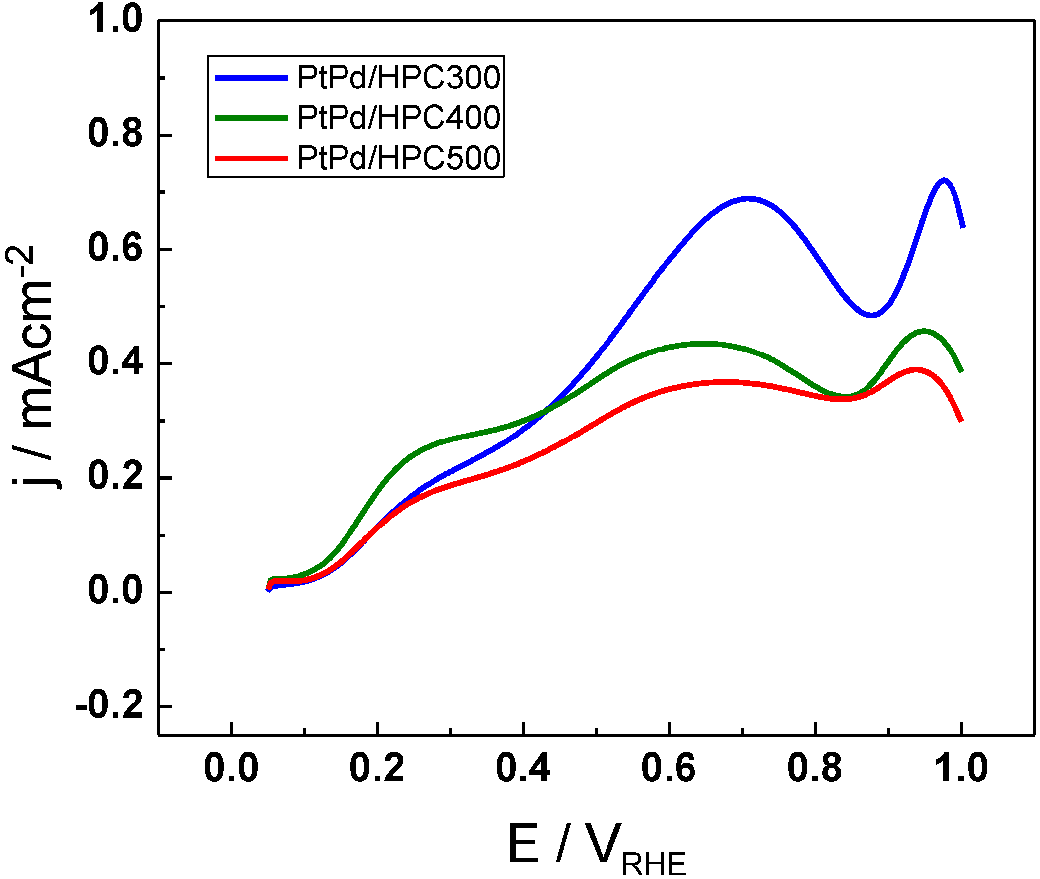
The activity towards formic acid electrooxidation was tested by cyclic voltammetry (CV) (
Figure 4) and chronoamperometry (CA) (
Figure 5). The anodic scan for formic acid electrooxidation at 25 °C in 0.5 M H
2SO
4 is shown in
Figure 4 for the three PtPd/HPC materials. The onset for formic acid oxidation is the same for all PtPd/HPC and it is positioned around 0.1 V
RHE. The current has a similar behavior in the three catalysts, but substantial differences in the maximum current achieved in each of them. The current increases gradually sweeping the potential from the initial value of 0.05 V up to 0.25 V, and then change the rate of increasing or remains constant up to approx. 0.4 V
RHE, describing a shoulder. From this point, there begins a new increase, attaining a peak about 0.65 V
RHE (PtPd/HPC400 and PtPd/HPC500) or 0.70 V
RHE (PtPd/HPC300). These results are in good agreement with the mechanism proposed for formic acid oxidation, suggested during the last century in the middle of the 1970s by Capon and Parsons, which assume a dual pathway [
10]. It has been proposed that, at lower potentials, an active intermediary is present, like adsorbed formate [
11]. The parallel method involves a strong chemisorbed mediator, like CO [
12,
13].
The maximum current density achieved in the anodic scan fluctuates between 380 µA cm
−2 (PtPd/HPC500) and 690 µA cm
−2 (PtPd/HPC300). In the backward scan (not shown) all catalysts display a sharp rising of the current density, usually associated with the surface regeneration after poison removal in the upper scan limit (
i.e., after oxidation of residual adsorbed CO) [
14].
Figure 4.
Cyclic voltammetry (CV) for PtPd/HPC300, PtPd/HPC400 and PtPd/HPC500 catalysts in0.5 M HCOOH + 0.5 M H2SO4, 25 °C, 20 mV s−1.
Figure 4.
Cyclic voltammetry (CV) for PtPd/HPC300, PtPd/HPC400 and PtPd/HPC500 catalysts in0.5 M HCOOH + 0.5 M H2SO4, 25 °C, 20 mV s−1.
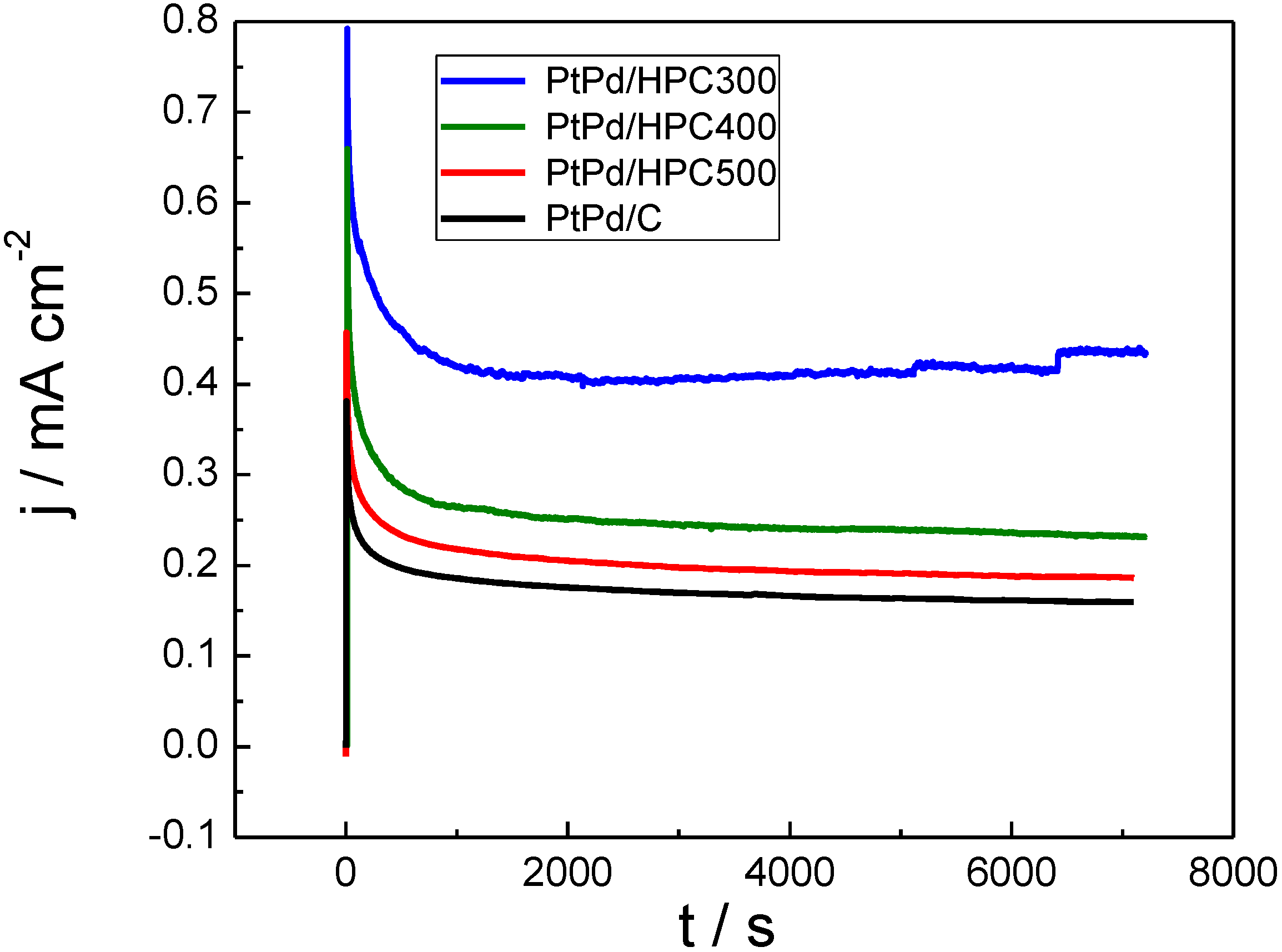
On the other hand, it is reasonable to assume that, under operative fuel cell conditions, the potential in the anode changes only as a response to the current density (load conditions). In stationary regime, both poisoning and mass transfer limitations could seriously affect the observed current density after a few seconds of applying potentiostatic operation conditions. For this reason, chronoamperometric curves were recorded at 0.55 V
RHE (
Figure 5). This potential was chosen because it combines the remaining adsorbed CO not completely removed from the surface (see
Figure 3) and a significant requirement of mass transfer.
Figure 5 shows the current transients after a potential step from 0.05 V
RHE to 0.55 V
RHE in 0.5 M HCOOH + 0.5 M H
2SO
4 at 25 °C for the PtPd/HPC materials (commercial PtPd/C E-TEK was also tested and included as reference). All catalysts display stationary current densities somewhat below that observed in the anodic scan (
Figure 4) at 0.55 V
RHE. Formic acid oxidation generates a copious quantity of CO
2 bubbles (see current steps at the end of the PtPd/HPC300 transient), which could affect the mechanical stability and/or connectivity of some of the HPC films. This fact was a key issue for the PtPd/HPC400 test. For that catalyst, the experience was repeated by changing the substrate due to loss of activity as result of catalyst peeling. Finally, exceptional electrochemical activity (expressed in terms of current densities) toward formic acid oxidation was observed for PtPd/HPC300.
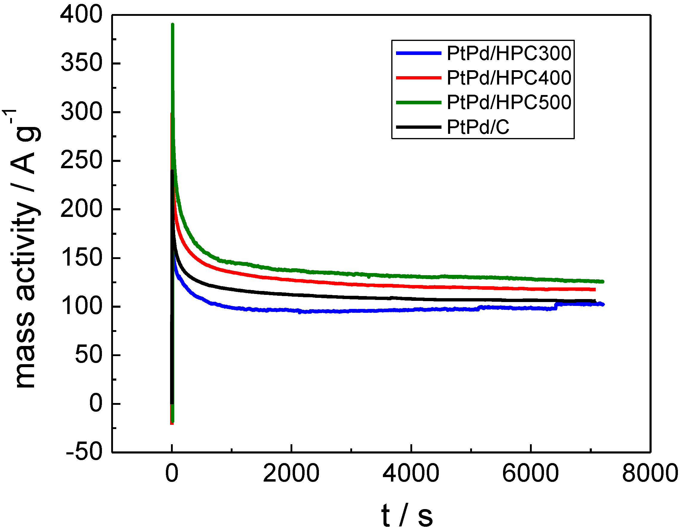
On the other hand, the current can be expressed as mass activity (A g
−1) by considering the PtPd mass for each catalyst (
Figure 6), thus reflecting a quite different fact as these values allow us to establish how much (or how well) the metal catalyst is dispersed in the carbon support. Considering stationary values for mass activity transients, the best performance is achieved by the PtPd/HPC500 (126 A g
−1), then the PtPd/HPC400 (117 A g
−1) followed by the commercial PtPd/C E-TEK, about 106 A g
−1. Comparing PtPd/HPC300 and PtPd/HPC500, the gain in performance can be understood in terms of appropriate balance between exposed surface area and formic acid accessibility to catalytic centers.
Figure 5.
Chronoamperometric curves in terms of current densities for PtPd/HPC300, PtPd/HPC400, PtPd/HPC500 and commercial catalyst recorded at 0.55 VRHE in 0.5 M HCOOH + 0.5 M H2SO4, 25 °C.
Figure 5.
Chronoamperometric curves in terms of current densities for PtPd/HPC300, PtPd/HPC400, PtPd/HPC500 and commercial catalyst recorded at 0.55 VRHE in 0.5 M HCOOH + 0.5 M H2SO4, 25 °C.
Figure 6.
Current transient expressed as mass activity for PtPd/HPC300, PtPd/HPC400, PtPd/HPC500 and commercial catalyst recorded at 0.55 VRHE in 0.5 M HCOOH + 0.5 M H2SO4, 25 °C.
Figure 6.
Current transient expressed as mass activity for PtPd/HPC300, PtPd/HPC400, PtPd/HPC500 and commercial catalyst recorded at 0.55 VRHE in 0.5 M HCOOH + 0.5 M H2SO4, 25 °C.
The lowest surface area catalyst (PtPd/HPC300, see last column in
Table 1) presents the most active surface in terms of current density (
Figure 5), but the worst performance in terms of mass activity (
Figure 6), which can be explained assuming some degree of agglomeration of the NP. In fact, for the same crystallite size, the ESA of the PtPd/HPC300 is only 78% of the area exposed by the PtPd/HPC500. The low surface area of the PtPd/HPC 300 involves a lower fuel requirement flowing through the porous material. In other words, for an equivalent mass transport, more fuel is available for each active site, increasing to some extent the current density. However, the current improvement does not balance the lost in number of active sites due to the poor surface area; for this reason the mass activity is low. On the other hand, the commercial catalyst has the largest ESA of all catalysts tested; however, the mass activity towards HCOOH oxidation is 80% of that delivered by the PtPd/HPC500. Conversely, the PtPd/HPC500 shows high mass activity due to the good dispersion of catalysts nanoparticles inside HPC, but there remains sufficiently high surface activity. The mass activity is somewhat lower than that reported in the literature for Pd catalysts [
15], but it is in the order of other supported PtPd catalysts [
16]. As reported before by several groups, the presence of Pt results in a more stable response of the current [
14,
17].
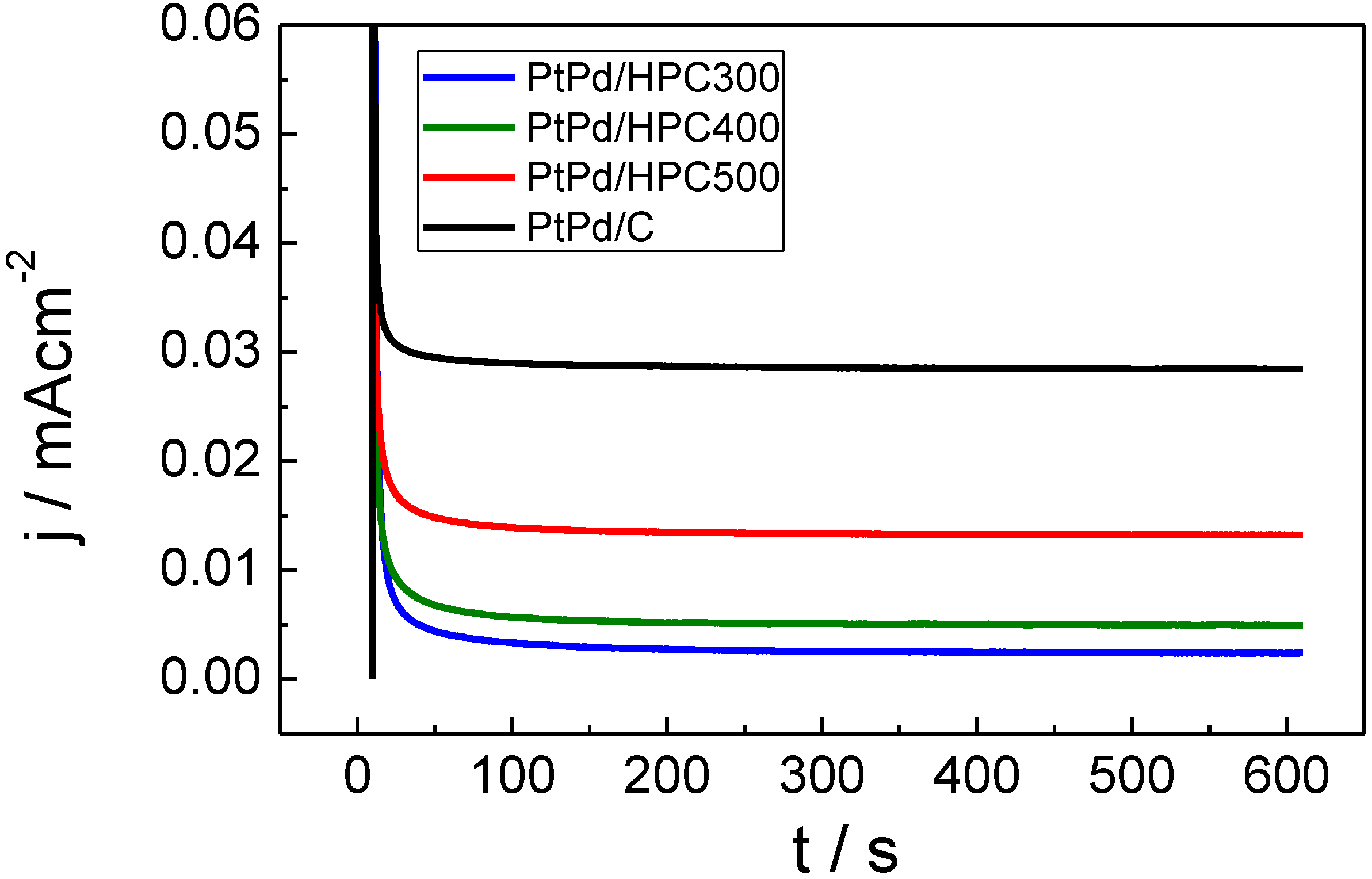
Finally, due to the possibility of the PtPd catalysts to be used in DMFC cathode, the catalysts’ tolerance to methanol was investigated. Chronoamperometric measurements were performed in the presence of 0.5 M CH
3OH at 0.55 V
RHE (
Figure 7). The current transient (mA cm
−2) shows different order when compared with that obtained for the oxidation of formic acid in
Figure 5 (see
Table 2). Both stationary current densities and mass activities increase in the order: PtPd/HPC300 < PtPd/HPC400 < PtPd/HPC500 < PtPd/C E-TEK.
Figure 7.
Chronoamperometric curves in terms of current density for PtPd/HPC300, PtPd/HPC400, PtPd/HPC500 and commercial catalyst recorded at 0.55 VRHE in 0.5 M CH3OH + 0.5 M H2SO4; 25 °C.
Figure 7.
Chronoamperometric curves in terms of current density for PtPd/HPC300, PtPd/HPC400, PtPd/HPC500 and commercial catalyst recorded at 0.55 VRHE in 0.5 M CH3OH + 0.5 M H2SO4; 25 °C.
Again, these responses are surprising because the catalysts’ composition is quite similar and, therefore, similar current densities were expected. When the results are compared in terms of relative mass activity (
Table 2), the best tolerance to methanol (that is, the lowest mass activity) is also obtained with the PtPd/HPC300 catalyst, following the same order than that stated above for the current density.
From these results it is concluded, without any doubt, that the observed selectivity between formic acid and methanol lies in the particle composition, which is similar in all catalysts evaluated. For the same reason, the differences in the electrochemical behavior observed for the PtPd/HPC catalysts synthesized in this work can be attributed to the porous structure of the carbon support.
Table 2.
Electrochemical characterization of the catalysts considering stationary values from current transients. (0.55 VRHE; 25 °C).
Table 2.
Electrochemical characterization of the catalysts considering stationary values from current transients. (0.55 VRHE; 25 °C).
| Catalysts | HCOOH Mass activity (A g−1) | CH3OH Mass activity (A g−1) | HCOOH J (μAcm−2) | CH3OH J (μA cm−2) |
|---|
| PtPd/HPC300 | 106 | 0.5 | 434 | 3 |
| PtPd/HPC400 | 117 | 2.1 | 231 | 5 |
| PtPd/HPC500 | 126 | 9.1 | 186 | 13 |
| PtPd/C E-TEK | 102 | 17.8 | 169 | 28 |
Bigger porous structures influence positively both methanol and formic acid oxidation, mainly due the best catalysts dispersion and increased ESA. On the other hand, the mass transport is yet high enough to further improve the fuel feeding to the catalysts surface. This latter reason explains why the PtPd/HPC500 catalyst is better than the PtPd/C E-TEK, even taking the first a smaller area. Due to the low currents obtained for methanol electrooxidation, the resulting catalytic enhancement is only significant for formic acid oxidation reaction.
3. Experimental Section
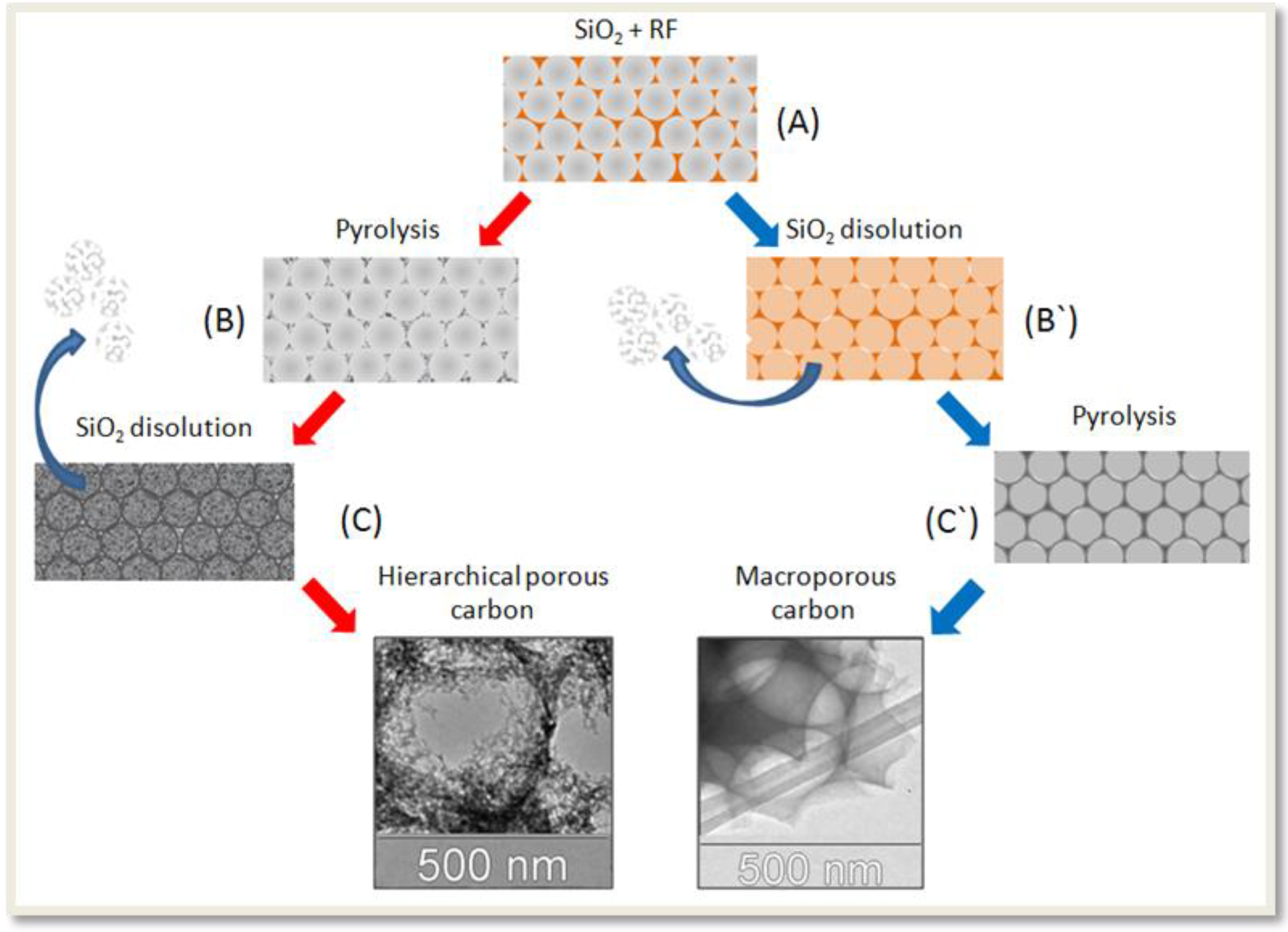
Recently, our group has described the synthesis of mesoporous carbon with hierarchical porous structure (see scheme 1) [
6]. The first step involves the synthesis of SiO
2 NP by TEOS hydrolysis in basic media [
18]. Adjusting the synthesis parameters, it was possible to tune the particle size between 70 and 500 nm. The use of the smallest SiO
2 nanoparticles (dia < 200 nm) produces an extremely fragile carbon material. For this reason, only SiO
2 NP with 300–500 nm diameter were used in this work. Vertical sedimentation of the SiO
2 NP in the bottom of a vial produces a white and rigid solid. After heat treatment at 1000 °C, the monolithic opals were impregnated with the carbon precursor (step “A” in
Scheme 1): a mixture of resorcinol (1 g), formaldehyde (1.6 mL) and sodium carbonate (0.4 mL 0.1 M). The resin-SiO
2 was dried in oven (105 °C) and then pyrolyzed at 850 °C in the absence of O
2 for a 24 h (step “B”). The SiO
2 pattern was then removed by treating the samples with fluorhydric acid solution (step “C”). Note that the way denoted as A→B`→C` produce a macroporous carbon, without additional porosity in the mesoscale level [
6].
The HPC was loaded with PtPd NP using NaBH4. With this purpose, 0.1 g of HPC where suspended in 50 mL of water containing the appropriate quantities of PdCl2 and H2PtCl6. The mixture was stirred by 12 h and the pH was adjusted to 5 by addition of NaOH. After six hours of additional stirring, NaBH4 (50 mg/50 mL of H2O was added drop wise (1 mL/3 min). This dispersion was continually stirred for 24 h more, then filtered and washed.
The diameters of the SiO2 NP were determined by dynamic light scattering (DLS, Malvern 4700 with goniometer and 7132 correlator) with an argon-ion laser operating at 488 nm. All measurements were made at the scattering angle of 90°. Metal content and PtPd atomic ratios of the synthesized catalysts were determined by Energy Dispersive X-Ray Analysis (EDX), using an Oxford Instruments Microanalysis Group 6699 ATW scanning electron microscope at 20 kV, with a Si detector and a Be window. XRD patterns of synthesized catalysts were obtained using an Universal Diffractometer Panalytical X’Pert X-ray, operating with a Cu-Kα radiation generated at 40 kV and 30 mA. Scans were done at 3° min−1 for 2θ values between 20 and 100°. Metal crystallite size and lattice parameters were calculated using the dimensions of peak (220), applying Scherrer’s equation and Vergard’s Law.
Scheme 1.
Steps A–B–C: Synthesis of the mesoporous carbon with hierarchical porous structure (HPC). Steps A-B`-C`: Synthesis of macroporous carbon.
Scheme 1.
Steps A–B–C: Synthesis of the mesoporous carbon with hierarchical porous structure (HPC). Steps A-B`-C`: Synthesis of macroporous carbon.
Electrochemical experiments were carried out in a thermostatized three electrodes electrochemical cell, using a hydrogen reference electrode in the electrolyte solution (RHE) as the reference and a small piece of high surface carbon was used as auxiliary electrode. In this study, the working electrode consists of a certain amount of the PtPd/HPC or commercial PtPd/C E-TEK deposited as a thin layer over a glassy carbon disc (Φ = 3 mm). For this purpose, an aqueous suspension of 4.0 mg mL−1 of the PtPd/HPC or PtPd/C E-TEK catalyst was prepared by ultrasonically dispersing it in 15 µL of Nafion (5 wt.%, Aldrich) and pure water. An aliquot (20 mL) of the dispersed suspension was pipetted on the glassy carbon surface and dried at ambient temperature under Ar atmosphere. The currents are expressed as current densities J (A cm−2), calculated from the measured current I (A) and the real electroactive area S (cm2). S was estimated from CO (N47) stripping experiments. Electrochemical measurements were performed with a PC controlled Autolab PGSTAT30 potentiostat–galvanostat. All reagents were of analytical grade. Argon (N50) was bubbled through the solution to avoid dissolved oxygen. All potentials in this work are given against the RHE.


