Article

La0.6Sr0.4Co0.2Fe0.8O3 Perovskite: A Stable Anode Catalyst for Direct Methane Solid Oxide Fuel Cells

by
Jelvehnaz Mirzababaei
1 and
Steven S. C. Chuang
2,*
1
Department of Chemical and Biomolecular Engineering, The University of Akron, Akron, OH 44325-3909, USA
2
Department of Polymer Science, the University of Akron, Akron, OH 44325-3909, USA
*
Author to whom correspondence should be addressed.
Catalysts 2014, 4(2), 146-161; https://doi.org/10.3390/catal4020146
Submission received: 26 February 2014 / Revised: 23 April 2014 / Accepted: 25 April 2014 / Published: 9 May 2014
(This article belongs to the Special Issue Perovskite Catalysts)

Abstract

:
Direct methane solid oxide fuel cells, operated by supplying methane to a Ni/YSZ anode, suffer from degradation via accumulation of carbon deposits on the Ni surface. Coating a 40 µm thin film of La0.6Sr0.4Co0.2Fe0.8O3 (LSCF) perovskite on the Ni/YSZ anode surface decreased the amount of carbon deposits, slowing down the degradation rate. The improvement in anode durability could be related to the oxidation activity of LSCF which facilitates oxidation of CH4 and carbon deposits. Analysis of the crystalline structure of LSCF revealed that LSCF was stable in the reducing anode environment under H2 and CH4 flow at 750 °C and retained its perovskite structure throughout the 475 h long-term stability test.

Graphical Abstract

1. Introduction

Perovskites are mixed metal oxides with the general formula of ABO3, in which A and B are two different metal cations. Perovskites have attracted vast interest in the catalysis area owing to the unique crystal structure, oxygen vacancy, redox and acid-base properties, and thermal stability. La1−xSrxCo1−yFeyO3 (lanthanum strontium cobalt iron oxide, LSCF) is a perovskite, which has been synthesized by incorporation of strontium and iron cations into a lanthanum cobalt oxide crystal structure.
LSCF has found its application as oxygen membrane [1,2,3,4], catalyst for combustion and oxidative coupling of hydrocarbons [5,6,7], and electrocatalyst for redox reactions in solid oxide fuel cells (SOFCs) [8,9,10,11,12]. LSCF as an electrode for SOFC exhibits high mixed electronic-ionic conductivity, high thermal and chemical stability, and also compatibility with other fuel cell materials. Oxygen permeation fluxes through La1−xSrxCo1−yFeyO3 perovskite have been reported to be comparable or superior to those of YSZ (Y2O3 stabilized ZrO2) membranes at the same temperature [1,2,3,13].
Different methods have been used to prepare LSCF perovskite including Pechini [14,15,16], glycine nitrate combustion [17], solid state reaction [18], and spray pyrolysis [19]. The Pechini method, a solution technique, has been shown to produce high purity and homogeneous perovskite phase with high surface area at low synthesis temperature without intermediate grinding. This approach immobilizes the metal ion precursors in a polyester network which is formed by citric acid and ethylene glycol [20,21]. We employed the Pechini method to synthesize LSCF perovskite for this study.
Fuel cells offer a clean technology with high efficiencies for power generation from direct conversion of chemical energy to electrical energy using fuel and an oxidant. A solid oxide fuel cell consists of an anode and a cathode separated by a solid electrolyte. The anode is in contact with the fuel and the cathode is exposed to air. Figure 1 illustrates the operating principle of solid oxide fuel cell along with the reactions in presence of H2 or CH4 fuel. Oxygen from air adsorbs on the cathode surface becoming oxygen ion and the oxygen ion passes through the ion conducting electrolyte to meet the fuel on the anode side. Electrochemical oxidation of fuel on the anode/electrolyte interface generates products and releases electrons. The transfer of electrons from the anode to the cathode through an external circuit completes the electrochemical cycle [22].
Figure 1. Schematic of solid oxide fuel cell operating principle.
Catalysts 04 00146 g001
Among a wide variety of fuels that can be used in fuel cells, natural gas has generated significant interest because of its abundance in the United States. Therefore, development of a stable anode catalyst for direct utilization of methane as a major component of natural gas has been considered. Nickel in a conventional Ni/YSZ anode shows high catalytic activity for C–H bond dissociation and C–C bond formation in hydrocarbons. Formation of C–C bond, known as coking, deactivates the Ni/YSZ anode catalyst through the loss of active sites and microstructural damage [23,24]. A number of approaches were investigated to suppress the coking and delay the anode deactivation including the addition of steam [25], dilution of hydrocarbon fuel with CO2 [26,27], using the alternate anode materials such as bimetallic anodes [28], and applying a non-coking barrier layer onto the anode surface [29,30].
This study investigated the effect of LSCF perovskite coating on the Ni/YSZ anode surface on long-term stability of the anode in direct CH4 SOFC. LSCF, which has been used frequently as a cathode [31,32,33,34,35], for the first time is used as a promoter in direct CH4 Ni/YSZ anode catalyst. LSCF was selected because of its oxidation activity and mixed conductivity as well as its moderate cost. The cost of LSCF powder is about three times greater than that of conventional Ni/YSZ anode powder.
Although perovskite materials with mixed electronic-ionic conductivity are widely used as cathodes for solid oxide fuel cells, the catalytic and electrocatalytic oxidation activity of perovskites enable the reversible oxygen redox reaction Equation (1) to occur on anodes at the operating temperature of SOFC.
O2 + 4e ↔ 2O2−
The occurrence of Equation (1) in reverse direction for oxidation of CH4 and carbon deposits could be one of the key reasons for LSCF to slow down anode degradation. Activity and long-term stability of a Ni/YSZ anode and a Ni/YSZ anode promoted with LSCF (LSCF-Ni/YSZ) was studied in CH4 by continuous monitoring of electrochemical performances.

2. Results and Discussion

Figure 2 shows voltage-current (V-I) curves and Nyquist plots of impedance spectra for the Ni/YSZ anode fuel cell recorded in He/H2 (100 sccm, 50 vol% H2) after 18 h of reduction and in He/CH4 (25 vol% CH4) after 1 h of switching fuels. The Ni/YSZ anode fuel cell generated a maximum current density of 295 mA/cm2 in H2 and CH4. The relatively low current density of the fuel cell resulted from high resistance of the thick anode and electrolyte layers. Fuel cell resistance is a function of the thickness of the anode, electrolyte and cathode [36]. The ohmic resistances (the intercept of the high frequency impedance arc with the X-axis) of the Ni/YSZ anode in H2 and CH4 are the same. Ohmic resistance resulted from resistance against ion transfer through electrolyte and electrodes, and electron transfer through electrodes and current collectors. Polarization resistances were obtained by subtraction of ohmic contribution from total resistance (the X value at the lowest frequency of impedance arc). The polarization resistances were 7.2 and 6.1 Ω∙cm2 in H2 and CH4, respectively. The absolute value of cathode polarization was assumed to remain constant. Therefore, the change in polarization resistance was ascribed to the change in anode polarization after switching fuels. The change in anode polarization was shown by the ratio of polarization resistance toward oxidation of CH4 to that of H2, which is 0.8 in the current study, compared to 2.5 in our previous work [37]. Values reported for polarization resistance ratios of CH4 to H2 vary from 1.8 to 13.6 depending on operating conditions and fuel cell specifications [38,39,40]. The greater polarization resistance of the Ni/YSZ anode fuel cell in H2 is consistent with the sharper slope of the corresponding V–I curve at low current densities, where voltage loss is dominated by activation polarization [41]. Lower polarization resistance in CH4 than H2 could be related to carbon formation from CH4 dissociation Equation (2).
CH4(g) → Cad + 4Had
Small amounts of carbon deposits may connect some isolated Ni particles, converting them to active sites for electrochemical reactions and allowing the produced electron to transport to the external circuit [42].
Figure 2. V–I curves and Nyquist plots of impedance spectra for the Ni/YSZ anode fuel cell tested at 750 °C in He/H2 (100 sccm, 50 vol% H2) and He/CH4 (100 sccm, 25 vol% CH4). Impedance spectra were recorded at open circuit voltage (OCV) with frequency range of 106–0.05 Hz. t0 is the time at which He/H2 was switched to He/CH4. YSZ = Y2O3 stabilized ZrO2.
Catalysts 04 00146 g002
Figure 3 shows V–I curves and Nyquist plots of impedance spectra for the LSCF-Ni/YSZ anode fuel cell in He/H2 (100 sccm, 50 vol% H2) after 16 h of reduction and in He/CH4 (25 vol% CH4) after 3 h of switching fuels. Fuel cell operation in H2 and CH4 fuel generated a maximum current density of 340 and 355 mA/cm2, respectively. The ohmic resistance in CH4 is lower than that in H2. This could be due to the gradual penetration of Ag, which has been used for current collection, into the cathode microstructure leading to an increase in electronic conductivity [43]. The cross-sectional EDX mapping indicated the presence of Ag across the cathode (result not shown). Polarization resistance of the LSCF-Ni/YSZ anode fuel cell in H2 was 3 Ω∙cm2, which is greater than the 2.3 Ω∙cm2 in CH4. The greater polarization resistance in H2 was also observed for the Ni/YSZ anode fuel cell.
Figure 3. V–I curves and Nyquist plots of impedance spectra for the LSCF-Ni/YSZ anode fuel cell tested at 750 °C in He/H2 (100 sccm, 50 vol% H2) and He/CH4 (100 sccm, 25 vol% CH4). Impedance spectra were recorded at OCV with frequency range of 106–0.1 Hz. t0 is the time at which He/H2 was switched to He/CH4. LSCF = La0.6Sr0.4Co0.2Fe0.8O3.
Catalysts 04 00146 g003
Figure 4 shows maximum power density of the Ni/YSZ and LSCF-Ni/YSZ anode fuel cells recorded during the long-term stability test in CH4. Maximum power density decreased with respect to time for both fuel cells. The rate of decrease in maximum power density is much slower for the LSCF-Ni/YSZ anode than the Ni/YSZ anode fuel cell. The addition of LSCF coating on the Ni/YSZ anode increased the operation life of the direct CH4 fuel cell to 475 h. Maximum power density profile of the LSCF-Ni/YSZ anode exhibits fluctuation with respect to time. This fluctuation could be attributed to repetitive accumulation and oxidation of carbon deposits, in which oxidation of carbon deposits was catalyzed by LSCF perovskite.
Figure 4. Maximum power density of the Ni/YSZ and LSCF-Ni/YSZ anode fuel cell during long-term stability test at 750 °C in He/CH4 (100 sccm, 25 vol% CH4).
Catalysts 04 00146 g004
Figure 5 compares V–I curves and Nyquist plots of impedance spectra of the Ni/YSZ and LSCF-Ni/YSZ anode fuel cells during the long-term stability test in CH4. A relatively rapid decrease was observed in voltage and current density of the Ni/YSZ anode fuel cell over 38 h of operation in CH4. Maximum power density decreased to 22% of its initial value after 38 h. The slopes of the V–I curves at low current densities were decreased after 9 h of operation in CH4, matching with the lower polarization resistances in the corresponding impedance spectra. The decrease in polarization resistance can be explained by deposition of moderate levels of carbon on the anode, which may connect isolated metal particles and convert them to active sites for electrochemical reactions [42]. A gradual decrease in open circuit voltage (OCV) from theoretical OCV was observed after 2 h. A significant decrease in OCV (from 0.8 to 0.6 V) was accompanied by a decrease in current density, indicating initiation of a crack in the fuel cell after about 13 h. Oxygen leakage into the anode chamber from the crack would cause a decrease in OCV and a significant increase in ohmic resistance of the fuel cell, shown in the corresponding impedance spectra in Figure 5a. The cell cracking increased ohmic resistance by weakening contacts between electrodes and current collectors and interrupting the current collection pathway [39]. Further exposure to CH4 fuel resulted in cell fracture and termination of current generation at t0 + 41 h.
Deviation of OCVs from theoretical values, shown in V-I curves of Figure 5b is associated with the leak in the LSCF-Ni/YSZ fuel cell. The OCV gradually decreased from 0.88 to 0.78 V over 440 h due to extension of leakage. The first sign of crack initiation in the LSCF-Ni/YSZ anode appeared by an OCV decrease from 0.78 to 0.4 V after 440 h of exposure to CH4 fuel, compared to 15 h of the Ni/YSZ anode. Current density gradually decreased to 33% of its initial value over 475 h of operation in CH4. Impedance spectra of the LSCF-Ni/YSZ fuel cell recorded at OCV during the long-term stability test did not show a significant increase or decrease, which is indicative of a stable anode that did not undergo severe carbon deposition and structural changes. Noises in impedance spectra that appeared after 440 h operation are likely due to partial detachment of the current collectors from the electrode surfaces.
Figure 5. V–I curves and Nyquist plots of impedance spectra for the (a) Ni/YSZ anode, and (b) LSCF-Ni/YSZ anode fuel cells recorded during the long-term stability test at 750 °C in He/CH4 (100 sccm, 25 vol% CH4). t0 is the time at which He/H2 was switched to He/CH4.
Catalysts 04 00146 g005
Fracture of fuel cells by deposition and diffusion of high levels of carbon into the bulk of the Ni has long been recognized as a key problem of direct methane fuel cells with Ni-based anodes [39,44,45,46]. Examination of the scanning electron microscopy (SEM) image and EDX mapping of the fractured Ni/YSZ anode in Figure 6 revealed that the amount of carbon deposit varied from a C/Ni weight ratio of 0.1 at 5 mm from the center Figure 6a to 0.4 near the center Figure 6b and 0.2 at the center Figure 6c, where the inlet CH4 fuel was directed toward the anode. Figure 6b also shows that the majority of deposited carbon is located on the Ni surface. Previous studies on types of carbon produced on anodes during exposure to hydrocarbon fuels at temperature range of 625–900 °C showed that carbon was deposited in graphitic and disordered form [37,47,48,49]. Graphitic carbon has been suggested to be responsible for anode degradation by dissolution into the bulk of the Ni/YSZ cermet resulting in volume expansion and breakage of the Ni-Ni network [37,50].
Figure 6. The Ni/YSZ anode fuel cell image and scanning electron microscopy (SEM) micrograph/ EDX mapping of the (a) Ni/YSZ surface; (b) coke that is deposited on the Ni/YSZ surface; and (c) coked spot on the Ni/YSZ surface after stability test in CH4.
Catalysts 04 00146 g006
The most obvious effect of LSCF is to delay cracking of the fuel cell from 38 h to 475 h where significant drops in OCV occurred. The SEM image and EDX mapping of the cracked LSCF-Ni/YSZ anode in Figure 7 revealed that deposited carbon was sparse on the Ni particle surface with a C/Ni weight ratio of 0.1, whereas deposited carbon was not observed on LSCF. The absence of carbon deposits on LSCF could be explained by the scheme of the LSCF-Ni/YSZ anode cross-section in Figure 8. This scheme shows that LSCF, a mixed conductor, catalyzes electrocatalytic oxidation of carbon or CH4 with O2 anions transported from YSZ and releases electrons produced during reaction to the Ni connected particles. Distribution of LSCF in the LSCF-Ni/YSZ anode and its effect on fuel cell stability and performance will be further studied.
The ability of LSCF to oxidize carbon should slow down degradation of the Ni/YSZ anode. Oxidation of the deposited carbon from CH4 by LSCF has been viewed as a self de-coking process by Huang et al. [51,52] who suggested that the lattice oxygen of LSCF was responsible for the oxidation. Oxidation by LSCF would produce oxygen vacancies in the LSCF lattice, which may be filled with O2 anions coming from YSZ in the anode. These oxygen extraction (i.e., LSCF reduction) and refilling (i.e., LSCF re-oxidation) processes are kinetic controlled and could lead to oscillation of electric current and CO/CO2 product formation [51]. The formation rate of CO/CO2 oxidation products strongly depends on oxidation activity of the perovskite catalyst. Oxidation activity of perovskites has been related to their reducibility. Highly reducible perovskites such as LaCoO3 have been shown to be more active than less reducible perovskites such as LaCrO3 [13,53]. LaCoO3 has been found to be one of the most stable structures among the Co-based perovskites in reducing environments [54]. LaCoO3 also showed high propensity toward re-oxidization of its reduced forms back to its initial structure [55]. Incorporation of strontium into LaCoO3 could enhance its reducibility, leading to high oxidation activity [56,57,58]. Partial substitution of La3+ with Sr2+, a lower oxidation state cation, would convert Co3+ to Co4+ and produce oxygen vacancies at low O2 partial pressure. This partial substitution could decrease the perovskite stability in a reducing environment [59], but increase the oxygen transport capability and oxidation catalytic activity. Oxidation catalytic activities of the most active perovskites, La1−xSrxBO3 (B: Mn, Co, Fe; 0 < x < 0.4), toward CH4 oxidation are comparable to that of Pt/Al2O3 catalyst [60]. It has also been found that LSCF was able to exhibit high catalytic activity toward CH4 coupling reaction; however, it can exhibit electrocatalytic activity only for complete oxidation of CH4 [61].
Figure 7. Image of the LSCF-Ni/YSZ anode on the cut-off piece of the metal tube reactor after stability test in CH4, and SEM micrograph/ EDX mapping of the (a) Ni/YSZ surface; (b) cracked region on the Ni/YSZ surface; and (c) LSCF surface. The location of carbon is highlighted with red circles.
Catalysts 04 00146 g007
Figure 8. Schematic of the LSCF-Ni/YSZ anode cross-section with LSCF mixed conductor, Ni electronic conductor and YSZ ionic conductor phases.
Catalysts 04 00146 g008
Comparison of XRD patterns of LSCF perovskite before and after the long-term stability test in Figure 9a,b showed that both X-ray diffractometer (XRD) patterns of LSCF matched well with the characteristic peaks of LSCF perovskite phase [62]. It is unclear whether LSCF had decomposed to separate phases and then re-oxidized with O2 anions coming from the cathode side during the stability test or whether it was re-oxidized by exposure to ambient environment. Figure 9b also shows Ni, NiO and YSZ crystalline phases from the LSCF-Ni/YSZ anode along with a number of minor peaks that could not be matched with any known phases.
Figure 9. X-ray diffractometer (XRD) patterns of the (a) synthesized LSCF powder after calcination; and (b) LSCF-Ni/YSZ anode after stability test in CH4.
Catalysts 04 00146 g009
Crystallite size of LSCF and YSZ was increased after the long-term stability test from 16 to 25 nm and from 38 to 46 nm, respectively, as determined by the Scherrer equation. Increase in crystallite size of LSCF on the Ni/YSZ anode due to sintering of perovskite crystallites suggests possible occurrence of a decomposition/re-oxidation process for LSCF. Co- and Fe-based perovskites can be decomposed to separate metal and metal oxide phases in reducing atmospheres [55,63,64]. Re-oxidation of separate metal/metal oxide phases has been observed to reproduce perovskites with large crystallite size [65]. Sintering of particles would decrease catalytic activity by lowering the number of surface sites. Sintering was inhibited by re-oxidation of reduced perovskites at low oxidation rates with very dilute oxygen flow [66,67].
The stability of perovskites including LSCF, especially retaining initial catalytic/electrocatalytic activity and electronic-ionic conductivity, during long-term operation in CH4 has to be considered for the use of these materials as a part of the SOFC anode. Further development will require optimization of electrocatalytic oxidation activity and sintering resistance through fine-tuning perovskite compositions (i.e., adjusting the amounts of dopants to A and B metal cations) and/or searching for proper operating conditions. Studies on stability of LSCF in reducing environments of CH4 and CO2 showed that presence of O2 in the feed gas allowed LSCF to maintain its perovskite structure with the desired electronic-ionic conductivity [68,69]. Perovskites were found to demonstrate reversible redox behavior at temperatures below the sintering temperature of their decomposed phases [13,55,65]. Thus, periodic addition of low concentration of air into CH4 fuel as well as a systematic study of operating temperature could be the options to further stabilize the perovskite on the anode.

3. Experimental Section

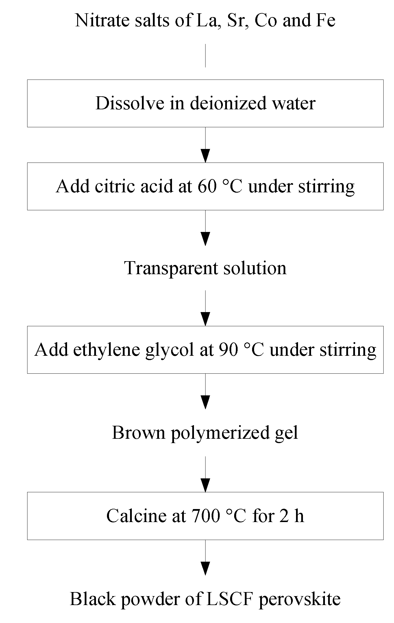
3.1. Synthesis of LSCF Perovskite

La0.6Sr0.4Co0.2Fe0.8O3 perovskite was prepared by the Pechini method [14,15,16] as shown in Figure 10. Metal nitrates of La, Sr, Co and Fe (La(NO3)3·6H2O, Sr(NO3)2, Co(NO3)2·6H2O and Fe(NO3)3·9H2O; Alfa Aesar, Ward Hill, MA, USA) with molar ratio of 3:2:1:4 were dissolved in deionized water at room temperature. Citric acid (BDH) with C/M ratio (i.e., molar percentage of citric acid to all metal cations) of 1.5 and ethylene glycol (Sigma-Aldrich, St. Louis, MO, USA) were added to the aqueous solution under heating and stirring to bind metal cations and form a brownish gel. The produced gel was calcined at 700 °C for 2 h with heating rate of 5 °C/min. The synthesized LSCF powder was characterized using X-ray diffractometer (XRD, PW1710 Philips, PANalytical, Westborough, MA, USA) with Cu-Kα radiation at 35 mA and 40 kV with step size of 0.02° and scanning rate of 1 sec per step. LSCF paste was prepared by mixing the LSCF powder with V-006A vehicle (Heraeus, West Conshohocken, PA, USA).
Figure 10. Flow chart of the Pechini method for synthesis of LSCF perovskite.
Catalysts 04 00146 g010

3.2. Fuel Cell Fabrication

Anode supported fuel cells were prepared by co-tape casting of anode support, anode interlayer and electrolyte slips, and screen-printing of cathode interlayer and cathode current collector layer. The slips of NiO/8YSZ (8 mol% Y2O3 stabilized ZrO2, Tosoh, Tokyo, Japan) 65:35 wt% anode support, NiO/8YSZ 63:37 wt% anode interlayer, and 8YSZ electrolyte were produced by dispersing metal oxide powders in ethanol solvent, introducing binder and dispersant, and ball milling the resulted mixture for 24 h. The anode support slip also contained microcrystalline cellulose pore former (10 wt% PH-301, FMC BioPolymer, Philadelphia, PA, USA). The co-casted tapes were dried in ambient air for 48 h and the dried tapes were cut into 23 mm diameter discs, followed by firing at 1400 °C. LSM (La0.8Sr0.2MnO3)/8YSZ 70:30 wt% (CL86-8706B Heraeus, West Conshohocken, PA, USA) cathode interlayer and LSM (CL86-8706 Heraeus, West Conshohocken, PA, USA) cathode current collector layer were screen-printed on the electrolyte surface with cathode area of 1.95 cm2 and sintered at 1250 and 1100 °C, respectively. The thickness of layers for fabricated fuel cells, determined from cross-sectional SEM micrograph (result not shown), was 1600 µm for anode support, 30 µm for anode interlayer, 25 µm for electrolyte, 40 µm for cathode interlayer, and 20 µm for cathode current collector layer. The LSCF promoted Ni/YSZ anode fuel cell was prepared by reducing Ni/YSZ anode fuel cell in He/H2 (100 sccm, 50 vol% H2) at 750 °C for 16 h. Screen-printing was selected as a convenient technique to coat LSCF on the surface of anode support. Two 40 µm thick strips of LSCF with areas of 0.75 cm2 were screen-printed on the Ni/YSZ surface leaving an uncoated Ni/YSZ surface in between, followed by firing at 1050 °C for 1 h. This fuel cell is labeled as LSCF-Ni/YSZ anode fuel cell versus unmodified fuel cell which is labeled as Ni/YSZ anode fuel cell.

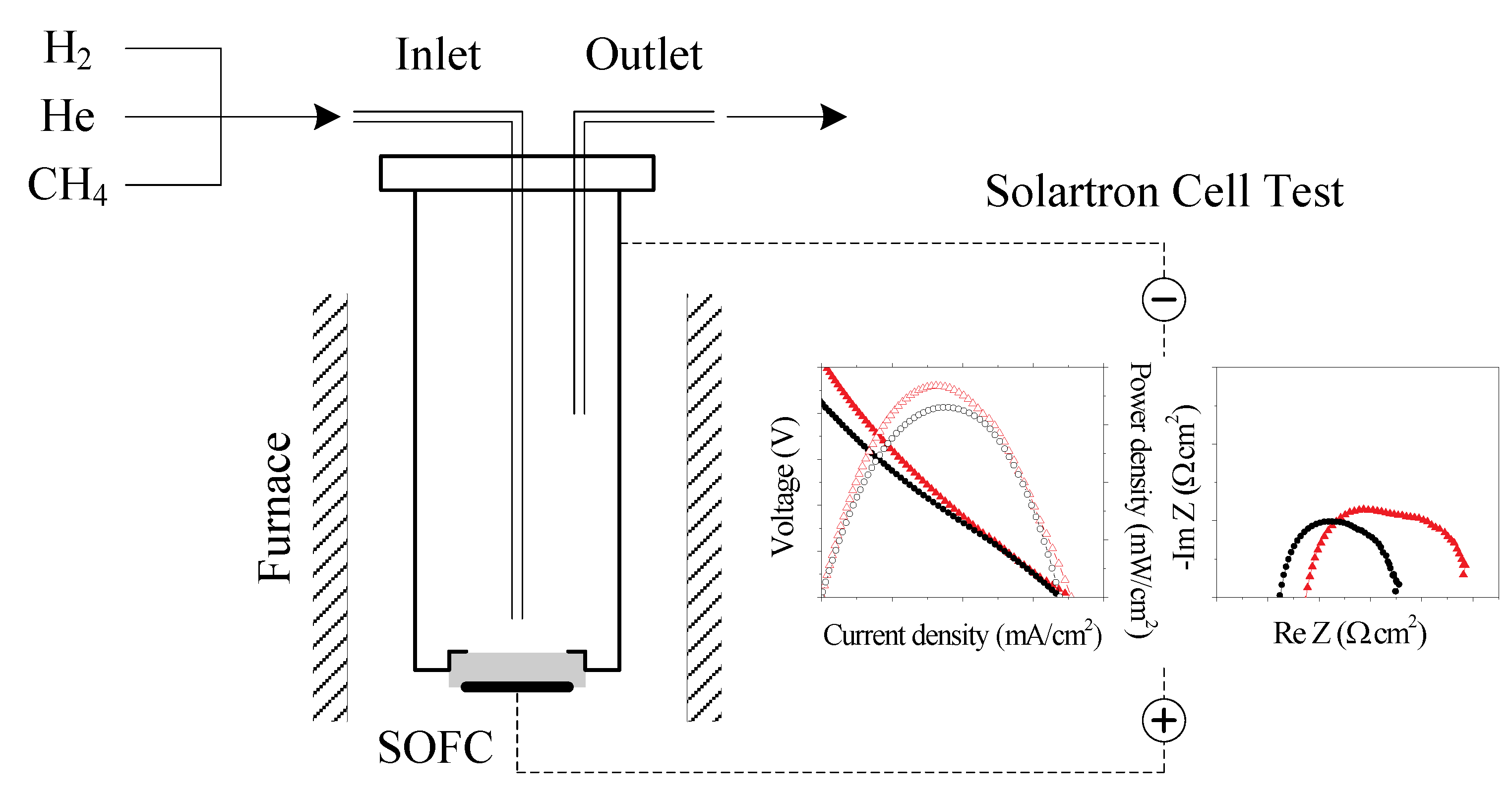
3.3. Fuel Cell Testing and Characterization

An anode supported fuel cell was placed and sealed on a metal tube serving as the anode chamber and anode current collector as illustrated in Figure 11. A silver strip cathode current collector was attached to the cathode surface. A thin layer of silver paste (C8728 Heraeus, West Conshohocken, PA, USA) was applied between the electrodes and current collectors to improve current collection. The fuel cell was heated to 750 °C and reduced in a flow of He/H2 (100 sccm, 50 vol% H2). The flow was then switched to He/CH4 (100 sccm, 25 vol% CH4) for the long-term stability test at 750 °C. The Ni/YSZ and LSCF-Ni/YSZ anode fuel cells were operating under low current densities of 25–50 mA/cm2 throughout the long-term stability test. Voltage-current curves and impedance spectra were recorded at different time intervals with a potentiostat and a frequency response analyzer (1470E and 1400 Solartron CellTest System, Solartron Analytical, Oak Ridge, TN, USA). Composition and microstructure of the tested fuel cells were analyzed using scanning electron microscopy (SEM, TM-3000 Hitachi, Tokyo, Japan) and energy-dispersive X-ray (EDX, Bruker, Ewing, NJ, USA). The LSCF-Ni/YSZ anode was characterized with XRD crystallography after the stability test in CH4.
Figure 11. Solid oxide fuel cell (SOFC) testing apparatus.
Catalysts 04 00146 g011

4. Conclusions

The effect of LSCF perovskite coating on the durability of the conventional Ni/YSZ anode was studied by performing the long-term stability test of the Ni/YSZ and LSCF-Ni/YSZ anode in direct CH4 utilization. Severe carbon deposition resulted in degradation and fracture of the Ni/YSZ anode after 38 h of exposure to CH4. The LSCF-Ni/YSZ anode on the other hand exhibited high stability leading to long-term operation of 475 h in CH4. Compositional and microstructural analysis of the fuel cell anodes after the test indicated lower carbon deposition on the LSCF-Ni/YSZ anode compared to that of Ni/YSZ. LSCF retained its perovskite structure after the long-term stability test in CH4. The results of this study suggest that LSCF is a promising promoter catalyst for stable direct CH4 fuel cell anodes.

Acknowledgments

This work was supported by the Department of Energy (DE-FC36 06GO86055), Ohio Coal Development Office, and FirstEnergy Corporation.

Author Contributions

This work will be a part of dissertation of Jelvehnaz Mirzababaei who carried out the experimental studies under supervision of Steven Chuang who provided the concept and guidance.

Conflicts of Interest

The authors declare no conflict of interest.

References

  1. Teraoka, Y.; Zhang, H.M.; Okamoto, K.; Yamazoe, N. Mixed ionic-electronic conductivity of La1−xSrxCo1−yFeyO3−δ perovskite-type oxides. Mater. Res. Bull. 1988, 23, 51–58. [Google Scholar] [CrossRef]
  2. Teraoka, Y.; Nobunaga, T.; Okamoto, K.; Miura, N.; Yamazoe, N. Influence of constituent metal cations in substituted LaCoO3 on mixed conductivity and oxygen permeability. Solid State Ionics 1991, 48, 207–212. [Google Scholar] [CrossRef]
  3. Stevenson, J.W.; Armstrong, T.R.; Carneim, R.D.; Pederson, L.R.; Weber, W.J. Electrochemical properties of mixed conducting perovskites La1−xMxCo1−yFeyO3−δ (M = Sr, Ba, Ca). J. Electrochem. Soc. 1996, 143, 2722–2729. [Google Scholar]
  4. Teraoka, Y.; Honbe, Y.; Ishii, J.; Furukawa, H.; Moriguchi, I. Catalytic effects in oxygen permeation through mixed-conductive LSCF perovskite membranes. Solid State Ionics 2002, 152–153, 681–687. [Google Scholar]
  5. Li, N.; Boréave, A.; Deloume, J.-P.; Gaillard, F. Catalytic combustion of toluene over a Sr and Fe substituted LaCoO3 perovskite. Solid State Ionics 2008, 179, 1396–1400. [Google Scholar] [CrossRef]
  6. Ten Elshof, J.E.; Bouwmeester, H.J.M.; Verweij, H. Oxidative coupling of methane in a mixed-conducting perovskite membrane reactor. Appl. Catal. A 1995, 130, 195–212. [Google Scholar]
  7. Taheri, Z.; Seyed-Matin, N.; Safekordi, A.A.; Nazari, K.; Pashne, S.Z. A comparative kinetic study on the oxidative coupling of methane over LSCF perovskite-type catalyst. Appl. Catal. A 2009, 354, 143–152. [Google Scholar] [CrossRef]
  8. Joshi, A.V.; Krist, K.; Liu, M.; Shen, Y.; Virkar, A.V. Mixed ionic-electronic conducting composites for oxygen separation and electrocatalysis. U.S. Patent US5616223A, 1 April 1997. [Google Scholar]
  9. Simner, S.P.; Anderson, M.D.; Engelhard, M.H.; Stevenson, J.W. Degradation mechanisms of La – Sr – Co – Fe – O3 SOFC cathodes. Electrochem. Solid-State Lett. 2006, 9, A478–A481. [Google Scholar] [CrossRef]
  10. Gostovic, D.; Smith, J.R.; Kundinger, D.P.; Jones, K.S.; Wachsman, E.D. Three-dimensional reconstruction of porous LSCF cathodes. Electrochem. Solid-State Lett. 2007, 10, B214–B217. [Google Scholar] [CrossRef]
  11. Fisher, J.C., II.; Chuang, S.S.C. Investigating the CH4 reaction pathway on a novel LSCF anode catalyst in the SOFC. Catal. Commun. 2009, 10, 772–776. [Google Scholar] [CrossRef]
  12. Lai, B.-K.; Kerman, K.; Ramanathan, S. Nanostructured La0.6Sr0.4Co0.8Fe0.2O3/Y0.08Zr0.92O1.96/La0.6Sr0.4Co0.8Fe0.2O3 (LSCF/YSZ/LSCF) symmetric thin film solid oxide fuel cells. J. Power Sources 2011, 196, 1826–1832. [Google Scholar]
  13. Pena, M.; Fierro, J. Chemical structures and performance of perovskite oxides. Chem. Rev. 2001, 101, 1981–2018. [Google Scholar] [CrossRef]
  14. Ghouse, M.; Al-Yousef, Y.; Al-Musa, A.; Al-Otaibi, M.F. Preparation of La0.6Sr0.4Co0.2Fe0.8O3 nanoceramic cathode powders for solid oxide fuel cell (SOFC) application. Int. J. Hydrogen Energy 2010, 35, 9411–9419. [Google Scholar]
  15. Pechini Maggio, P. Method of preparing lead and alkaline earth titanates and niobates and coating method using the same to form a capacitor. U.S. Patent US3330697A, 11 July 1967. [Google Scholar]
  16. Leea, S.; Songa, H.S.; Hyuna, S.H.; Kimb, J.; Moona, J. Interlayer-free nanostructured La0.58Sr0.4Co0.2Fe0.8O3-cathode on scandium stabilized zirconia electrolyte for intermediate-temperature solid oxide fuel cells. J. Power Sources 2009, 187, 74–79. [Google Scholar] [CrossRef]
  17. Leng, Y.; Chan, S.; Liu, Q. Development of LSCF-GDC composite cathodes for low-temperature solid oxide fuel cells with thin film GDC electrolyte. Int. J. Hydrogen Energy 2008, 33, 3808–3817. [Google Scholar] [CrossRef]
  18. Petric, A.; Huang, P.; Tietz, F. Evaluation of La–Sr–Co–Fe–O perovskites for solid oxide fuel cells and gas separation membranes. Solid State Ionics 2000, 135, 719–725. [Google Scholar] [CrossRef]
  19. Beckel, D.; Muecke, U.P.; Gyger, T.; Florey, G.; Infortuna, A.; Gauckler, L.J. Electrochemical performance of LSCF based thin film cathodes prepared by spray pyrolysis. Solid State Ionics 2007, 178, 407–415. [Google Scholar]
  20. Popa, M.; Frantti, J.; Kakihana, M. Lanthanum ferrite LaFeO3+d nanopowders obtained by the polymerizable complex method. Solid State Ionics 2002, 154, 437–445. [Google Scholar]
  21. Popa, M.; Kakihana, M. Synthesis of lanthanum cobaltite (LaCoO3) by the polymerizable complex route. Solid State Ionics 2002, 151, 251–257. [Google Scholar] [CrossRef]
  22. Chuang, S.S. Catalysis of solid oxide fuel cells. In Catalysis; Spivey, J.J., Ed.; The Royal Society of Chemistry: Cambridge, UK, 2005; Volume 18, pp. 187–188. [Google Scholar]
  23. Takeguchi, T.; Kani, Y.; Yano, T.; Kikuchi, R.; Eguchi, K.; Tsujimoto, K.; Uchida, Y.; Ueno, A.; Omoshiki, K.; Aizawa, M. Study on steam reforming of CH4 and C2 hydrocarbons and carbon deposition on Ni-YSZ cermets. J. Power Sources 2002, 112, 588–595. [Google Scholar] [CrossRef]
  24. Li, X.; Lee, J.-P.; Blinn, K.S.; Chen, D.; Yoo, S.; Kang, B.; Bottomley, L.A.; El-Sayed, M.A.; Park, S.; Liu, M. High-temperature surface enhanced raman spectroscopy for in situ study of solid oxide fuel cell materials. Energy Environ. Sci. 2014, 7, 306–310. [Google Scholar]
  25. Laosiripojana, N.; Assabumrungrat, S. Catalytic steam reforming of methane, methanol, and ethanol over Ni/YSZ: The possible use of these fuels in internal reforming SOFC. J. Power Sources 2007, 163, 943–951. [Google Scholar] [CrossRef]
  26. Kendall, K.; Finnerty, C.; Saunders, G.; Chung, J. Effects of dilution on methane entering an SOFC anode. J. Power Sources 2002, 106, 323–327. [Google Scholar]
  27. Pillai, M.; Lin, Y.; Zhu, H.; Kee, R.J.; Barnett, S.A. Stability and coking of direct-methane solid oxide fuel cells: Effect of CO2 and air additions. J. Power Sources 2010, 195, 271–279. [Google Scholar]
  28. Lee, S.-I.; Vohs, J.M.; Gorte, R.J. A study of SOFC anodes based on Cu–Ni and Cu–Co bimetallics in CeO2 YSZ. J. Electrochem. Soc. 2004, 151, A1319–A1323. [Google Scholar] [CrossRef]
  29. Zhu, H.; Colclasure, A.M.; Kee, R.J.; Lin, Y.; Barnett, S.A. Anode barrier layers for tubular solid-oxide fuel cells with methane fuel streams. J. Power Sources 2006, 161, 413–419. [Google Scholar]
  30. Lin, Y.; Zhan, Z.; Barnett, S.A. Improving the stability of direct-methane solid oxide fuel cells using anode barrier layers. J. Power Sources 2006, 158, 1313–1316. [Google Scholar] [CrossRef]
  31. Lu, Z.; Hardy, J.; Templeton, J.; Stevenson, J. New insights in the polarization resistance of anode-supported solid oxide fuel cells with La0.6Sr0.4Co0.2Fe0.8O3 cathodes. J. Power Sources 2011, 196, 39–45. [Google Scholar] [CrossRef]
  32. Marinha, D.; Dessemond, L.; Cronin, J.S.; Wilson, J.R.; Barnett, S.A.; Djurado, E. Microstructural 3D reconstruction and performance evaluation of LSCF cathodes obtained by electrostatic spray deposition. Chem. Mater. 2011, 23, 5340–5348. [Google Scholar] [CrossRef]
  33. Liu, Z.; Liu, M.; Nie, L.; Liu, M. Fabrication and characterization of functionally-graded LSCF cathodes by tape casting. Int. J. Hydrogen Energy 2013, 38, 1082–1087. [Google Scholar] [CrossRef]
  34. Liu, Z.; Liu, M.; Yang, L.; Liu, M. LSM-infiltrated LSCF cathodes for solid oxide fuel cells. J. Energy Chem. 2013, 22, 555–559. [Google Scholar] [CrossRef]
  35. Marrero-López, D.; Romero, R.; Martín, F.; Ramos-Barrado, J.R. Effect of the deposition temperature on the electrochemical properties of La0.6Sr0.4Co0.8Fe0.2O3−δ cathode prepared by conventional spray-pyrolysis. J. Power Sources 2014, 255, 308–317. [Google Scholar] [CrossRef]
  36. Zhao, F.; Virkar, A.V. Dependence of polarization in anode-supported solid oxide fuel cells on various cell parameters. J. Power Sources 2005, 141, 79–95. [Google Scholar] [CrossRef]
  37. Rismanchian, A.; Mirzababaei, J.; Chuang, S.S.C. Electroless plated Cu–Ni anode catalyst for natural gas solid oxide fuel cells. Catal. Today submitted for publication. 2014. [Google Scholar]
  38. Koh, J.-H.; Yoo, Y.-S.; Park, J.-W.; Lim, H.C. Carbon deposition and cell performance of Ni-YSZ anode support SOFC with methane fuel. Solid State Ionics 2002, 149, 157–166. [Google Scholar] [CrossRef]
  39. Lin, Y.; Zhan, Z.; Liu, J.; Barnett, S.A. Direct operation of solid oxide fuel cells with methane fuel. Solid State Ionics 2005, 176, 1827–1835. [Google Scholar] [CrossRef]
  40. Wang, W.; Jiang, S.P.; Tok, A.I.Y.; Luo, L. GDC-impregnated Ni anodes for direct utilization of methane in solid oxide fuel cells. J. Power Sources 2006, 159, 68–72. [Google Scholar] [CrossRef]
  41. Zhou, X.-D.; Pederson, L.R.; Templeton, J.W.; Stevenson, J.W. Electrochemical performance and stability of the cathode for solid oxide fuel cells: I. Cross validation of polarization measurements by impedance spectroscopy and current-potential sweep. J. Electrochem. Soc. 2010, 157, B220–B227. [Google Scholar] [CrossRef]
  42. Kim, H.; Lu, C.; Worrell, W.; Vohs, J.; Gorte, R. Cu-Ni cermet anodes for direct oxidation of methane in solid-oxide fuel cells. J. Electrochem. Soc. 2002, 149, A247–A250. [Google Scholar] [CrossRef]
  43. Gong, Y.; Qin, C.; Huang, K. Can silver be a reliable current collector for electrochemical tests? ECS Electrochem. Lett. 2013, 2, F4–F7. [Google Scholar] [CrossRef]
  44. McIntosh, S.; Gorte, R.J. Direct hydrocarbon solid oxide fuel cells. Chem. Rev. 2004, 104, 4845–4866. [Google Scholar] [CrossRef]
  45. Zhang, J.; Munroe, P.; Young, D.J. Microprocesses in nickel accompanying metal dusting. Acta Mater. 2008, 56, 68–77. [Google Scholar] [CrossRef]
  46. Alzate-Restrepo, V.; Hill, J.M. Carbon deposition on Ni/YSZ anodes exposed to CO/H2 feeds. J. Power Sources 2010, 195, 1344–1351. [Google Scholar] [CrossRef]
  47. Pomfret, M.B.; Owrutsky, J.C.; Walker, R.A. In situ studies of fuel oxidation in solid oxide fuel cells. Anal. Chem. 2007, 79, 2367–2372. [Google Scholar] [CrossRef]
  48. Hornés, A.; Gamarra, D.; Munuera, G.; Fuerte, A.; Valenzuela, R.X.; Escudero, M.J.; Daza, L.; Conesa, J.C.; Bera, P.; Martínez-Arias, A. Structural, catalytic/redox and electrical characterization of systems combining Cu–Ni with CeO2 or Ce1−xMxO2−δ (M = Gd or Tb) for direct methane oxidation. J. Power Sources 2009, 192, 70–77. [Google Scholar] [CrossRef]
  49. Blinn, K.S.; Abernathy, H.; Li, X.; Liu, M.; Bottomley, L.A.; Liu, M. Raman spectroscopic monitoring of carbon deposition on hydrocarbon-fed solid oxide fuel cell anodes. Energy Environ. Sci. 2012, 5, 7913–7917. [Google Scholar] [CrossRef]
  50. Kim, Y.; Kim, J.H.; Bae, J.; Yoon, C.W.; Nam, S.W. In situ analyses of carbon dissolution into Ni-YSZ anode materials. J. Phys. Chem. C 2012, 116, 13281–13288. [Google Scholar] [CrossRef]
  51. Huang, T.J.; Huang, M.C.; Chen, W.J.; Chou, C.L. Oscillation of electrical current during direct methane oxidation over Ni-added LSCF–GDC anode of solid oxide fuel cells. Chem. Eng. J. 2009, 153, 164–169. [Google Scholar]
  52. Huang, T.-J.; Wang, C.-H. Methane decomposition and self de-coking over gadolinia-doped ceria-supported Ni catalysts. Chem. Eng. J. 2007, 132, 97–103. [Google Scholar] [CrossRef]
  53. Tejuca, L.G.; Fierro, J.L. Properties and Applications of Perovskite-Type Oxides; Marcel Dekker: New York, NY, USA, 1993. [Google Scholar]
  54. Arakawa, T.; Ohara, N.; Shiokawa, J. Reduction of perovskite oxide LnCoO3 (Ln = La–Eu) in a hydrogen atmosphere. J. Mater. Sci. 1986, 21, 1824–1827. [Google Scholar] [CrossRef]
  55. Lago, R.; Bini, G.; Peña, M.A.; Fierro, J.L.G. Partial oxidation of methane to synthesis gas using LnCoO3 perovskites as catalyst precursors. J. Catal. 1997, 167, 198–209. [Google Scholar] [CrossRef]
  56. McCarty, J.G.; Wise, H. Perovskite catalysts for methane combustion. Catal. Today 1990, 8, 231–248. [Google Scholar] [CrossRef]
  57. Anderson, H.U. Review of p-type doped perovskite materials for SOFC and other applications. Solid State Ionics 1992, 52, 33–41. [Google Scholar] [CrossRef]
  58. Minh, N.Q. Ceramic fuel cells. J. Am. Ceram. Soc. 1993, 76, 563–588. [Google Scholar] [CrossRef]
  59. Nakamura, T.; Misono, M.; Yoneda, Y. Catalytic properties of perovskite-type mixed oxides, La1−xSrxCoO3. Bull. Chem. Soc. Jpn. 1982, 55, 394–399. [Google Scholar] [CrossRef]
  60. Arai, H.; Yamada, T.; Eguchi, K.; Seiyama, T. Catalytic combustion of methane over various perovskite-type oxides. Appl. Catal. 1986, 26, 265–276. [Google Scholar] [CrossRef]
  61. Tsiakaras, P.; Athanasiou, C.; Marnellos, G.; Stoukides, M.; Ten Elshof, J.; Bouwmeester, H. Methane activation on a La0.6Sr0.4Co0.8Fe0.2O3 perovskite-catalytic and electrocatalytic results. Appl. Catal. A 1998, 169, 249–261. [Google Scholar]
  62. Hardy, J.S.; Templeton, J.W.; Edwards, D.J.; Lu, Z.; Stevenson, J.W. Lattice expansion of LSCF-6428 cathodes measured by in situ XRD during SOFC operation. J. Power Sources 2012, 198, 76–82. [Google Scholar] [CrossRef]
  63. Tsai, C.-Y.; Dixon, A.G.; Ma, Y.H.; Moser, W.R.; Pascucci, M.R. Dense perovskite, La1−xA'xFe1−yCoyO3−δ (A' = Ba, Sr, Ca), membrane synthesis, applications, and characterization. J. Am. Ceram. Soc. 1998, 81, 1437–1444. [Google Scholar]
  64. Kulkarni, A.; Ciacchi, F.T.; Giddey, S.; Munnings, C.; Badwal, S.P.S.; Kimpton, J.A.; Fini, D. Mixed ionic electronic conducting perovskite anode for direct carbon fuel cells. Int. J. Hydrogen Energy 2012, 37, 19092–19102. [Google Scholar] [CrossRef]
  65. Crespin, M.; Hall, W.K. The surface chemistry of some perovskite oxides. J. Catal. 1981, 69, 359–370. [Google Scholar] [CrossRef]
  66. Fierro, J.L.G.; Peña, M.A.; González Tejuca, L. An XPS and reduction study of PrCoO3. J. Mater. Sci. 1988, 23, 1018–1023. [Google Scholar] [CrossRef]
  67. Oliván, A.M.O.; Peña, M.A.; Tejuca, L.G.; Tascón, J.M.D. A comparative study of the interactions of NO and CO with LaCrO3. J. Mol. Catal. 1988, 45, 355–363. [Google Scholar] [CrossRef]
  68. Norton, T.T.; Ortiz-Landeros, J.; Lin, Y.S. Stability of La–Sr–Co–Fe oxide-carbonate dual-phase membranes for carbon dioxide separation at high temperatures. Ind. Eng. Chem. Res. 2014, 53, 2432–2440. [Google Scholar] [CrossRef]
  69. Platon, C.E.; Thomson, W.J. A comparison of LSCF-6428 and Bys for the oxidative conversion of methane and ethane. Ind. Eng. Chem. Res. 2002, 41, 6637–6641. [Google Scholar] [CrossRef]

