Article

Carbon-Based Air-Breathing Cathodes for Microbial Fuel Cells

by
Irene Merino-Jimenez
1,
Carlo Santoro
2,
Santiago Rojas-Carbonell
2,
John Greenman
1,3,
Ioannis Ieropoulos
1,3 and
Plamen Atanassov
2,*
1
Bristol BioEnergy Centre, Bristol Robotics Laboratory, University of the West of England, Bristol, BS16 1QY, UK
2
Center for Micro-Engineered Materials (CMEM), Department of Chemical and Biological Engineering, University of New Mexico, Albuquerque, NM 87131, USA
3
School of Life Sciences, University of the West of England, Bristol, BS16 1QY, UK
*
Author to whom correspondence should be addressed.
Catalysts 2016, 6(9), 127; https://doi.org/10.3390/catal6090127
Submission received: 21 June 2016 / Revised: 10 August 2016 / Accepted: 19 August 2016 / Published: 24 August 2016
(This article belongs to the Special Issue Carbon Materials for Green Catalysis)

Abstract

:
A comparison between different carbon-based gas-diffusion air-breathing cathodes for microbial fuel cells (MFCs) is presented in this work. A micro-porous layer (MPL) based on carbon black (CB) and an activated carbon (AC) layer were used as catalysts and applied on different supporting materials, including carbon cloth (CC), carbon felt (CF), and stainless steel (SS) forming cathode electrodes for MFCs treating urine. Rotating ring disk electrode (RRDE) analyses were done on CB and AC to: (i) understand the kinetics of the carbonaceous catalysts; (ii) evaluate the hydrogen peroxide production; and (iii) estimate the electron transfer. CB and AC were then used to fabricate electrodes. Half-cell electrochemical analysis, as well as MFCs continuous power performance, have been monitored. Generally, the current generated was higher from the MFCs with AC electrodes compared to the MPL electrodes, showing an increase between 34% and 61% in power with the AC layer comparing to the MPL. When the MPL was used, the supporting material showed a slight effect in the power performance, being that the CF is more powerful than the CC and the SS. These differences also agree with the electrochemical analysis performed. However, the different supporting materials showed a bigger effect in the power density when the AC layer was used, being the SS the most efficient, with a power generation of 65.6 mW·m−2, followed by the CC (54 mW·m−2) and the CF (44 mW·m−2).

Graphical Abstract

1. Introduction

Microbial fuel cells (MFCs) are an emerging technology, which offers a solution for two of the major challenges faced nowadays: energy production and wastewater management. Among the several organic wastes investigated [1], urine is an interesting organic liquid waste due to: (i) a high daily production (2 L·day−1·person−1); (ii) high quantity of Chemical Oxygen Demand (COD); (iii) high concentration of nutrients (N and P); and (iv) high solution conductivity.
Urine can be treated in the MFCs whilst generating electricity for low power devices, such as light emitting diode (LED) lights or sensors [2], or to be harvested in capacitors and released to power off-the-shelf electronics, such as mobile phones or robots [3,4,5]. Recent field trials, where a stack of MFCs was directly connected to a urinal, demonstrated the capability of such device to light a room, showing the fast development of this technology [6]. However, several factors need to be addressed in order to improve the MFCs power output and efficiency [7,8], including the materials costs (electrodes and separators) and the optimization of the bio-electrochemical reactions [9,10,11,12]. MFCs generally consist of an anodic and a cathodic chamber separated by an ionic exchange membrane. The cation exchange membrane is generally used to avoid deterioration of the cathode electrode as a consequence of a biofilm formation and precipitation of calcium and sodium carbonate [13,14]. To minimize the internal resistance in air cathode MFCs, a membrane cathode assembly can be prepared by pressing the separator on the air cathode [15,16,17] or bringing both the membrane and the cathode into contact with hydrogel to improve membrane hydration [18,19].
In the anode, the bio-electrochemical reactions are highly dependent on the biofilm formed by the bacterial colonization on the anodic electrode. The biofilm acts as a catalyst for the metabolism of unrefined substrates (organic matter), during which electrons, protons, and other organic compounds are released. An understanding of the anodic reaction mechanism, together with an improvement of the electron transfer and the biofilm growth needs to be addressed to achieve an increased power density [20,21,22,23,24].
In the cathode, the oxygen reduction reaction (ORR) has been reported as the limiting factor for power production at neutral pH due to the high overpotentials and slow reaction rate [25]. Therefore, the ORR mechanism has been thoroughly investigated being complicated and not fully understood [26,27]. The electrode material is one of the major factors affecting the reaction mechanism, together with the electrolyte circumneutral pH [28,29]. Considering that the pH of human fresh urine varies from 5–6, and that is rapidly increased due to the hydrolysis of urea [30], reaching 9 after two hours and 9.5 after 24 h, the anolyte in MFCs treating urine is generally neutral to alkaline. In the presence of an alkaline aqueous electrolyte, the reaction mechanism reduces oxygen to hydroxyl ions following a pathway which involves a number of electrons between 2 and 4 e depending on the catalyst used:
O2 + 2H2O + 4e → 4OH 0.401 V vs. SHE (1)
O2 + H2O + 2e → HO2 + OH −0.065 V vs. SHE (2)
HO2 + H2O + 2e → 3OH 0.867 V vs. SHE (3)
2HO2 → 2OH + O2   (4)
A good catalyst reduces the oxygen following a 4 e pathway and producing hydroxyl ions, either through a one-step reaction (Equation (1)) or a two-step reaction (Equations (2) and (3)). Other catalysts reduce oxygen to hydrogen peroxide (Equation (2)), which then chemically decomposes (Equation (4)) leading to a two e process [31]. Although it is known that Pt and Pt-alloys can catalyze the direct ORR (four e), they also increase the total cost of the MFCs and suffer from fast poisoning from sulfide present in wastewater [32,33]. As a consequence, the investigation on alternative Pt-free catalysts has been thorough [34,35]. The use of noble metals-free catalysts such as phthalocyanine (FePc), pyrolyzediron (II), and cobalt tetramethoxy-phenyl-porphyrin (CoTMPP) has been proposed as platinum-free cathode electrodes for MFCs [36,37,38]. Another alternative is the use of inorganic based catalysts, such as iron, cobalt, nickel, or manganese [39]. However, the most common materials used for cathode electrodes in MFCs are carbon-based which, besides following the peroxide pathway, offers a high conductivity, high durability, high mechanical strength, and high surface area at an affordable cost [40,41,42]. A cathode electrode usually consists of the catalyst layer and the supporting material, which generally acts as the diffusion layer, as well as the current collector. The oxygen supply to the catalyst can be improved by optimizing the diffusion layer and its thickness, which will affect the overall MFC power performance [43]. Carbon-based materials, such as carbon mesh, carbon cloth, and carbon veil have been tested as supporting materials for cathode electrodes using a mixture of carbon black (CB), polytetrafluorethylene (PTFE), and a surfactant forming a microporous layer (MPL) as the only catalyst [44,45]. However, the optimization of the cathode electrode to improve the MFC performance while maintaining an affordable cost is still under investigation. This study shows the electrochemical and MFC performance of two layer (gas diffusion layer and catalyst layer) cathode electrodes. The catalyst layers tested consisted of: (i) a microporous layer (MPL) and (ii) an activated carbon layer (AC), supported on different carbon based supporting materials (gas diffusion layer and current collector): cloth (CC), carbon felt (CF), and stainless steel (SS).

2. Results and Discussion
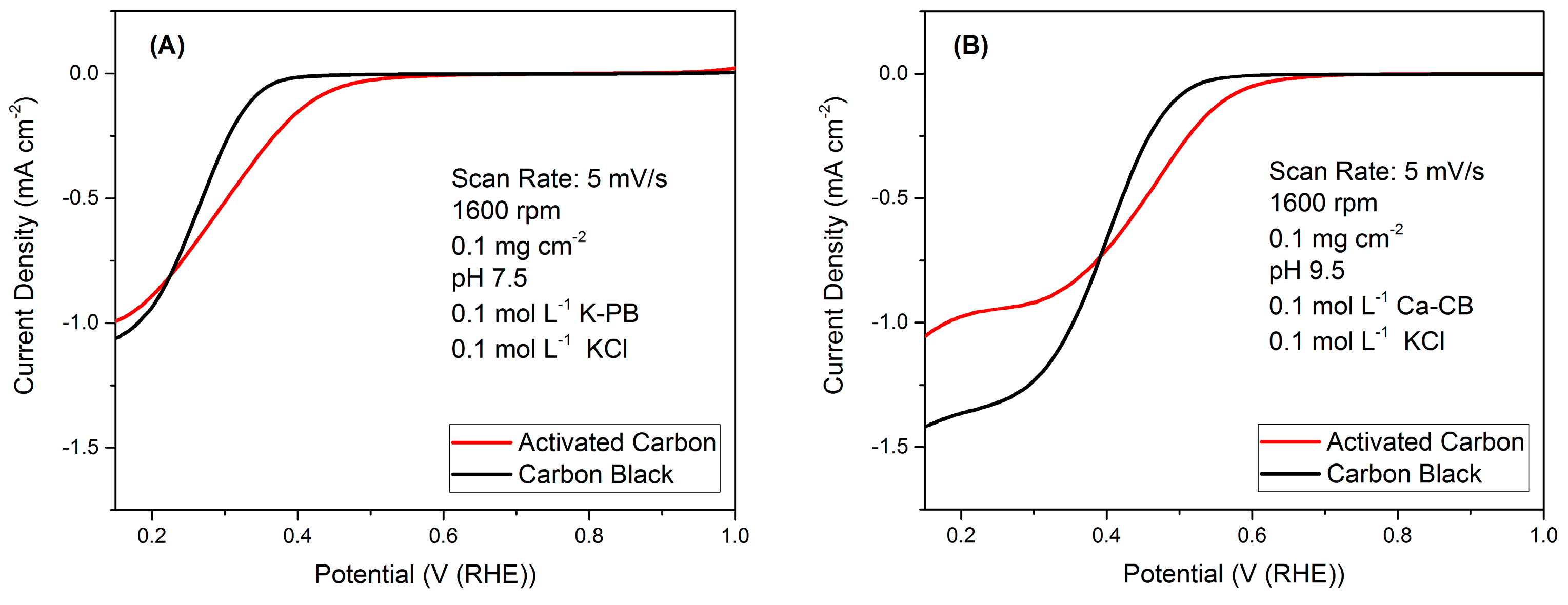
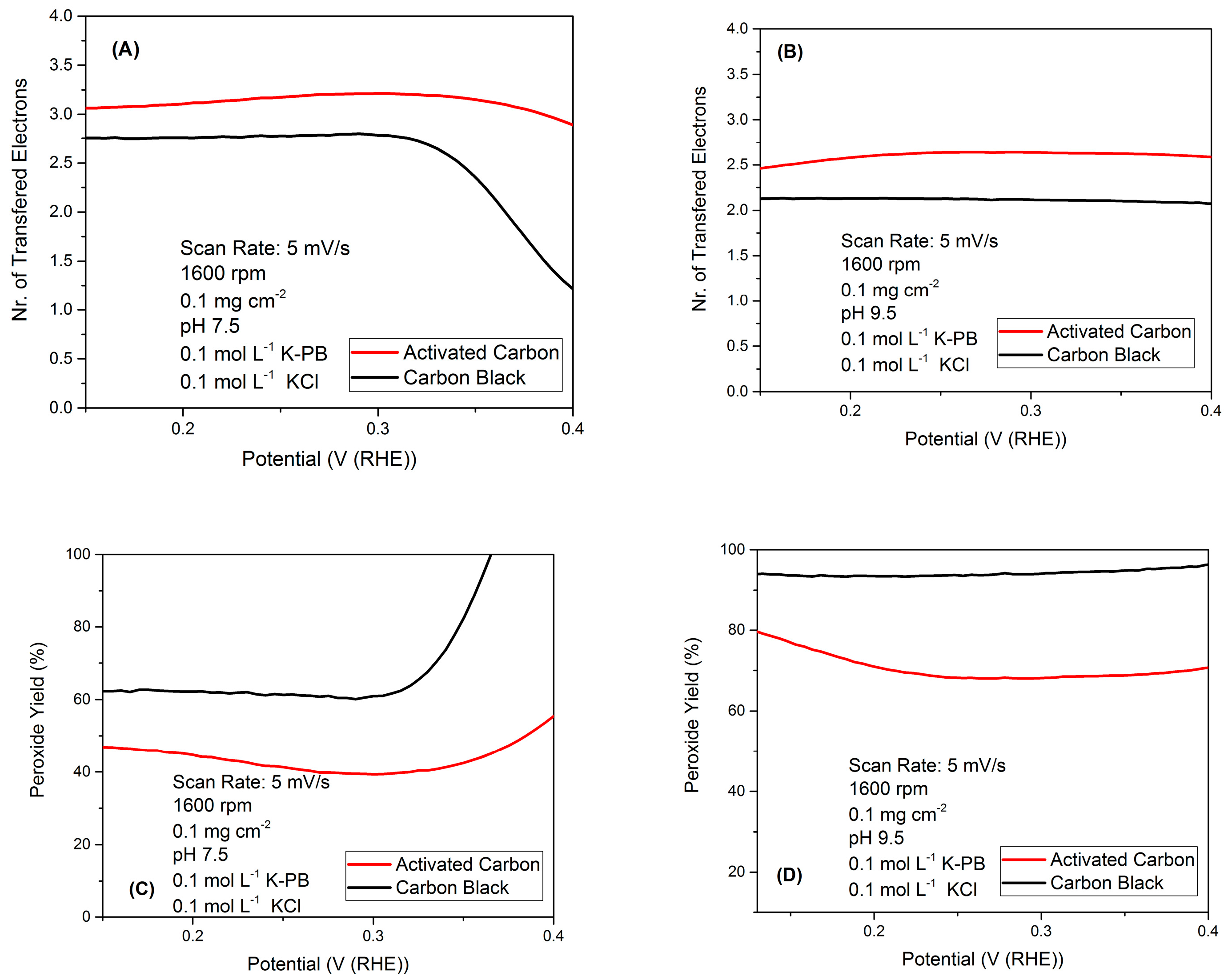
2.1. RRDE Results

Rotating ring disk electrode (RRDE) analysis on CB and AC at pH 7.5 (Figure 1a) and at pH 9.5 (Figure 1b) are shown. From the polarization curve that compares AC with CB, it is clear that the AC has a lower overpotential than CB, which implies better catalytic ability of the AC towards the ORR, as it has been studied in detail for other carbon containing materials [46]. This is also evidenced by the higher current densities of the AC in the mix regime region of the kinetic and transport-controlled regime. From the limiting current region, the carbon black has a slightly higher current density in both pH conditions (Figure 1), and this is expected due to the lower transport limitation that this material faced, due to the reduced amount of smaller pores in agreement with the pore size distribution showed in literature [47,48]. As for the case of the AC, nanometric pores contribute to a higher transport limitation, as the oxygen needs to diffuse into smaller features in order to be reduced [49,50]. Additionally, it is important to point out the higher open circuit potential for both materials at the more alkaline pH, which is an indicator of an electrolyte where carbon materials have a higher catalytic effect. This is expected due to the higher concentration of hydroxyl species, which have been demonstrated to be an important participant in the oxygen reduction reaction for other carbon-based materials [51].
In the RRDE setup, it is also possible to measure the amount of hydrogen peroxide produced during the ORR, as this peroxide is further reduced to water in the platinum ring that the probe possesses. This reduction current is measured and then used to estimate the amount of peroxide that the carbon black and activated carbon produced during the electrocatalytic reduction of oxygen. This is an important parameter, as the oxygen reduction to water or hydroxyls is a four e transfer process, whereas the reduction to hydrogen peroxide yields only two e. The formula that correlates the current measured at the disk and the current measured at the ring to estimate the amount of transferred electrons during the reduction reactions is (Equation (5)):
n = | 4 × j D j D j R |
where jD is the reductive current density measured at the disk and jR is the current measured at the ring, corrected by the collection efficiency for the used rotating ring disk electrode which, for our experiments, was 0.37, measured from the redox process of iron ferrocyanide, as it has been mentioned in our previous studies [52]. The number of electrons transferred by AC is always higher than CB at both pH levels investigated indicating that AC has higher electrocatalytic activity towards the ORR compared to CB (Figure 2). For the case of the experiments conducted at pH 7.5, there is a low measure of number of transferred electrons at potentials above 0.35 V (vs. Ag/AgCl). This is explained from the fact that the open circuit potential for this material is ca. 0.35 V as it is seen in the linear voltammetry from Figure 1. Therefore, above this potential, the methodology used for calculating the number of electrons is not meaningful. This also explains the high hydrogen peroxide yield estimated for this material at this pH for potentials above the open circuit potential, as it can be seen in Figure 2C and described below.
From the estimated number of transferred electrons, it is possible to then assess the amount of hydrogen peroxide that was produced during the electrocatalytic reduction of oxygen by employing Equation (6):
x = 4 n 2   ×   100
where n is the number of transferred electrons estimated from the disk and collection efficiency corrected ring current densities. From the results of the transferred electrons and the hydrogen peroxide yield (Figure 2), it can be seen that AC and CB perform the reduction of oxygen by producing hydrogen peroxide. In the case of the activated carbon, hydrogen peroxide is trapped inside of the high porosity that it possesses, reducing the amount of measured peroxide for this sample. Results indicated that the two e pathway with peroxide production is preferential.

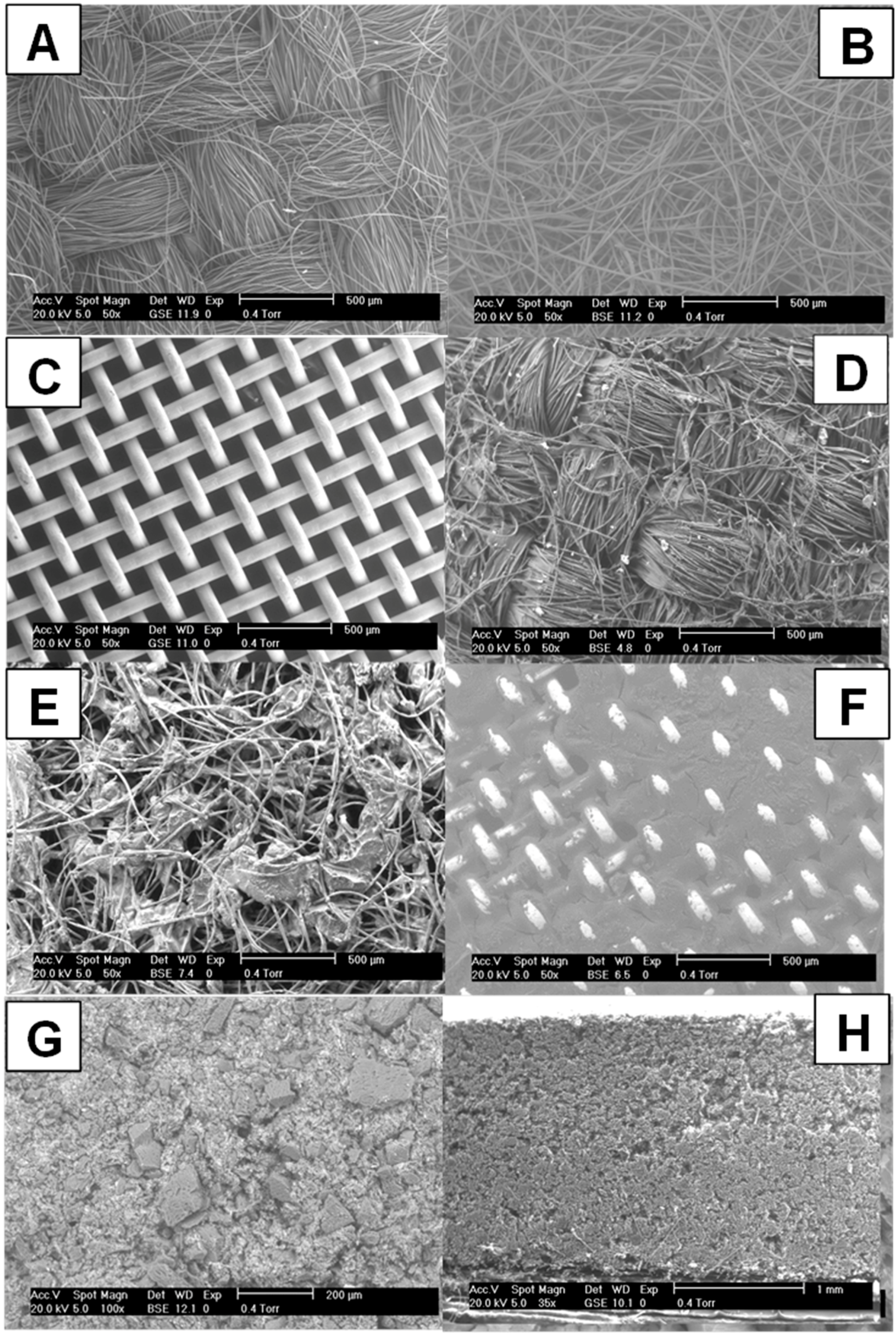
2.2. Electrode Characterization

Figure 3 shows the environmental scanning electron microscope (ESEM) pictures of the different supporting materials used for the cathode electrodes: (A) CC, (B) CF, and (C) SS; the supporting materials with the MPL layer: (D) CC + MPL, (E) CF + MPL, and (F) SS + MPL; and the front (G) and cross-section (H) of the AC layer on the cathode electrodes. Figure 3A–C show the difference in the material morphology and porosity of the different supporting materials. Figure 3D–F illustrate the MPL covering the supporting materials, however, in (E) some gaps between the carbon fibers can be appreciated, compared to (D) and (F). (H) and (G) show the AC layer, which shows a more homogeneous structure and less porousity. The thickness of the AC layer can be measured from (H), being approximately 1.8 mm.

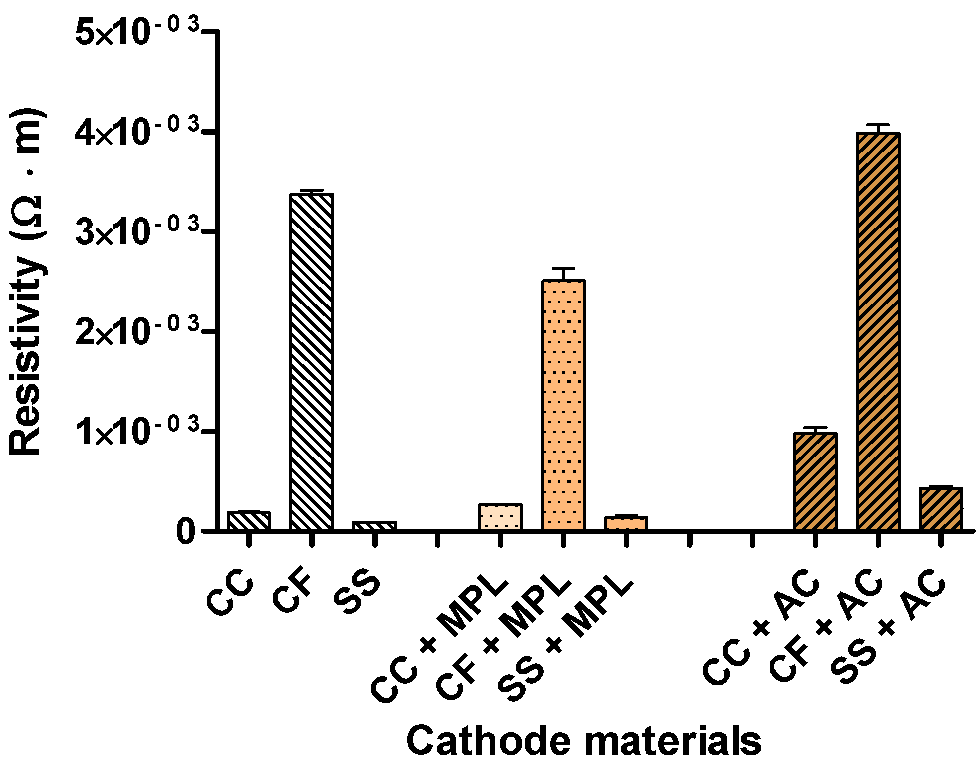
2.3. Electrode Resistivity

Figure 4 shows the electrical resistivity of the different supporting materials without a catalyst layer, with the MPL layer and with the AC layer. Being that the conductivity is the reciprocal of the resistivity, it is an important parameter that will affect the ohmic losses of the cathode and of the overall MFC. The results show in all cases a significant difference in the conductivity of the material with the following order: SS > CC > CF, underlining that the most conductive current collector was SS and the least conductive was CF. The same trend was obtained for the electrode with the MPL layer and with the AC layer. However, the addition of AC increased the resistivity and, thus, decreased the conductivity of the electrode material. In fact, AC possesses high surface area (890 m2·g−1) that is beneficial for the ORR but negatively affects the material conductivity.

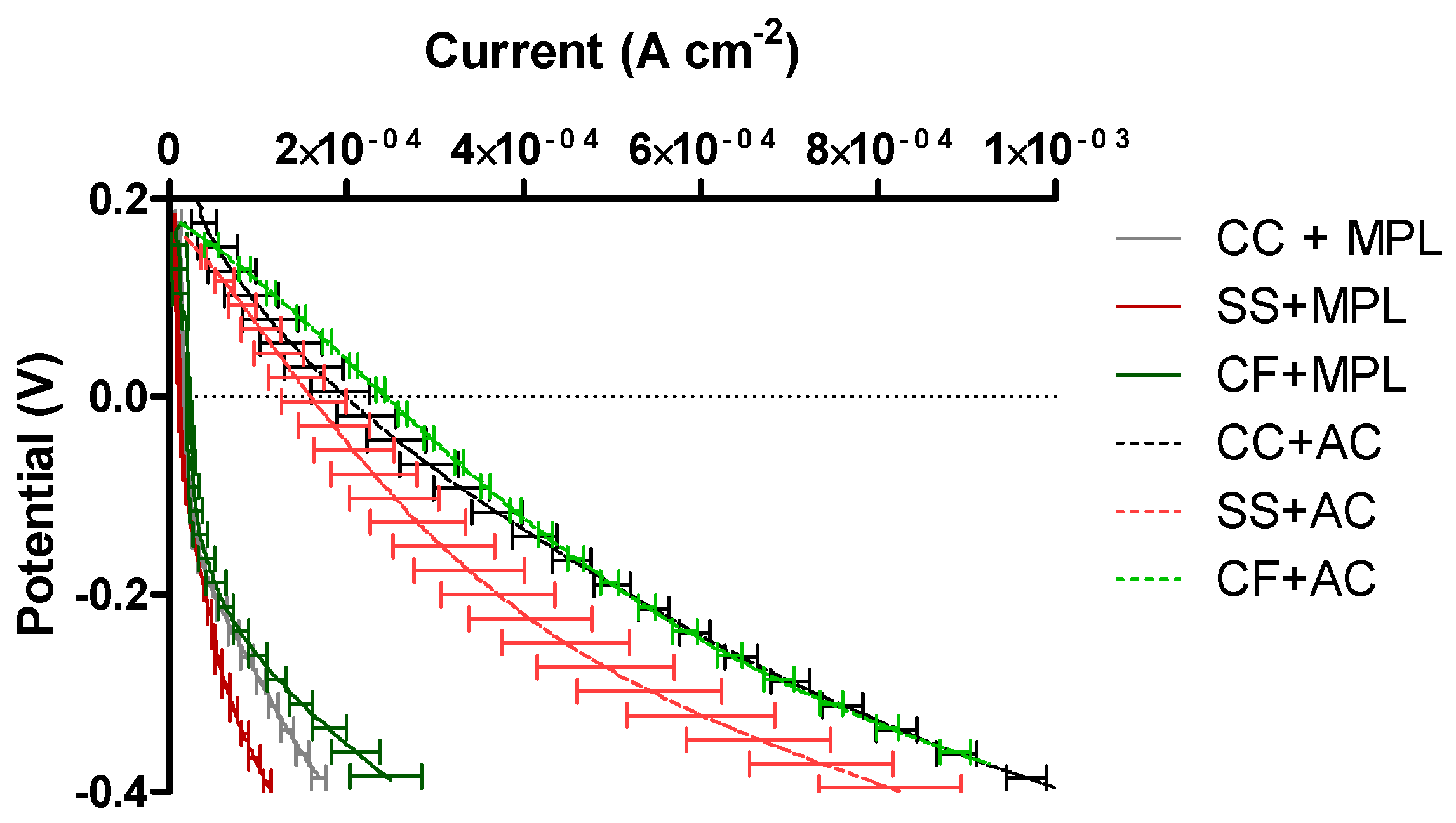
2.4. Cathode Polarization Curve in “Pristine” Conditions

The catalysts materials have been then incorporated into cathodes and further investigated. Figure 5 shows the linear sweep voltammetry of the different cathode electrodes. According to the results, all the MPL electrodes showed the same overpotentials, which was expected since the same catalyst was used. However, higher current was obtained from the CF + AC, followed by CC + AC, and the SS + AC, respectively. The electrodes containing CB showed significantly lower current density than those prepared with AC, which is in agreement with the results obtained from the RRDE. The same order was followed by the electrodes prepared with MPL and the different supporting materials, being CF + MPL was the electrode producing the highest current density, followed by the CC + MPL and by the SS + MPL. These results suggest no straight correlation between material resistivity and current produced. However, the resistance of each substratum material was also related with the thickness of the material, which is a critical factor for the oxygen diffusion in the gas diffusion layer. A thicker porous structure was obtained from the CF + MPL electrode than in the SS + MPL, probably allowing a better oxygen circulation and breathing and, consequently, improving the ORR. Moreover, a better three phase interface (TPI) could be maintained. In addition, the thickness of the CF supporting material increases the available carbon active sites for the ORR, being the oxygen reduced not only on the catalyst layer but also on the support material. This factor was more pronounced in the CF since it offers a thicker layer (higher surface area) than the CC, and being both higher than the SS which showed a poor catalysis towards ORR. That caused an increased current generation from the CF + MPL, higher than that of the CC + MPL, and followed by the SS + MPL.

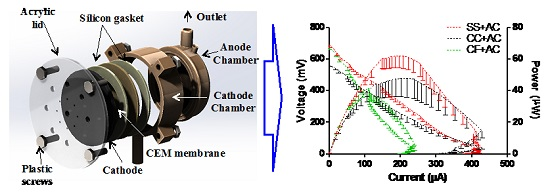
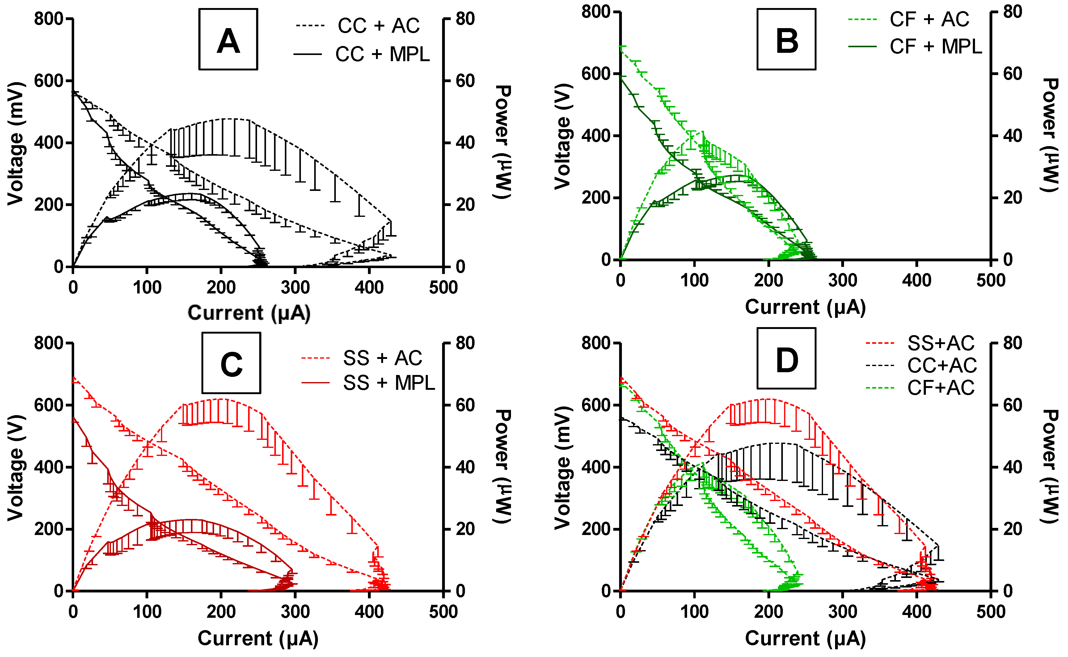
2.5. MFCs’ Power Performance

After single polarization curves were performed, the cathodes have been incorporated into the running MFCs. Figure 6 illustrates a comparison of the maximum power achieved from the polarization experiments performed on the MFCs for the duration of the experiment. In the figure, the effect of the different substratum materials on the power performance can be compared, as well as the comparison of the MPL layer (straight line) and the AC layer (dotted lines). The first polarization showed maximum power production of 27 ± 2, 23 ± 2, and 24 ± 5 μW, for MFCs 1–3 (CF + MPL), 4–6 (CC + MPL), and 7–9 (SS + MPL), respectively. This is in agreement with the linear sweep voltammetry (LSV) data, which showed that the highest current was obtained using CF + MPL, compared with CC + MPL and SS + MPL, respectively. The second polarization was carried out when the MFCs were using the different substratum materials (CF, CC, and SS) and AC as the catalyst. The polarization curves showed an increase of the maximum power generated by the MFCs due to the addition of the AC layer, reaching average values of 41 ± 5, 49 ± 11, and 62 ± 7 μW, for MFCs 1–3 (CF + AC), 4–6 (CC + AC), and 7–9 (SS + AC) containing cathodes with CF, CC and SS, substratum materials, respectively. However, the maximum power obtained from MFCs 7–9 (SS + AC) in the second polarization experiment was more than 50% higher than that obtained in the first polarization, when SS + MPL was used. The comparison of the substratum materials for the second polarization is shown in Figure 6D, where the cathode electrodes contained an AC layer. In this case, the cathode electrodes with the current collector having the highest conductivity (SS) contributed to a higher power production, followed by carbon cloth (CC) and carbon felt (CF). The same order, from more conductive to less conductive is followed in terms of power produced.

3. Materials and Methods

3.1. Electrode Preparation and Characterization

A total of six different cathode electrode types were prepared, consisting of two different catalyst layers: a microporous layer based on carbon black (MPL) and an activated carbon (AC) layer, spread on three different supporting materials: CC (Fuel Cell Earth, MA, USA), SS mesh (McMaster-Carr, Robbinsville, NJ, USA), and CF (Alfa Aesar, Haverhill, MA, USA, 3.18 mm thick, 99% purity). The MPL was prepared as previously described, mixing carbon black (CB, acetylene 50% compressed, Alfa Aesar, Haverhill, MA, USA), polytetrafluoroethylene (PTFE) as the binding agent (60% emulsion, Sigma-Aldrich, St. Louis, MO, USA) and a surfactant (Triton X100, Sigma-Aldrich, St. Louis, MO, USA) [53]. After heating treatment, CB was ≈83 wt % and PTFE was ≈17 wt % while the surfactant was fully decomposed. The AC catalyst layer was prepared by mixing commercial activated carbon (NORIT SX Ultra, Sigma-Aldrich, St. Louis, MO, USA) and PTFE (Sigma-Aldrich, St. Louis, MO, USA) with final weight percentages of 80% and 20%, respectively. The mixture was then inserted in a pellet die and pressed at 2 mT for 5 min on the different materials [54,55]. Brunauer-Emmett-Teller (BET) surface area was measured for both CB and AC. CB had a BET surface area of 72 m2·g−1 and AC had a surface area of 890 m2·g−1. Pore size distributions of the carbonaceous materials have been presented previously in the literature [47,48,49,50]. The cathode electrodes were cut in a circular shape with a diameter of 3.5 cm and a geometrical surface area of 9.6 cm2. A Philips XL30 environmental scanning electron microscope (ESEM, Philips, Eindhoven, The Netherlands) was used to obtain the images of the substratum materials and the electrodes. To increase the accuracy of the images in the microscope, the samples were gold coated using physical vapor deposition at 10 mA for 5 min using an Emscope SC500 sputter-coating unit (Quorum Technologies, Hertfordshire, UK).The anode electrode was prepared by cutting a plain carbon fiber veil sheet (30 g·m−2) with a surface area of 68 cm2 (PRF Composite Materials Poole, Dorset, UK), which was then folded five times and wrapped with a stainless steel wire (0.5 mm, Scientific Wire Company, Great Dunmow, UK), which was also serving as the current collector. The same procedure was followed to prepare and assemble all of the MFCs.

3.2. Electrical Resistivity

The electrical resistance was measured for each substratum material and cathode electrode using the four-wire resistance technique. A geometric surface of 2.25 cm2 (1.5 × 1.5 cm2) of each substratum material and each cathode electrode was cut. Constant current (300 mA) was applied to the material using a PSM-3004 (GW INSTEK, Tucheng, Taiwan) power supply. The voltage drop was then measured using a digital multimeter M-3850D (METEX, Seoul, Korea). The resistivity of the material (ρ), based on this resistance measurement, was then calculated, using Equation (7), considering the dimensions of each piece of material [56]:
ρ = L × R A
where ρ is the electrical resistivity of the material, L is the length of the material (usually expressed in m), A the cross-sectional area of the specimen (usually expressed in m2), and R is the electrical resistance of the material (usually expressed in Ω).

3.3. Rotating Ring Disk Electrode (RRDE) Analysis on Carbon Black and Activated Carbon Catalysts

Rotating ring disk electrode (RRDE) measurements were performed on CB and AC inks, prepared using the carbonaceous catalyst utilized during the MFC experiments. The inks were made by suspending 5 mg of the carbonaceous material, in a solution containing 0.075% of 1100 EW Nafion (FuelCellStore). This suspension was thoroughly dispersed by using a sonicator working at 3 W for 30 s. This sonication process was repeated 3 times. A loading of 100 μg·cm−2 was applied on the RRDE. Two different pHs (7.5 and 9.5) were investigated, simulating the urine environment. The solution with pH 7.5 was based on 0.1 mol·L−1 potassium phosphate solution (K-PB) and 0.1 mol·L−1 of KCl as the background electrolyte. The solution with pH 9.5 was based on 0.1 mol·L−1 calcium carbonate buffer (Ca-CB) and 0.1 mol·L−1 of KCl. In both cases, the solutions were saturated with oxygen.

3.4. Linear Sweep Voltammetry on Cathode Electrode

Linear sweep voltammetry (LSV) was performed in a three-electrode electrochemical cell, assembled as illustrated in Figure 7. A stainless steel mesh (33 cm2) was used as the counter electrode in the half-cell. The cathode electrodes of 1.76 cm2 to be tested were used as working electrodes. An Ag/AgCl reference electrode (3 mol·L−1 KCl) was introduced in a tube leading to a Luggin-Haber capillary which faced the working electrode. Luggin-Haber capillary was used to reduce the ohmic resistance of the liquid electrolyte. A voltage range from 0.2 V to −0.6 V vs. Ag/AgCl was scanned at 0.3 mV·s−1. A fresh abiotic phosphate buffer saline (PBS) solution of 0.1 mol·L−1 was used for each LSV (pH = 7.0) [55].

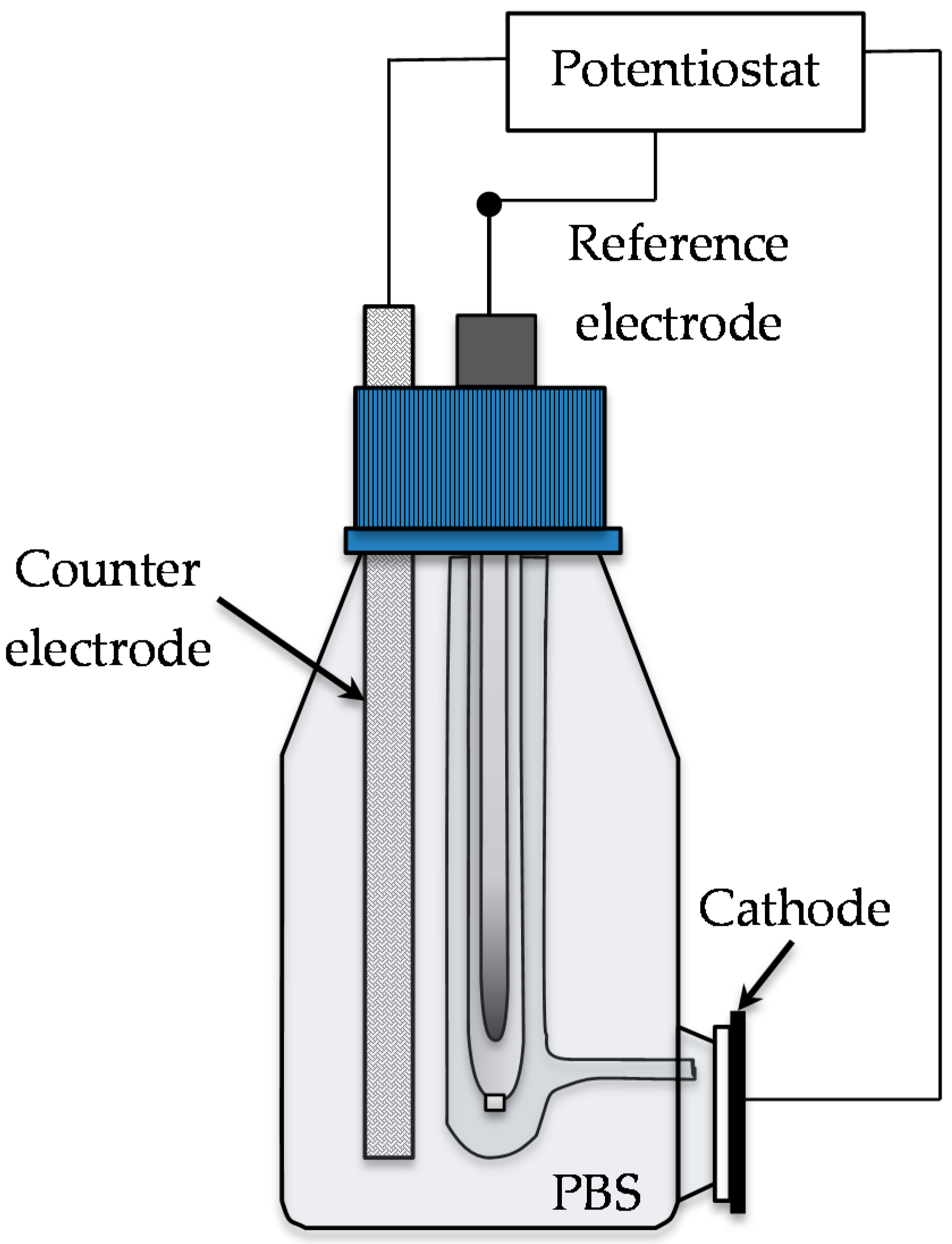
3.5. MFC Design and Operation

Figure 8 shows the MFCs design, which structure was 3D printed in nano-cure material, using a photo-stereolithography technique (EnvisionTec, Dearborn, MI, USA). The anodic chamber, with an internal volume of 6.25 cm3, contained an inlet and outlet orifices (4 mm diameter) in the bottom and top, respectively, for continuous flow operation. A cationic exchange membrane (CMI-7000, Membrane International, Ringwood, NJ, USA) of 3.5 cm diameter, was used to separate the anode and the cathode chambers. The air cathodes were sandwiched between the membrane and a stainless steel woven mesh (0.6 mm, Scientific Wire Company, Essex, UK), which was used as the current collector. Silicon gaskets were introduced in both sides of the membrane to avoid leakages. An acrylic circular lid of 5.1 cm diameter was screwed to the anode chamber closing the MFC and avoiding excessive drying out of the membrane, but allowing oxygen to diffuse through 1 mm holes.

3.6. Testing of Different Cathode Electrodes

A total of nine MFCs were assembled with similar electrodes and under the same conditions as previously reported [2,45]. Once the MFCs reached a stable and comparable output, the cathode was then changed with the materials of interest. After seven days of continuous experiments, the cathodes were then replaced in the following way: MFCs 1–3 CF + AC, MFCs 4–6 CC + AC, MFCs 7–9 SS + AC. The cathode electrodes could be easily replaced by opening the acrylic lid and changing the electrode without disturbing the anodic compartment.

3.7. MFC Monitoring

An ADC-24 Channel Data Logger (Pico Technology Ltd., Cambridgeshire, UK) was connected to a computer for real-time the voltage (V) monitoring of each MFC. The recorded data were processed using GraphPad Prism version 5.04 software package (GraphPad, San Diego, CA, USA, 2010).

3.8. Inoculation and Polarization

The inoculation process was carried out in batch mode using a mixture of 50:50 fresh urine and activated sludge. The urine was donated by random individuals with a normal diet and no medical conditions. The activated sewage sludge supplied from Wessex Water Scientific Laboratory (Saltford, UK). The MFCs were fed with the sludge/urine mix once per day for three consecutive days. The first day, the MFCs remained at open circuit for two hours and then a 2 kΩ external resistance was connected to each MFC. After the third day, a continuous mode feeding with only fresh urine was setup at a flow rate of 9.52 mL·h−1 (hydraulic retention time—HRT = 37 min). A 16-channel peristaltic pump (205 U, Watson Marlow, Falmouth, UK) was used to continuously pump the anolyte. All experiments were performed at room temperature 22 ± 2 °C. Polarization experiments were performed to find out the maximum power achievable by the MFCs. The system remained open circuit until it reached steady state (approximately one hour) before the polarization started. A DR07 decade variable resistor box (ELC, Annecy, France) was used to apply external resistances from 30 KΩ to 3 Ω, changed every 3 min. The current and power generated by the MFCs were calculated using Ohm’s law (I = V/R) and P = V × I with a known external resistance value.

4. Conclusions

Carbon-based electrode materials have been tested as cathodes for MFCs treating urine. The electrodes consisted of a microporous layer (MPL) based on carbon black (CB) and an activated carbon (AC) layer applied on different supporting materials, including carbon cloth (CC), carbon felt, (CF) and stainless steel (SS). Electrochemical analysis, including RRDE and LSV, showed that the AC has an increased catalytic ORR activity, leading to an enhanced MFC power output compared with the CB-based catalyst layer. The number of electrons released during the reduction process suggested a hydrogen peroxide pathway involving two electrons for the CB and AC, at pH 7.5 and 9.5. The MFC’s performance with the different electrode materials could also be evaluated suggesting that activated carbon (AC) on stainless steel (SS) was the most effective cathode electrode for the MFCs, followed by AC on CC.

Acknowledgments

The authors would like to acknowledge the Bill and Melinda Gates Foundation, which funded part of this work under the grant No. OPP1094890. The authors would also like to thank the Bill and Melinda Gates Foundation grant: “Efficient Microbial Bio-electrochemical Systems” (OPP1139954).

Author Contributions

S.R.-C. performed the RRDE experiments. I.M.-J. performed the experiments in operating MFC. All the authors conceived and designed the experiments, analyzed the data and wrote the paper.

Conflicts of Interest

The authors declare no conflict of interest.

References

  1. Pandey, P.; Shinde, V.N.; Deopurkar, R.L.; Kale, S.P.; Patil, S.A.; Pant, D. Recent advances in the use of different substrates in microbial fuel cells toward wastewater treatment and simultaneous energy recovery. Appl. Energy 2016, 168, 706–723. [Google Scholar] [CrossRef]
  2. Ieropoulos, I.; Winfield, J.; Gajda, I.; Walter, A.; Papaharalabos, G.; Merino-Jimenez, I.; Pasternak, G.; You, J.; Tremouli, A.; Stinchcombe, A.; et al. Chapter 12: The practical implementation of microbial fuel cell technology. In Microbial Electrochemical and Fuel Cells; Woodhead Publishing/Elsevier: Cambridge, UK, 2015; pp. 357–380. [Google Scholar]
  3. Ieropoulos, I.; Ledezma, P.; Stinchcombe, A.; Papaharalabos, G.; Melhuish, C.; Greenman, J. Waste to real energy: The first MFC powered mobile phone. Phys. Chem. Chem. Phys. 2013, 15, 15312–15316. [Google Scholar] [CrossRef] [PubMed]
  4. Melhuish, C.; Ieropoulos, I.; Greenman, J.; Horsfield, I. Energetically autonomous robots: Food for thought. Auton. Robot. 2006, 21, 187–198. [Google Scholar] [CrossRef]
  5. Ieropoulos, I.; Greenman, J.; Melhuish, C.; Horsfield, I. EcoBot-III: A robot with guts. In Proceedings of the Alife XII Conference, Odense, Denmark, 19–23 August 2010.
  6. Ieropoulos, I.A.; Stinchcombe, A.; Gajda, I.; Forbes, S.; Merino-Jimenez, I.; Pasternak, G.; Sanchez-Herranz, D.; Greenman, J. Pee power urinal—Microbial fuel cell technology field trials in the context of sanitation. Environ. Sci. Water Res. Technol. 2016, 2, 336–343. [Google Scholar] [CrossRef]
  7. Liu, H.; Ramnarayanan, R.; Logan, B.E. Production of electricity during wastewater treatment using a single chamber microbial fuel cell. Environ. Sci. Technol. 2004, 38, 2281–2285. [Google Scholar] [CrossRef] [PubMed]
  8. Min, B.; Kim, J.R.; Oh, S.E.; Regan, J.M.; Logan, B.E. Electricity generation from swine wastewater using microbial fuel cells. Water Res. 2005, 39, 4961–4968. [Google Scholar] [CrossRef] [PubMed]
  9. Wei, J.; Liang, P.; Huang, X. Recent progress in electrodes for microbial fuel cells. Bioresour. Technol. 2011, 102, 9335–9344. [Google Scholar] [CrossRef] [PubMed]
  10. Hamelers, H.V.M.; TerHeijne, A.; Sleutels, T.H.J.A.; Jeremiasse, A.W.; Strik, D.P.B.T.B.; Buisman, C.J.N. New applications and performance of bioelectrochemical systems. Appl. Microbiol. Biotechnol. 2010, 85, 1673–1685. [Google Scholar] [CrossRef] [PubMed]
  11. Franks, A.E.; Nevin, K.P. Microbial fuel cells, a current review. Energies 2010, 3, 899–919. [Google Scholar] [CrossRef]
  12. Rismani-Yazdi, H.; Carver, S.M.; Christy, A.D.; Tuovinen, O.H. Cathodic limitations in microbial fuel cells: An overview. J. Power Sources 2008, 180, 683–694. [Google Scholar] [CrossRef]
  13. Cristiani, P.; Carvalho, M.L.; Guerrini, E.; Daghio, M.; Santoro, C.; Li, B. Cathodic and anodic biofilms in single chamber microbial fuel cells. Bioelectrochemistry 2013, 92, 6–13. [Google Scholar] [CrossRef] [PubMed]
  14. Santoro, C.; Cremins, M.; Pasaogullari, U.; Guilizzoni, M.; Casalegno, A.; Mackay, A.; Li, B. Evaluation of water transport and oxygen presence in single chamber microbial fuel cells with carbon-based cathodes. J. Electrochem. Soc. 2013, 160, 128–134. [Google Scholar] [CrossRef]
  15. Liu, H.; Logan, B.E. Electricity generation using an air-cathode single chamber microbial fuel cell in the presence and absence of a proton exchange membrane. Environ. Sci. Technol. 2004, 38, 4040–4046. [Google Scholar] [CrossRef] [PubMed]
  16. Min, B.; Logan, B.E. Continuous electricity generation from domestic wastewater and organic substrates in a flat plate microbial fuel cell. Environ. Sci. Technol. 2004, 38, 5809–5814. [Google Scholar] [CrossRef] [PubMed]
  17. Pham, T.H.; Jang, J.K.; Moon, H.S.; Chang, I.S.; Kim, B.H. Improved performance of microbial fuel cell using membrane-electrode assembly. J. Microbiol. Biotechnol. 2005, 15, 438–441. [Google Scholar]
  18. Kim, M.; Hyun, M.S.; Gadd, G.M.; Kim, G.T.; Lee, S.J.; Kim, H.J. Membrane-electrode assembly enhances performance of a microbial fuel cell type biological oxygen demand sensor. Environ. Technol. 2009, 30, 329–336. [Google Scholar] [CrossRef] [PubMed]
  19. Kim, J.R.; Min, B.; Logan, B.E. Evaluation of procedures to acclimate a microbial fuel cell for electricity production. Appl. Microbiol. Biotechnol. 2005, 68, 23–30. [Google Scholar] [CrossRef] [PubMed]
  20. Santoro, C.; Guilizzoni, M.; Correa Baena, J.P.; Pasaogullari, U.; Casalegno, A.; Li, B.; Babanova, S.; Artyushkova, K.; Atanassov, P. The effect of carbon surface properties on bacteria attachment and start up time of microbial fuel cells. Carbon 2014, 67, 128–139. [Google Scholar] [CrossRef]
  21. Rabaey, K.; Rodrıguez, J.; Blackall, L.L.; Keller, J.; Gross, P.; Batstone, D.; Verstrate, W.; Nealson, K.H. Microbial ecology meets electrochemistry: Electricity-driven and driving communities. ISME J. 2007, 1, 9–18. [Google Scholar] [CrossRef] [PubMed]
  22. Ishii, S.; Suzuki, S.; Norden-Krichmar, T.M.; Phan, T.; Wanger, G.; Nealson, K.H.; Sekiguchi, Y.; Gorby, Y.A.; Bretschger, O. Microbial population and functional dynamics associated with surface potential and carbon metabolism. ISME J. 2014, 8, 963–978. [Google Scholar] [CrossRef] [PubMed]
  23. Ishii, S.; Suzuki, S.; Norden-Krichmar, T.M.; Wu, A.; Yamanaka, Y.; Nealson, K.H.; Bretschger, O. Identifying the microbial communities and operational conditions for optimized wastewater treatment in microbial fuel cells. Water Res. 2013, 47, 7120–7130. [Google Scholar] [CrossRef] [PubMed]
  24. Xafenias, N.; Mapelli, V. Performance and bacterial enrichment of bioelectrochemical systems during methane and acetate production. Int. J. Hydrog. Energy 2014, 39, 21864–21875. [Google Scholar] [CrossRef]
  25. Erable, B.; Feron, D.; Bergel, A. Microbial catalysis of the oxygen reduction reaction for microbial fuel cells: A review. ChemSusChem 2012, 5, 975–987. [Google Scholar] [CrossRef] [PubMed] [Green Version]
  26. Lakshminarayanaiah, N. Transport Phenomena in Membranes; Academic Press: New York, NY, USA, 1969. [Google Scholar]
  27. Fischer, P.; Heitbaum, J. Mechanistic aspects of cathodic oxygen reduction. J. Electroanal. Chem. 1980, 112, 231–238. [Google Scholar] [CrossRef]
  28. Pivovar, B.S.; Smyrl, W.; Cussler, E.L. Electro-osmosis in Nafion 117, Polystyrene Sulfonic Acid, and Polybenzimidazole. J. Electrochem. Soc. 2005, 152, A53–A60. [Google Scholar] [CrossRef]
  29. Verbrugge, M.W.; Hill, R.F. Ion and solvent transport in ion-exchange membranes. J. Electrochem. Soc. 1990, 137, 886–893. [Google Scholar] [CrossRef]
  30. Hao, X.D.; Wang, C.C.; Lan, L.; Von Loosdrecht, M.C.M. Struvite formation, analytical methods and effects of pH and Ca2+. Water Sci. Technol. 2008, 58, 1687–1692. [Google Scholar] [CrossRef] [PubMed]
  31. Gu, L.; Luo, N.; Miley, G.H. Cathode electrocatalyst selection and deposition for a direct borohydride/hydrogen peroxide fuel cell. J. Power Sources 2007, 173, 77–85. [Google Scholar] [CrossRef]
  32. Feng, Y.; Shi, X.; Wang, X.; Lee, H.; Liu, J.; Qu, Y.; He, W.; Senthil Kumar, S.M.; Kim, B.H.; Ren, N. Effects of sulfide on microbial fuel cells with platinum and nitrogen- doped carbon powder cathodes. Biosens. Bioelectron. 2012, 35, 413–415. [Google Scholar] [CrossRef] [PubMed]
  33. Santoro, C.; Serov, A.; Stariha, L.; Kodali, M.; Gordon, J.; Babanova, S.; Bretschger, O.; Artyushkova, K.; Atanassov, P. Iron based catalysts from novel low-cost organic precursors for enhanced oxygen reduction reaction in neutral media microbial fuel cells. Energy Environ. Sci. 2016, 9, 2346–2353. [Google Scholar] [CrossRef]
  34. Rinaldi, A.; Mecheri, B.; Garavaglia, V.; Licoccia, S.; Di Nardo, P.; Traversa, E. Engineering materials and biology to boost performance of microbial fuel cells: A critical review. Energy Environ. Sci. 2009, 1, 417–429. [Google Scholar] [CrossRef] [Green Version]
  35. Liew, K.B.; Wan Daud, W.R.; Ghasemi, M.; Leonga, J.X.; Lima, S.S.; Ismail, M. Non-Pt catalyst as oxygen reduction reaction in microbial fuel cells: A review. Int. J. Hydrog. Energy 2014, 39, 4870–4883. [Google Scholar] [CrossRef]
  36. Cheng, S.A.; Liu, H.; Logan, B.E. Power densities using different cathode catalysts (Pt and CoTMPP) and polymer binders (Nafion and PTFE) in single chamber microbial fuel cells. Environ. Sci. Technol. 2006, 40, 364–369. [Google Scholar] [CrossRef] [PubMed]
  37. Zhao, F.; Harnisch, F.; Schroder, U.; Scholz, F.; Bogdanoff, P.; Herrmann, I. Application of pyrolysed iron (II) phthalocyanine and CoTMPP based oxygen reduction catalysts as cathode materials in microbial fuel cells. Electrochem. Commun. 2005, 7, 1405–1410. [Google Scholar] [CrossRef]
  38. Hernández-Fernández, F.J.; Pérez de los Ríos, A.; Salar-García, M.J.; Ortiz-Martínez, V.M.; Lozano-Blanco, L.J.; Godínez, C.; Tomás-Alonso, F.; Quesada-Medina, J. Recent progress and perspectives in microbial fuel cells for bioenergy generation and wastewater treatment. Fuel Process. Technol. 2015, 138, 284–297. [Google Scholar] [CrossRef]
  39. Antolini, E. Composite materials for polymer electrolyte membrane microbial fuel cells. Biosens. Bioelectron. 2015, 69, 54–70. [Google Scholar] [CrossRef] [PubMed]
  40. Yuan, H.; Hou, Y.; Reesh, I.M.A.; Chen, J.; He, Z. Oxygen reduction reaction catalysts in microbial fuel cells for energy-efficient wastewater treatment: A review. Mater. Horiz. 2016. [Google Scholar] [CrossRef]
  41. Mustakeem, M. Electrode materials for microbial fuel cells: Nanomaterial approach. Mater. Renew. Sustain. Energy 2015, 4. [Google Scholar] [CrossRef]
  42. Wang, Z.; Cao, C.; Zheng, Y.; Chen, S.; Zhao, F. Abiotic oxygen reduction reaction catalysts used in microbial fuel cells. ChemElectroChem 2014, 1, 1813–1821. [Google Scholar] [CrossRef]
  43. Watanabe, K. Recent developments in microbial fuel cell technologies for sustainable bioenergy. J. Biosci. Bioeng. 2008, 106, 528–536. [Google Scholar] [CrossRef] [PubMed]
  44. Santoro, C.; Agrios, A.; Pasaogullari, U.; Li, B. Effect of gas diffusion layer (GDL) and microporous layer (MPL) on cathode performance in microbial fuel cells. Int. J. Hydrog. Energy 2011, 36, 13096–13104. [Google Scholar] [CrossRef]
  45. Papaharalabos, G.; Greenman, J.; Melhuish, C.; Santoro, C.; Cristiani, P.; Li, B.; Ieropoulos, I. Increased power output from micro porous layer (MPL) cathode microbial fuel cells (MFC). Int. J. Hydrog. Energy 2013, 38, 11552–11558. [Google Scholar] [CrossRef]
  46. Artyushkova, K.; Serov, A.; Rojas-Carbonell, S.; Atanassov, P. Chemistry of Multitudinous Active Sites for Oxygen Reduction Reaction in Transition Metal–Nitrogen–Carbon Electrocatalysts. J. Phys. Chem. C 2015, 119, 25917–25928. [Google Scholar] [CrossRef]
  47. Park, S.S.; Jung, Y. Influence of the Electrode Materials on the Electrochemical Performance of Room Temperature Li-SO2 Rechargeable Battery. Int. J. Electrochem. Sci. 2015, 10, 7574–7581. [Google Scholar]
  48. Jhi, S.-H.; Kwon, Y.-K.; Bradley, K.; Gabriel, J.-C.P. Hydrogen storage by physisorption: Beyond carbon. Solid State Commun. 2004, 129, 769–773. [Google Scholar] [CrossRef]
  49. Fang, B.; Kim, J.H.; Kim, M.-S.; Bonakdarpour, A.; Lam, A.; Wilkinson, D.P.; Yu, S.-J. Fabrication of hollow core carbon spheres with hierarchical nanoarchitecture for ultrahigh electrical charge storage. J. Mater. Chem. 2012, 22, 19031–19038. [Google Scholar] [CrossRef]
  50. Gamby, J.; Taberna, P.L.; Simon, P.; Fauvarque, J.F.; Chesneau, M. Studies and characterisations of various activated carbons used for carbon/carbon supercapacitors. J. Power Sources 2001, 101, 109–116. [Google Scholar] [CrossRef]
  51. Tylus, U.; Jia, Q.; Strickland, K.; Ramaswamy, N.; Serov, A.; Atanassov, P.; Mukerjee, S. Elucidating oxygen reduction active sites in pyrolyzed metal–nitrogen coordinated non-precious-metal electrocatalyst systems. J. Phys. Chem. C 2014, 118, 8999–9008. [Google Scholar] [CrossRef] [PubMed]
  52. Robson, M.H.; Serov, A.; Artyushkova, K.; Atanassov, P. A mechanistic study of 4-aminoantipyrine and iron derived non-platinum group metal catalyst on the oxygen reduction reaction. Electrochim. Acta 2013, 90, 656–665. [Google Scholar] [CrossRef]
  53. Santoro, C.; Lei, Y.; Li, B.; Cristiani, P. Power generation from wastewater using single chamber microbial fuel cells (MFCs) with platinum-free cathodes and pre-colonized anodes. Biochem. Eng. J. 2012, 62, 8–16. [Google Scholar] [CrossRef]
  54. Gajda, I.; Greenman, J.; Melhuish, C.; Ieropoulos, I. Simultaneous electricity generation and microbially-assisted electrosynthesis in ceramic MFCs. Bioelectrochemistry 2015, 104, 58–64. [Google Scholar] [CrossRef] [PubMed]
  55. Santoro, C.; Artyushkova, K.; Babanova, S.; Atanassov, P.; Ieropoulos, I.; Grattieri, M.; Cristiani, P.; Trasatti, S.; Li, B.; Schuler, A.J. Parameters Characterization and Optmization of Activated Carbon (AC) Cathodes for Microbial Fuel Cell Applications. Bioresour. Technol. 2014, 163, 54–63. [Google Scholar] [CrossRef] [PubMed]
  56. You, J.; Greenman, J.; Melhuish, C.; Ieropoulos, I. Electricity generation and struvite recovery from human urine using microbial fuel cells. J. Chem. Technol. Biotechnol. 2015, 91, 647–654. [Google Scholar] [CrossRef]
Figure 1. Polarization curve of activated carbon and carbon black, rotation speed of 1600 RPM with pH 7.5 (A) and pH 9.5 (B) with an oxygen-saturated electrolyte.
Catalysts 06 00127 g001
Figure 2. Estimated number of transferred electrons for the AC (activated carbon) and CB (carbon black) from the RRDE (rotating ring disk electrode) measurements at pH 7.5 (A) and pH 9.5 (B). The estimated peroxide yield for the AC and CB from the RRDE measurements at pH 7.5 (C) and pH 9.5 (D).
Catalysts 06 00127 g002
Figure 3. Environmental scanning electron microscope (ESEM) images of the different substratum materials: (A) CC (carbon cloth); (B) CF (carbon felt); (C) (SS stainless steel) mesh; supporting materials with the MPL (micro-porous layer): (D) CC + MPL; (E) CF + MPL; (F) SS + MPL; AC layer, no substratum: (G) front view and (H) side view.
Catalysts 06 00127 g003
Figure 4. Electrical resistivity of the different substratum materials and cathode electrodes with a MPL layer and an AC layer.
Catalysts 06 00127 g004
Figure 5. Linear sweep voltammetry of the different cathode electrodes tested at pH 7.5.
Catalysts 06 00127 g005
Figure 6. Comparison of the polarization curves of the MFCs (microbial fuel cells) with CB (straight line) and AC (dotted line) on the different substratum materials: (A) black CC; (B) green CF; and (C) red SS; and comparison of the MFCs’ performance using AC on different substratum materials (D).
Catalysts 06 00127 g006
Figure 7. Sketch of the three electrode electrochemical setup for LSV (linear sweep voltammetry) measurement.
Catalysts 06 00127 g007
Figure 8. (A) 3D Computer-Aided Design (CAD) MFCs design; and (B) a picture of the MFCs under operation.
Catalysts 06 00127 g008

