Review

TiO2 Solar Photocatalytic Reactor Systems: Selection of Reactor Design for Scale-up and Commercialization—Analytical Review

1
Environmental Engineering, American University in Cairo, Cairo 11835, Egypt
2
Department of Construction Engineering, American University in Cairo, Cairo 11835, Egypt
3
Department of Chemistry, American University in Cairo, Cairo 11835, Egypt
*
Author to whom correspondence should be addressed.
Catalysts 2016, 6(9), 138; https://doi.org/10.3390/catal6090138
Submission received: 25 July 2016 / Revised: 31 August 2016 / Accepted: 1 September 2016 / Published: 10 September 2016

Abstract

:
For the last four decades, viability of photocatalytic degradation of organic compounds in water streams has been demonstrated. Different configurations for solar TiO2 photocatalytic reactors have been used, however pilot and demonstration plants are still countable. Degradation efficiency reported as a function of treatment time does not answer the question: which of these reactor configurations is the most suitable for photocatalytic process and optimum for scale-up and commercialization? Degradation efficiency expressed as a function of the reactor throughput and ease of catalyst removal from treated effluent are used for comparing performance of different reactor configurations to select the optimum for scale-up. Comparison included parabolic trough, flat plate, double skin sheet, shallow ponds, shallow tanks, thin-film fixed-bed, thin film cascade, step, compound parabolic concentrators, fountain, slurry bubble column, pebble bed and packed bed reactors. Degradation efficiency as a function of system throughput is a powerful indicator for comparing the performance of photocatalytic reactors of different types and geometries, at different development scales. Shallow ponds, shallow tanks and fountain reactors have the potential of meeting all the process requirements and a relatively high throughput are suitable for developing into continuous industrial-scale treatment units given that an efficient immobilized or supported photocatalyst is used.

Graphical Abstract

1. Introduction

In the mid-1970s, the viability of photocatalytic degradation of organic compounds in water using titanium dioxide (TiO2) was demonstrated by several research groups [1]. Since that time, there was an increase in research done using TiO2 for photo-oxidation of organic compounds, inorganic compounds, metal-containing ions as well as disinfection. More than 1000 substances have been tested [2]. Advanced oxidation using TiO2 offer potential treatment opportunities for: tertiary treatment of municipal wastewater [3,4], for removal of endocrine disrupting chemicals [5,6,7] and disinfection [8,9], especially effluents containing pathogens resistant to chlorination [10,11,12,13,14,15,16]; treatment of hazardous effluents from hospitals [17,18]; industrial effluents from pulp and paper [19,20,21,22], dairy manufacturing [23], textile dyeing [24,25,26,27,28,29,30,31], agricultural oil mills and distilleries [32,33], and pharmaceutical industry [34,35,36,37]; wastewater effluents containing phenols [38,39,40,41] and chlorophenols [42,43], herbicides and pesticides [44,45,46], ammonia [47,48] plasticizers [49] and surfactants [50]; drinking water disinfection [51]; and purification from micro-pollutants [52], cyanide [53,54] and arsenic [55,56].
In the late-1980s, parabolic trough concentrator was used for the first field demonstration for solar heterogeneous photocatalytic water treatment tests [57]. Despite the extensive research on photocatalytic oxidation using TiO2, pilot and demonstration plants through the last four decades are still countable [1], [57,58,59,60,61,62,63,64,65,66] as shown in Table 1.
Different reactor configurations have been used to degrade various types of pollutants using solar light or artificial light simulating sunlight. However, which of these reactor configurations is the most suitable for the photocatalytic process and is optimum for scale-up and commercialization? The aim of this paper is to find an evaluation criterion to ease performance comparison and selection of a reactor configuration optimum for scale-up into an industrial scale and commercialization.
The quantum yield, which is the ratio of rate of reaction to rate of light absorption, was used by some researchers to demonstrate photoreactor energy efficiency [76]. The quantum yield was further modified into photochemical thermodynamic efficiency factor [77], which is given as:
η = Q used Q absorbed = r OH × Δ H OH × W Q absorbed
where rOH is the rate of OH radicals formation (mol/g of catalyst) ΔOH is the enthalpy of OH radicals formation (J/mol) and W is mass of catalyst (g). In addition to the difficulty of determining these energy efficiency factors [78], they cannot be used for the intended reactor configuration comparison. Two other parameters are of extreme importance for scale-up and commercialization of photocatalytic wastewater treatment: the treated volume, and the reactor foot print.
Figures of merit in terms of collector area per mass (ACM) and collector area per order (ACO) were proposed for comparison of advanced oxidation technologies (AOTs) reactors of different configurations based on the collector area. Collector area per mass (ACM) is the collector area required to degrade 1 kg of pollutant in one hour after receiving solar radiation of intensity 1000 W/m2 while collector area per order (ACO) is the collector area required to decrease the pollutant concentration of 1 m3 by one order of magnitude [79].
A C M = A r × E ¯ s × t × 1000 M × V t × E s o × t o ( c i c f )
A CO = A r × E ¯ s × t   V t × E s o × t o × log c i c f
where ACM and ACO are in m2/kg and m2/m3-order, respectively, Ar is the actual reactor area (m2), t and to are irradiance and reference time (h), E ¯ s and E s o are average solar irradiance and reference solar irradiance (W/m2), Vt treated volume (L), M molar mass g/mol, and ci and cf are initial and final pollutant molar concentrations, respectively. Collector area per mass has been used by researchers to compare performances of reactors of different configurations based on estimate of area required for scale-up [80,81]. For the cases in which the treated volumes/degraded pollutants are much lower than the proposed 1 m3 treated volume and 1 kg of pollutant identified by the proposed figures of merit, ACM and ACO figures of merit will be extrapolated indicators [58] not real reflection of the system performance. Hence, figures of merit will not be used for reactor performance comparison.
For a given degradation efficiency, reactor throughput (L/min/m2) will be used as an actual indicator on the treatment unit production rate based on the area it occupies. In case of batch operations, reactor throughput is the volume treated/total treatment time/reactor area, while in case of continuous operations it is the flow rate/reactor area. For solar reactors, aperture area is area in which solar radiations enter the reactor while gross area is area based on reactor outer dimensions. Throughput calculation will be based on the area having the bigger footprint.
Another aspect of evaluation is ease of catalyst removal from treated effluent. One of the major financial obstacles hindering widespread of TiO2 photocatalysis is the use of fine TiO2 particles in suspension [82]. Costly post separation of the catalyst from the effluent is required to avoid catalyst loss [83]. Another ecological concern is effluent contamination with TiO2 particles. Several studies have shown that long exposure to TiO2 nanoparticles adversely affect aquatic organisms [84]. Not only effluent contamination with TiO2 nanoparticles is encountered when using slurry TiO2 but also when using immobilized TiO2 the immobilization technique is not robust enough to avoid photocatalyst spalling and attrition.
Comparison between different types of TiO2 photoreactors is done through reviewing treatment trials for each reactor type to illustrate system components and calculate throughput. Photocatalytic Reactors whose reaction solution volume is less than 1 L are classified as Lab-scale reactors [59]. This review focuses on pilot scale demonstrations using solar or artificial lighting simulating solar radiation.

2. Reactor Configurations

2.1. Parabolic Trough Reactor

Parabolic Trough reactor (PTR) consists of a transparent pipe through which contaminated water flow. The pipe is located at the focal line of a collector that is a parabolic light-reflecting surface. The collector is mounted on a mobile platform equipped with solar tracking system [63]. PTRs have concentrating ratio 10–50 [64]. Concentrating ratio is calculated based on collector width and half the circumference of the glass pipe, taking into consideration reflective and transmissive losses [67]. PTRs are operated at high flow rates; turbulent flow ensures high mass transfer rates between the pollutants and photocatalyst [65].
PTR was used in Sandia National Laboratory, New Mexico for treating water contaminated with salicylic acid. PTR was 218 m in length and 2.1 m in width, having borosilicate glass pipe of 38 mm diameter. The system had a total aperture area of 465 m2 and a concentrating ratio of 50. The reactor worked in a recirculating batch mode using slurry TiO2. An air radiator was used for cooling water, however the radiator cooling capacity or extent of temperature rise during treatment were not specified. One thousand one hundred liters of water contaminated with salicylic acid were treated using slurry TiO2. Ninety-six percent destruction was achieved in 40 min. The same system was used in treating trichloroethylene, tetrachloroethylene, chloroform, trichloroethane, carbon tetrachloride, and methylene chloride. Chlorinated ethylenes were easily destroyed [85].
PTRs were used in treating groundwater contaminated with trichloroethylene in Lawrence Livermore National Laboratories (LLNL), Livermore, CA, USA. The solar detoxification system consisted of two PTR strings. Each string had a length of 36.6 m and a width of 2.1 m, borosilicate glass pipe of 51 mm diameter. The used PTRs had a concentrating ratio of 20 and a total aperture area of 154 m2. A heat exchanger was used for cooling water [68]. In addition, the researchers did not specify the heat exchanger cooling capacity nor the extent of temperature rise during treatment [68]. An important outcome of Mehos and Turchi work was a comparison of performance of concentrating PTRs and one-sun configuration. In one-sun configuration, the PTRs were aligned horizontally such that the PTRs are not concentrating any sunlight. While concentrating PTR has an aperture area of 465 m2 (PTR width × length), one-sun system has an aperture area of is 3.73 m2 (pipe diameter × length). The system throughput in case of one-sun PTR was eight times higher than concentrating PTR suggesting that photocatalyst efficiency is increased at low Ultra violet ( UV ) light intensities [68], a finding which has been confirmed by many other researchers [62]. Recently a pilot scale PTR has been used for the treatment of diluted paper mill effluent, the increase of biological oxygen demand to chemical oxygen demand (BOD/COD) ratio proofed the viability of using solar photocatalytic as a pretreatment to increase paper mill effluents biodegradability [19].
PTRs receive large amount of energy per unit volume thus reactor tube is small enabling use of high quality UV transmission material. Despite the fact that the tube area is small, area equipped by the parabolic collector for light harvesting is huge. Moreover, installation of PTRs requires additional large area to avoid PTR modules projecting shadows on each other [86]. Another limitation of PTRs is using only direct radiation [87]. For thermal applications this is not a problem since diffuse radiation account only to 10%–15% of total solar radiation [57]. For photocatalytic applications this is a disadvantage. TiO2 Photocatalysis uses only solar UV radiation, which accounts for 4%–6% of total solar radiation [5]. Fifty percent or more of UV radiation is in the diffuse radiation especially at humid areas and during cloudy days [65]. Thus, PTR does not function efficiently during cloudy and overcast days.
A major demerit of PTR is reaction solution overheating [66]. Not only does overheating of reaction solution lead to leaks and corrosion [65], but it also affects treatment efficiency. As temperature increases, solubility of oxygen in water decreases leading to bubble formation. Since oxygen is needed for reaction completion [85], continuous supply of oxygen to reaction solution is essential. To avoid bubble formation electron scavengers such as hydrogen perioxide/sodium persulfate can be used [69]. However, addition of more reagents complicates water purification process and render it less practical [61]. Slurry PTR system operating in a recirculating batch mode is illustrated in Figure 1.

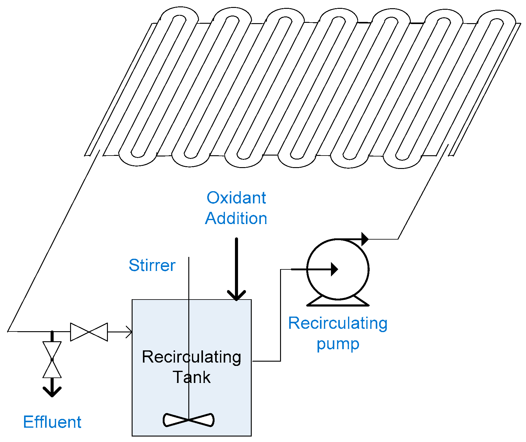
2.2. Concentrating Falling Film Reactor

A concentrating falling film reactor consists of heliostats (large rotating mirrors) that are used to concentrate solar radiation on a vertical falling film of water. Pacheco and Tyner used large tracking heliostats to concentrate solar radiation on a vertical aluminum panel (3.5 m × 1 m). The aluminum panel was mounted on a tower 37 m above the ground. Used heliostats had a total aperture area of 750 m2. Three hundred eighty liters of water were treated at a flow rate of 17 L/min resulting in a thin film thickness of 3 mm. The experiments were conducted at two concentrating levels, 30 and 60, by increasing number of heliostats focused on the falling film reactor. A cooler was required to remove excess heat energy before recirculation [67]. Use of concentrating thin films for photocatalytic treatment of water was not reported by any other researchers. This may be attributed to the complexity of system set-up. Concentrating falling film reactors, similar to PTRs, have the demerits of requiring huge area for light harvesting, reaction solution overheating, high capital cost for solar tracking devices and high operational cost for water cooling.

2.3. Compound Parabolic Concentrator

Compound Parabolic Concentrator (CPC) reactors are static reactors that consist of transparent pipes mounted on a reflector. The reflector has the shape of two half parabolas intersecting beneath each tube, this shape allows any incident light to be concentrated on transparent pipe without need for sun tracking systems. CPCs use direct as well as diffuse solar radiation while exhibiting a small concentration factor (<1.2) [88].
A demonstration plant using CPC reactors was erected in HIDROCEN, Madrid. The plant is fully automated plant for treatment of 1000 L of water. The plant consists of two rows of 21 CPC collectors connected in series having a total aperture area of 100 m2. Each collector is 1.5 m × 1.5 m, encompassing 16 parallel glass tubes of 29.2 mm inner diameter (ID). The collector reflector is made of anodized aluminum. The plant was operated in a recirculating batch mode. After treatment, pH was adjusted in sedimentation tank to enhance TiO2 agglomeration into bigger particles for quick settling. Supernatant from sedimentation tank containing <7 mg/L TiO2 was passed through a microfiltration system for final catalyst removal [73].
Treatment performance of the demonstration plant and the larger pilot plant (LPP) in Platforma Solar de Almeria (PSA), Almeria, Spain, were compared using cyanide. LPP has a total plant volume of 247 L, and an aperture area of 8.9 m2. In total, 0.2 g/L slurry TiO2 was used to degrade aqueous cyanide solution having an initial concentration of 50 mg/L. Complete degradation of Cyanide could be achieved in LPP after a normalized illumination time (t30W) of 1.5 h. Only 76% degradation could be achieved in the demonstration plant after t30W of two hours [54]. Lower treatment efficiency achieved by the demonstration plant was partially attributed to difference of water matrix. LPP used distilled water while demonstration plant used tap water. Presence of carbonates that are hydroxyl radical scavengers leads to tapering off photocatalytic degradation rates [83]. Another reason was low O2 concentration and uneven O2 distribution in the demonstration plant. O2 injection was carried directly in reactor pipes of the demonstration plant using an injection system, while, for the LPP, oxygenation was carried out in the recirculation tank [54].
CPCs are closed reactors that require continuous supply of oxygen to the reaction solution by purging of the reaction solution with oxygen/air or use of oxidants. Experiments studying treatment of synthetic sewage water were conducted in the small pilot plant in PSA. For an accumulation energy of 50 KJ/L, corresponding to six hours of illumination, dissolved organic carbon (DOC) was decreased by only 18% when using 0.2 g/L TiO2 alone. For the same accumulated energy and experimental conditions, degradation increased to 51% when adding 2 g/L H2O2. When using 4.3 g/L Sodium Persulfate, degradation further increased to 75% [89].
Packed CPC in which TiO2 is immobilized on a support eliminates the need for expensive post-separation. A packed CPC composed of five Pyrex tubes (1.9 m length and 22.2 mm outer diameter (OD)) connected in series was used for treating 21 L of aqueous triclosan solution. The tubes were packed with TiO2 immobilized on volcanic porous stones. Stones having an average size of 1 cm were coated using sol-gel method followed by sintering for three hours at 605 °C. Locally available porous stones serve as a cheap catalyst support, however the stones size should be optimized to avoid high pressure drop across the reactor and associated excessive pumping cost [90].
SOLWATER reactor is another packed CPC reactor. The reactor is composed of four tubes mounted on a CPC collector. The first two tubes contain TiO2 immobilized on Ahlstrom paper. The other two tubes contain supported photosensitizer. The water to be treated runs in series through the four pipes. Field tests were carried in Los Pereyra, Tucumán, Argentina to disinfect groundwater from shallow aquifer for use as drinking water. Groundwater was contaminated by fecal coliforms, Enterococcus faecalis and Pseudomonas aeruginosa, which is a chlorine resistant pathogen. The reactor was operated in a recirculating batch mode and treated 20 L. A 20 cm free fall of water returning to the feed tank was allowed for water oxygenation. The reactor efficiently removed fecal coliforms and Enterococcus faecalis while removal of Pseudomonas aeruginosa was not achieved. For fecal coliforms, total disinfection of groundwater contaminated with 6.6 × 10⁵ CFU/100 mL fecal coliforms could be achieved in six hours during cloudy days with a maximum UV-A intensity of 30 W/m2 [91]. After three months of operation, removal efficiency decreased. One to three percent of bacteria were still cultivable at the end of the tests. This loss of efficiency was attributed to calcium carbonate deposition on the photocatalyst and the photosensitizer [91].
A similar finding regarding loss of TiO2 effectiveness with prolonged use was obtained when CPC packed with TiO2 immobilized on glass spheres was used for degradation of emerging contaminants spiked in secondary treated wastewater effluent. Researchers found that hydroxybiphenyl, triclosan, progesterone, ibuprofen, diclofenac, ofloxacin, acetaminophen and caffeine could be degraded within t30W of one hour. After five cycles of treatment, a prolonged treatment duration was required. Contaminants were degraded in t30W of 1.5 h [92].
Loss of efficiency due to clogging of packed CPC and catalyst fouling is an operational concern. Platinized titanium dioxide immobilized on silica gel was packed in M-7 plastic tube of ID 12.7 mm and length of 2 m. The reactor was used to treat groundwater spiked with BTEX in a single pass mode. Reactor efficiency decreased significantly after two days of operation when treating extracted groundwater. A filter (0.35 microns) and an anionic/cationic ion exchange resin were used as a pretreatment for well water. Reactor receiving the pretreated water worked efficiently continuously during daytime for 25 days [93]. Problem of catalyst fouling was also encountered when using a Tubular reactor packed with TiO2 immobilized on silica beads for city water treatment. After one month of operation, red iron deposits fouled the catalyst impairing the treatment efficiency [52].
CPC has the merits of maintaining a turbulent flow that guarantees good mixing and negligible mass transfer. They use both direct and diffuse radiations [62]. However, CPC suffer from optical losses due to UV absorbance by the tube and the reflector material [87]. Another aspect is glass tubes aging known as UV-solarization. Long exposure to solar radiation lead to further reduction of tubes UV transmittance [86] impairing treatment efficiency and incurring additional costs for tubes regular replacement. One of the CPC limitations is the need for oxygen injection or alternatively adding oxidants to act as electron scavengers as well. In the case of using supported catalyst, problems of reactor clogging, and catalyst fouling are operational concerns. The demonstration plant in PSA using slurry TiO2 for treating just 1000 L of water was encompassed of 672 pipes, each having a length of 1.5 m. If supported catalyst were to be used, the ease of operation regarding regular inspection and replacement of supported catalyst is questionable. Pressure drop and high pumping cost are operational concern as well. Slurry CPC system operating in a recirculating batch mode is illustrated in Figure 2.

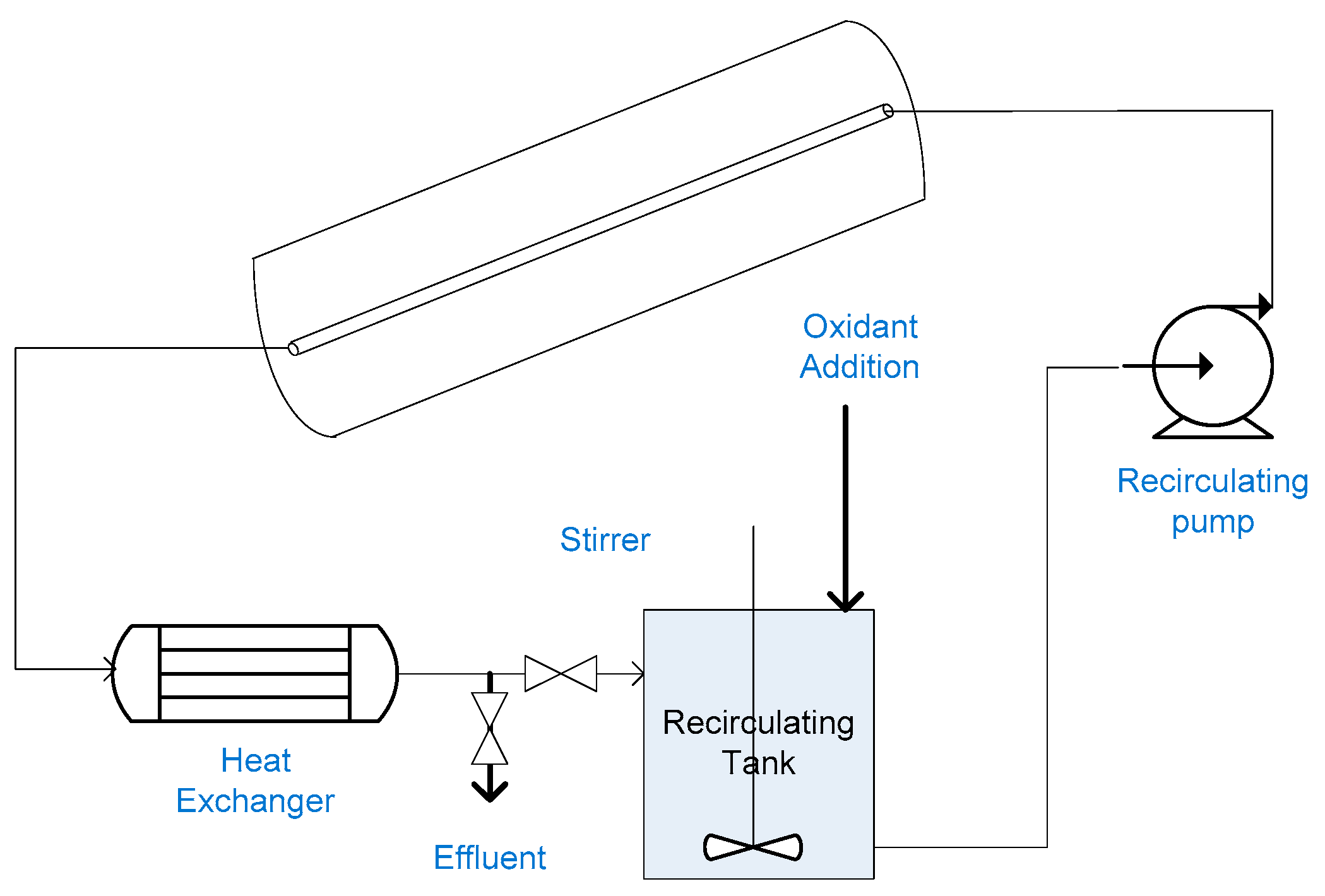
2.4. Tubular Reactor

Tubular reactor is a non-concentrating reactor in which water flows through transparent pipes. The pipes can be connected between an inlet and outlet header [94] or directly folded in a coil shaped pattern [95]. Tubular reactors are a variation of CPC. The difference is absence of reflector, which allows CPC to have a small concentrating factor. A field-test facility based on tubular photoreactors was used to treat groundwater spiked with BTEX at Tyndall Air Force Base, Florida. Experiments were conducted in a recirculating batch mode using five photoreactors connected in series. Each photoreactor contained 132 tubes (6.4 mm ID). The tubes were made of a UV transparent material and had a length of 2.4 m. The reactors had an aperture area of 10 m2 and gross area of 37.2 m2. Groundwater was filtered through 0.5 microns filter. Five hundred thirty liters of filtered groundwater were recirculated with TiO2 slurry with a high flow rate maintaining a turbulent flow. BTEX destruction using TiO2 only with no oxidant was limited [94]. Adding 100 mg/L H2O2, 75% destruction of BTEX was achieved in three hours [70]. Recently, a tubular pilot plant has been used to treat 15 L of water contaminated with nitrophenol, naphthalene, and dibenzothiophene, which are typical oil industry pollutants using slurry TiO2 [95]. Tubular reactors share the operational merits and demerits of compound parabolic concentrators.

2.5. Shallow Pond Reactor

Shallow pond reactor is a non-concentrating reactor utilizing both direct and diffuse radiations, thus operating in sunny as well as cloudy and overcast days. A solar pond fabricated from plywood and lined with polyethylene sheets was used for degradation of chlorophenol in tap water. Solar pond (106.5 cm × 53.3 cm) had a surface area of 0.57 m2, and depth of 5 cm. The pond worked in a recirculating batch mode employing slurry TiO2. Strong mixing was achieved using a recirculating pump and a submerged spray bar. After treatment was ended, the mixing facility was stopped and TiO2 settled to the pond bottom. Treated effluent was decanted from the pond surface [96]. However, the researchers did not evaluate TiO2 content of treated effluent.
Chlorophenol solution was treated using 3 g/L TiO2. Eighty-eight percent degradation was achieved in two hours, under an average UV intensity of 31.4 W/m2. A test was done using two identical ponds of 5 cm depth; one of the ponds was equipped with bubbler wands for air sparging. Pollutant concentration with time in the two ponds were almost identical indicating that dissolved oxygen in the 5 cm ponds were sufficient. When pond depth was increased to 10 and 15 cm, degradation efficiency decreased to 60% and 48%, respectively [96]. This can be attributed to limited solar radiation penetration or insufficient dissolved oxygen.
A fluidized bed photoreactor using TiO2 coated on floating ceramic spheres was used for treating distilled water spiked with phenol. The photoreactor was rectangular (15 cm × 25 cm). When treating one liter, the reactor had a depth of 2.66 cm, and can be viewed as a shallow pond reactor employing TiO2 immobilized on floating spheres. The reactor was aerated using air diffusers and illuminated using black light lamps. Light intensity at water surface was 30 W/m2. The ceramic spheres had a density of 1 g/cm3 so that they are easily suspended in water. The spheres were 0.7 mm in diameter so that they can be easily removed after treatment. Sol gel was used for TiO2 immobilization on the spheres by dip coating followed by drying and sintering at 600 °C for five hours. However, the researchers did not specify TiO2 loading on the spheres. Although the researchers did not quantitatively evaluate the stability of immobilized TiO2 on spheres, they noted that water remained transparent during treatment. The reactor operated in a batch mode. Using a catalyst loading of 8%, 10 mg/L of Phenol were degraded in 12 h while degradation byproducts were mineralized in 20 h [97].
Another photocatalytic reactor for treating of 1350 L was mounted in a mobile container to be easily transferred to sources of polluted water. The reactor tank had an operating volume of 0.06 m3 and an area of 1.8 m2. The water depth in the reactor was 3.3 cm and can be viewed as a shallow tank reactor. The system was equipped with an impeller pump for water recirculation. The 1500 L recirculation tank was aerated through an air diffuser using an air compressor. The reactor was illuminated by a 6 kW mercury lamp giving a UV intensity of 330 W/m2, which is a very high UV flux. Most researchers agree that reaction rate is proportional to the radiant flux (φ). At UV flux higher than 50 W/m2, reaction rate becomes proportional to φ0.5 [62]. Loss of photonic efficiency is due to the fact that at higher UV flux, rate of electron/hole recombination is higher.
The photoreactor worked in a recirculating batch mode for treatment of phenol solution with a concentration of 25 mg/L. Commercial photospheres-40 were used as photocatalyst. Photospheres-40 are hollow microspheres of silica coated with TiO2, having an average particle size of 45 microns, and a low density (0.22 g/cm3) that make them float on water surface. Photospheres were completely destroyed after three cycles of treatment as the fragile floating spheres did not withstand vigorous mixing and flow through the pump impeller [74].
In addition, the researchers tested degradation efficiency using TiO2 immobilized on a steel mesh. A mixture of TiO2 and a white titanium photocatalytic paint was applied on steel mesh. Additional TiO2 was added to the wet surface. The reactor bottom was also painted using the same procedure. However, organic materials wash out from the painting was encountered when using the coated steel mesh. The researchers tested degradation efficiency using TiO2 immobilized on commercial fiberglass cloth as well. TiO2 was immobilized by immersion of the filter glass cloth in TiO2 ethanol suspension and then drying at 80 °C [74]. The researchers did not report TiO2 stability on the fiberglass cloth as well. Although slurry deposition is simple, produced TiO2 coatings lack sufficient mechanical integrity and are prone to rapid attrition [98].
Shallow ponds has the potential for treatment of industrial wastewater especially in industries that already use holding ponds including pulp and paper, pharmaceuticals and textiles [57]. Sparging the pond/tank with air might not be needed given that pond/tank depth does not limit a continuous oxygen supply from atmosphere and light penetration. However, finding an efficient immobilized catalyst is still needed. Shallow pond systems working in a batch mode are illustrated in Figure 3.

2.6. Double-Skin Sheet Reactor

Double-skin sheet reactor (DSSR) is a non-concentrating reactor made of commercially available Plexiglas double skin sheet that is modified by milling the connecting straps at alternating ends and sealing the sheets sides by Plexiglas [99]. Plexiglas transmits all light above 320 nm. DSSR uses Slurry TiO2. High flow rate guarantee a turbulent flow that overcomes mass transfer limitations between TiO2 and pollutants. Since DSSR is a closed reactor, purging reaction solution with air is required.
A pilot plant consisting of 12 DSSRs (2.45 m × 0.94 m) having a total surface area of 27.6 m2 was constructed in Volkswagen plant in Wolfsburg to treat 500 L/day biologically pretreated wastewater employing 5 g/L TiO2 [72]. Pretreated wastewater was passed over a filter, then to reservoir that contained TiO2 suspension. The pilot plant worked in a recirculating batch mode. When treatment ended, TiO2 was allowed to settle down in the reservoir, then supernatant was filtered. Forty percent reduction of TOC could be achieved under an average UV solar intensity of 13.3 W/m2 in 5.5 h [100].
DSSRs have the merits of using direct and diffuse radiation, maintaining a turbulent flow regime. However they can only be operated in a slurry mode. They suffer from low optical efficiency and bubble entrapment [87]. They need purging of reaction solution with oxygen or addition of oxidants [88].

2.7. Flat Plate Reactor

Flat plate reactor is an inclined rectangular flat plate covered with a thin UV transmissive glazing. The reactor is closed preventing contact between water to be treated and ambient air [87].
An outdoor flat plate reactor made of a stainless steel flat back plate (243.8 cm × 111.8 cm, 2.73 m2 aperture area) was used for treating 57 L of aqueous solution of 4-Chlorophenol. The back plate was covered by a woven fiberglass mesh to damp out surface waves and even out flow. The reactor had a thin film glazing made of fluoropolymer that is 90% UV transmissive. Water to be treated was evenly distributed from a spray bar at the reactor top. Water was drained from the reactor by gravity through two drain holes. The reactor worked in a recirculating batch mode.
About 60% degradation of Chlorophenol was achieved after 2.5 h under sunny conditions using slurry TiO2 having a concentration of 1 g/L. When TiO2 was immobilized on fiberglass mesh, degradation efficiency was lower. Although Fiberglass mesh is not an expensive support for TiO2, catalyst loading on the mesh and the immobilization technique efficiency in terms of TiO2 content of treated effluent need to be evaluated. Recently, a reverse flow flat plate reactor employing slurry TiO2 was used for the degradation of pyrimethanil which is the active compound found in fungicides used in agriculture [101].
Flat plate reactors are characterized by a laminar flow [102]. At higher flow rates, water film thickness is increased limiting solar radiation penetration required to activate photocatalyst thus degradation efficiency decreases [103]. Enclosing the flat plate reactor with a UV transparent material is a limitation against scale-up and commercialization as well. For covering large scale flat surfaces, cost of UV transmissive glazing will significantly add to reactor cost. Glazing need to be thick to withstand pressures, increasing the thickness will decreases UV transmisivity. Additional support may be required [57] increasing construction complexity and reactor cost. Filming of the glazing from inside and outside will decrease UV transmisivity into the reactor thus decreasing its optical efficiency. Regular cleaning of the glazing from inside and outside is an operational concern.

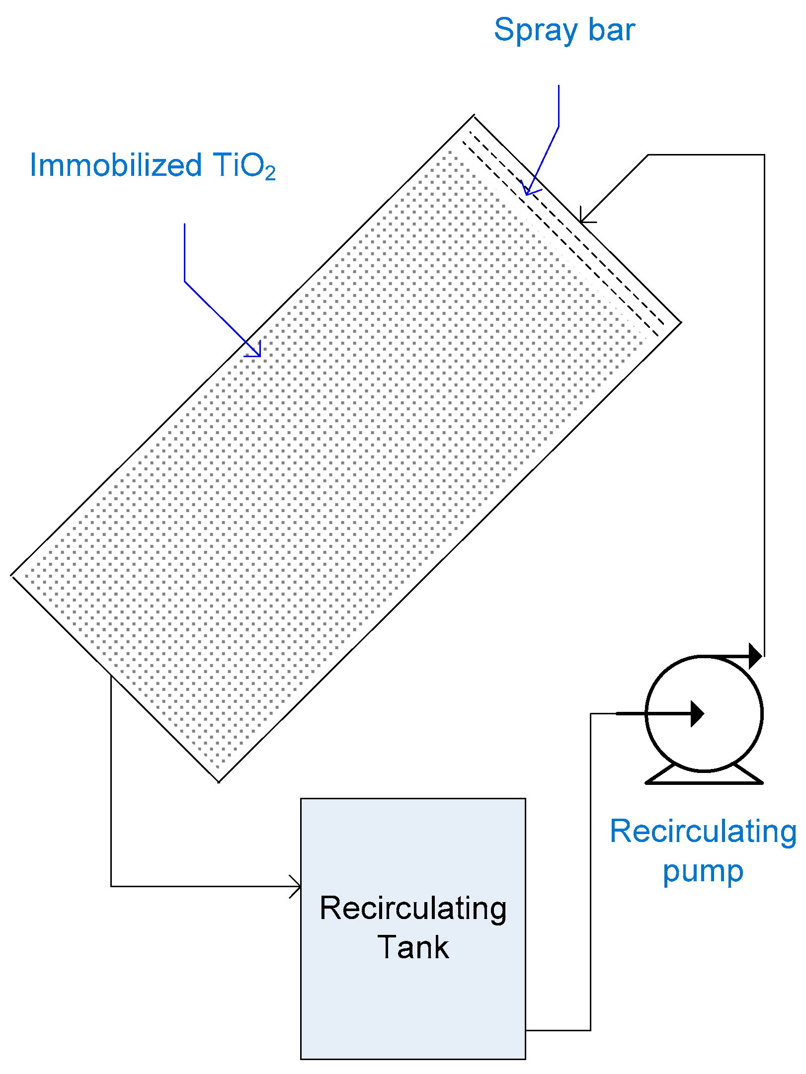
2.8. Falling Film Photoreactor

Falling film reactor is a variation of the flat plate collector where the surface of reactor is left open to the atmosphere [60]. Falling film reactor is a non-concentrating reactor employing both direct and diffuse solar radiations. Laminar flow conditions prevail resulting in film thickness of 1 mm [63]. Eliminating reactor cover has two advantages: (1) Purging reaction solution with air/oxygen is unnecessary since oxygen is exchanged rapidly between air and water [61]; (2) Falling film reactors have higher optical efficiency, elimination of transmissive losses due to cover material and thickness [60]. Thin-film fixed-bed reactor (TFFBRs) is a falling film reactor having TiO2 immobilized on the reactor surface.
Diluted pretreated leachate of Goslar landfill, Germany, was treated using TFFBR. TFFBR was made of glass plate having an area of 0.7 m2 (60 cm × 118 cm). TiO2 was immobilized on the glass plate. UV-A lamps having a maximum intensity of 100 W/m2 were used for illumination. Wastewater was dispersed over the top of the coated plate via a multichannel peristaltic pump. In a single pass experiment, 52% reduction of TOC and 56% reduction of COD were achieved at a flow rate of 1.5 L/h [104].
A TFFBR pilot plant was constructed in a textile factory in Menzel Temime, Tunisia. The pilot plant had two concrete reactors, each having a width of 2.5 m and a length of 10 m, resulting in a total illuminated area of 50 m2. Each reactor was connected to a 1000 L tank from which water is pumped to a distributor at the top of the reactor [71]. One of the pilot plant reactors was used for destruction of two commercial textile azo dyes in well water using immobilized TiO2. A painting roll was used to apply TiO2 suspension in water as a coat to the reactor surface. The researchers reported that some of the photocatalyst was stripped off under the employed experimental conditions [103]. Coatings resistance to abrasion and attrition is highly questionable using this primitive immobilization technique. The reactor was operated in a recirculating batch mode to treat 730 L having a TOC of 44.8 mg/L. forty-seven percent degradation of TOC was achieved in 8 h [103].
Falling film reactors suffer during strong winds from problem of losing of homogeneity of the falling film [32]. Catalyst film on TFFBR is exposed to pollution agents [87]. During cross winds, parts of the catalyst film are dry too impairing the treatment efficiency [105]. Another profound limitation is difficulty of immobilizing TiO2 on large flat surfaces without stripping off the photocatalyst by the water flow. Falling film reactor with immobilized TiO2 working in a recirculating batch mode is illustrated in Figure 4.

2.9. Thin Film Cascade Photoreactor

Laminar flow conditions associated with thin film flow pattern result in mass transfer limitations between the pollutants and photocatalyst resulting in a limited treatment efficiency [87]. Waterfall effect of the cascade photoreactor offer turbulence that reduce mass transfer limitations and enhance oxygen transfer [106].
When three plates thin film cascade reactor was used for degradation of an aqueous solution of benzoic acid, slightly higher degradation was achieved than when using flat plate reactor. Final dissolved oxygen concentration was also higher suggesting that better degradation results could be achieved with a cascade reactor having an increased number of steps [107]. A pilot scale thin film cascade reactor consisting of nine stainless steel plates (17.5 cm × 28 cm each) was developed. The plates were coated with TiO2 using electrophoretic method resulting in a catalyst loading of 0.89 mg/cm2 [106]. Electrophoretic deposition method requires plates degreasing, and then etching with nitric acid. An electrolytic cell equipped with a magnetic stirrer is used for TiO2 deposition. Plates are then dried and annealed in an oven at 200 °C for 90 min [107]. The reactor worked in a recirculating batch mode to treat benzoic acid in deionized water using sunlight. Similar to falling film reactor, thickness of thin film is approximately 1 mm. Seven liters of water having a 100 mg/L benzoic acid were treated at an average UV-A intensity of 17.4 W/m2. Thirty percent reduction of was achieved after three hours [106].
Although immobilization of TiO2 on plates eliminated necessity of a post-separation step of TiO2 out of treated effluent, the researchers did not evaluate coat resistance to abrasion and attrition nor did they clarify why the coated plates needed to be washed with deionized water for 15 min after each treatment cycle. Plates encountering filming and deposition problems might be an operational concern.

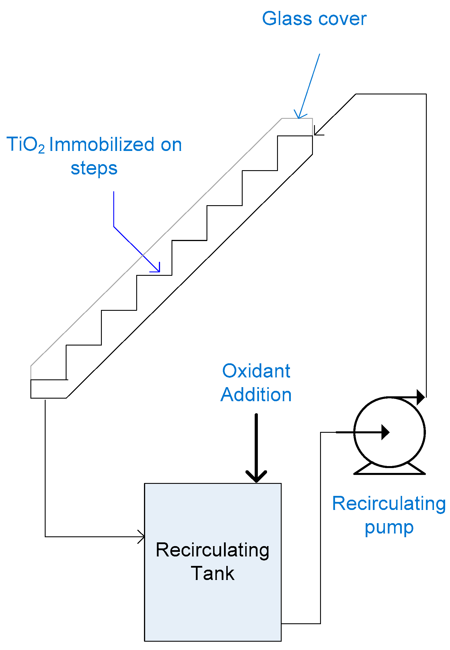
2.10. Step Photoreactor

Step photoreactor is based on cascade thin-film principal. It is a stainless steel staircase (2 m × 0.5 m) having 21 steps, covered with a Pyrex glass sheet. TiO2 is deposited on a flexible support of Ahlstrom paper using a silica-based inorganic binder. The coating method is patented. It is based on impregnation of Ahlstrom paper in a mixture of TiO2 and silica binder, and then the paper is pressed by cylindrical rolls under constant speed and pressure [108]. However, the researchers did not report TiO2 loading on Ahlstrom paper nor coating stability. The reactor was operated in a recirculating batch mode, treating 25 L. The photoreactor was used for treating an aqueous mixture of pesticides having an initial TOC concentration of 8 mg/L. Eighty percent degradation was achieved in 4.5 h under an average UV-A intensity of 30 W/m2 [108].
The researchers did not report dissolved oxygen levels throughout their experiment. Since step reactor is a closed reactor, initial dissolved oxygen in water might not be sufficient to complete the reaction and additional air sparging would be required.
Another concern is that the silica binder surface is negatively charged as silica has a point of zero charge close to 2 in contrast to TiO2, which has a neutral point of zero charge. This hinders adsorption of anionic pollutants leading to a decrease in their photo-degradation efficiency [108]. Although using this supported TiO2 eliminates post-separation process, it deprive TiO2 photocatalysis from the merit of being non-selective degrading various organic contaminants.
Similar to flat plate reactors enclosing of large scale reactor with a UV transparent material is a limitation against scale-up and commercialization due to increased capital cost associated with cover material, filming problems that would decrease reactor efficiency, increased operational cost associated with need for reaction solution purging with oxygen or oxidants addition as well as regular cleaning requirements. Step reactor with immobilized TiO2 working in a recirculating batch mode is illustrated in Figure 5.

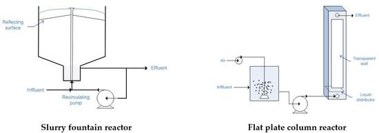
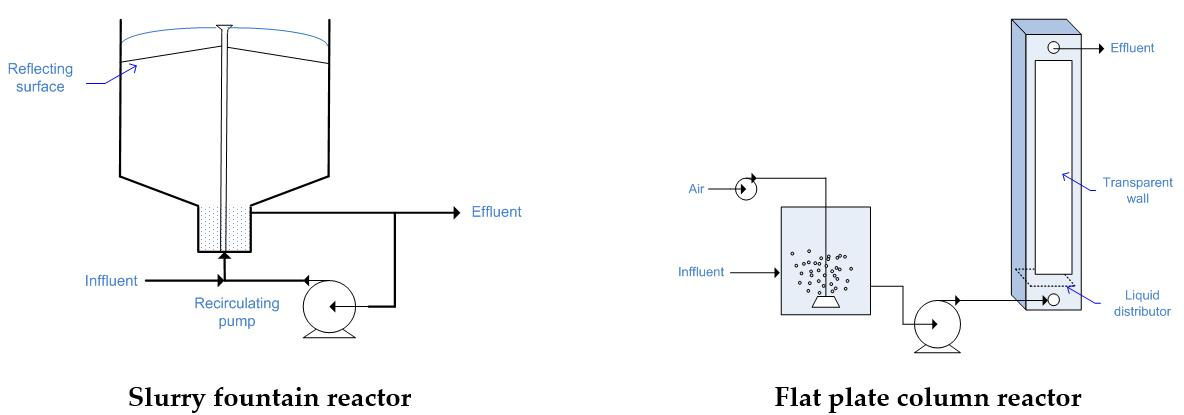
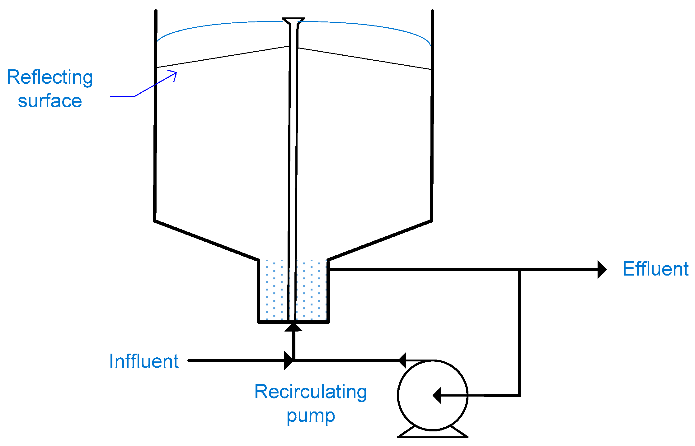
2.11. Fountain Photocatalytic Reactor

Shama et al. developed a water bell photocatalytic reactor in which water pass through a nozzle forming a water bell that flows around a vertical UV-lamp [109]. Water generated as an unsupported thin film offer two advantages: (1) a high oxygen exchange rate between air and water thus eliminating the need for additional aeration system; and (2) light penetration for excitation of the photocatalyst, thus allowing use of higher catalyst loading [110]. The water bell reactor was modified by Puma and Yue to use an external UV light source or sunlight, as illustrated in Figure 6. The fountain photocatalytic reactor is a slurry type reactor in which a thin film of polluted water containing dispersed TiO2 is continuously generated by pumping water through a specially designed nozzle [111]. Use of a reflecting surface mounted beneath the lower side of the fountain allows the water thin film to be irradiated from both sides. Fountain photoreactor was operated in a continuous mode with very high recycle ratios, almost all the water was recirculated through the nozzle with a minimum effluent flow rate. The photoreactor was used for degradation of 20 mg/L salicylic acid in deionized water using UV-A intensity of 68.5 W/m2. Degradation attained using 1 g/L of TiO2 was 21% for feed flow rate of 0.2 L/min and an irradiated diameter of 0.9 m [112]. Treated effluent was directed to a settling tank for TiO2 recovery. However, this is not efficient, since 10% of photocatalyst is lost each run [57].
Although the reactor has been further developed since 2000, it has not been further tested by other researchers. Thin film configuration allows light penetration to activate photocatalyst and provide a continuous oxygen supply. Recirculation of the reaction solution allow for good mixing and efficient mass transfer while avoiding treatment dead zones. Fountain reactor works on a continuous mode however using TiO2 in the slurry form is still an operational concern.

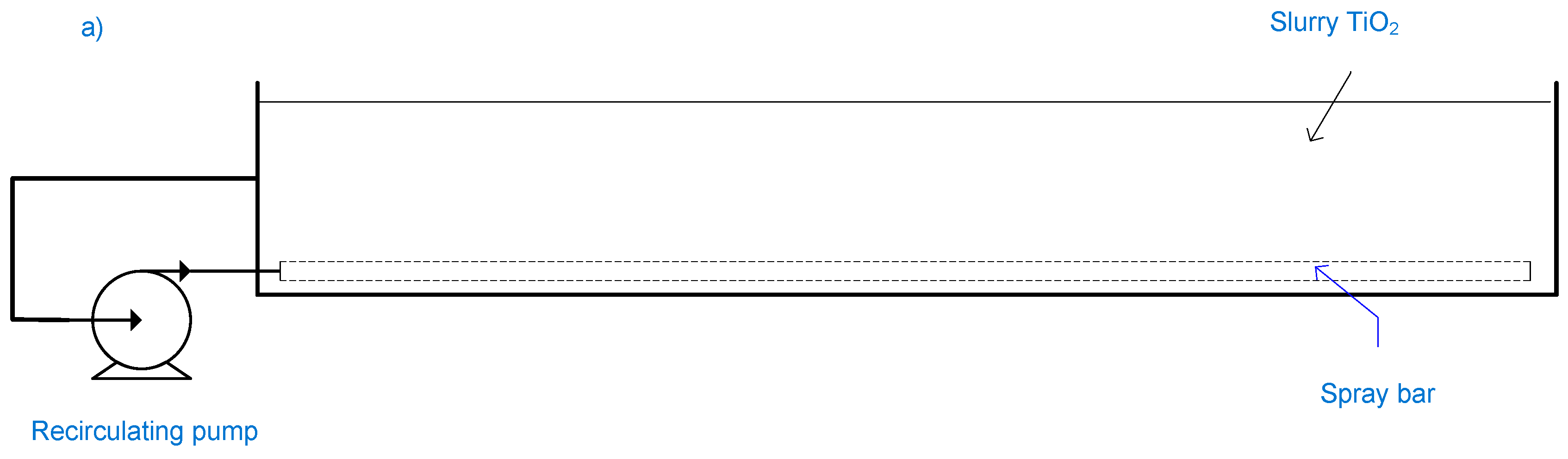
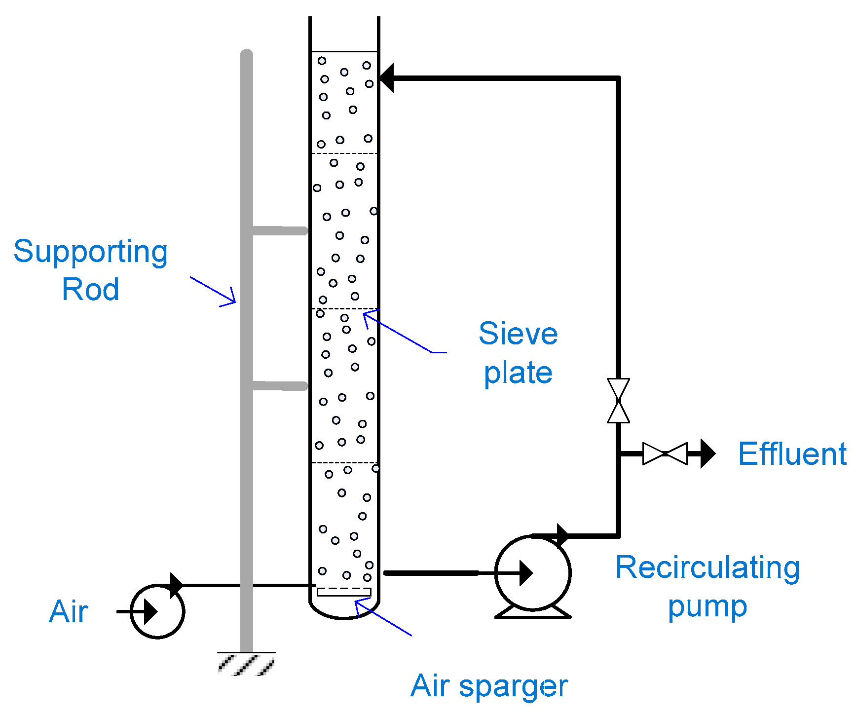
2.12. Slurry Bubble Column Reactor

Kamble et al. used a slurry bubble column reactor composed of a borosilicate glass column of 10 cm ID and 3 m length, and supported by steel rods [113]. Water to be treated entered the column at the top while air was supplied to reaction medium from column bottom. Sieve plates were used to reduce backmixing throughout the column. A parabolic reflector of a total surface area of 6 m2 was used to concentrate solar radiation on the reactor. The collector position was changed every 15 min to continuously track the sun. TiO2 was separated from treated water via a candle filter placed before the effluent outlet.
The photoreactor worked in a recirculating batch mode treating 19.5 L. Aqueous solutions of nitrobenzene, chlorobenzene and phenol were treated using slurry TiO2 with concentrations of 3, 0.15 and 2 g/L respectively. In each case, the pollutant initial concentration was 100 mg/L. After four hours, degradation achieved for nitrobenzene and chlorobenzene were 70% and 96%, respectively. Only 25% degradation of phenol was achieved in six hours [113].
The photoreactor performance was higher when using a low TiO2 concentration. When using 1 g/L TiO2 in a parabolic trough collector, transmittance drops in the reactor pipes to zero over a 1 cm path length [54]. In this 10 cm column, increased suspension opacity caused a screening effect that reduced the system efficiency.
A schematic drawing of a non-concentrating slurry bubble column photoreactor is illustrated in Figure 7. The concept of slurry bubble column reactor is not attractive for scale-up and commercialization for the following reasons: (1) presence of moving solar tracking parts in case of a concentrating column add to investment and operation costs; and (2) reactors with transparent walls for radiation transmittance experience problems of filming and are prone to breakage risks, loss of UV transmittance and aging due to long exposure to sunlight.

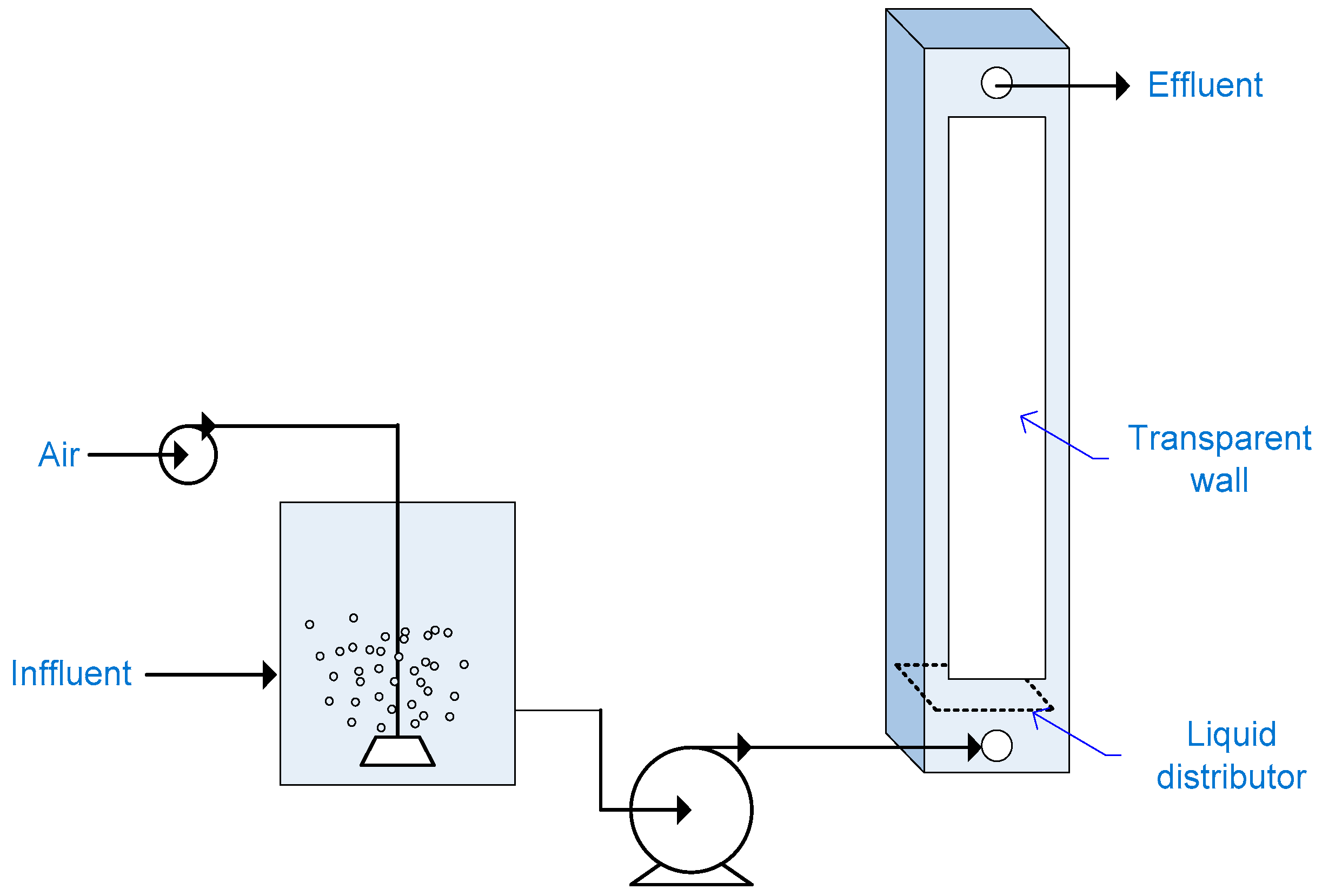
2.13. Flat Plate Column Reactor

Designing a photoreactor must take into account the hydrodynamic field, radiation source and field, mass balance and reaction kinetics [114]. Vaiano et al. used CFD model in conjunction with Helmholtz equation for predicting the light distribution to design a reactor having a flat plate geometry [115]. The resultant reactor had a width of 5 cm, thickness of 2.5 cm and height of 30 cm. The reactor walls along the width are transparent. The reactor is packed with N-doped TiO2 immobilized on glass spheres. Influent is being aerated then pumped to the column bottom through a liquid distributor for a homogeneous liquid flow through the packing material. The reactor has been tested for degrading an aqueous solution of methylene blue (10 mg/L). Sixty-five percent degradation was achieved after 6.5 h using visible light, while degradation reached 90% when using UV light [115].
A schematic drawing for a flat plate column reactor is illustrated in Figure 8. Since the reactor is closed, aeration or addition of oxidants is a must. For scaling up purposes, channeling can be avoided through using multiple liquid distributors throughout the column however pressure drop across the column associated with excessive pumping cost will still be a concern.

2.14. Pebble Bed Photoreactor

The Pebble photocatalytic reactor was used for treatment of water containing dyes simulating textiles dye house effluent. The reactor composed of a trough (52 cm × 45 cm) made of Perspex transparent sheet. White pebbles having a mean diameter of 9 mm were fixed on the trough surface using two epoxy adhesives [81]. TiO2 was immobilized on the pretreated pebbles surface by spraying of a 2% TiO2 ethanol suspension followed by drying at 70 °C. Five coating cycles were conducted to obtain an adequate TiO2 coating. The coated pebbles were dried at 150 °C for eight hours [116]. The stability of the immobilized TiO2 is questionable since only drying was performed while firing of the coated pebbles at high temperatures is normally practiced to enhance TiO2 coat adherence to the support [39,41,42,117].
The photoreactor worked in a recirculating batch mode treating ten liters of water having an initial TOC concentration of 83 mg/L. Fifteen percent TOC reduction was achieved in 5 h [81]. Similar to all reactors characterized by a laminar flow, pebble bed reactor experiences limited degradation efficiency. Epoxy resins have limited UV resistance, which raise an operational concern regarding the pebbles stability on the trough.

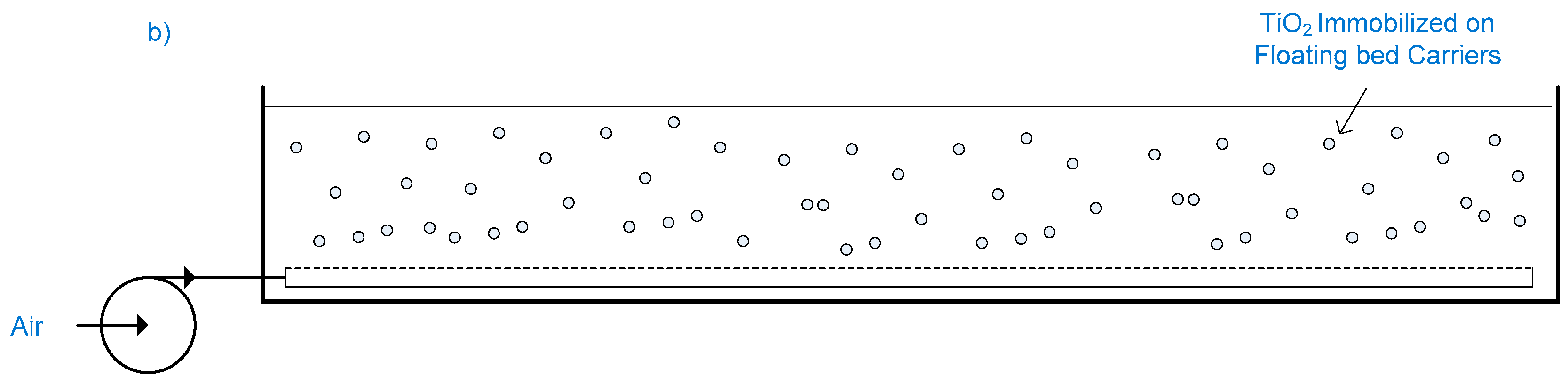
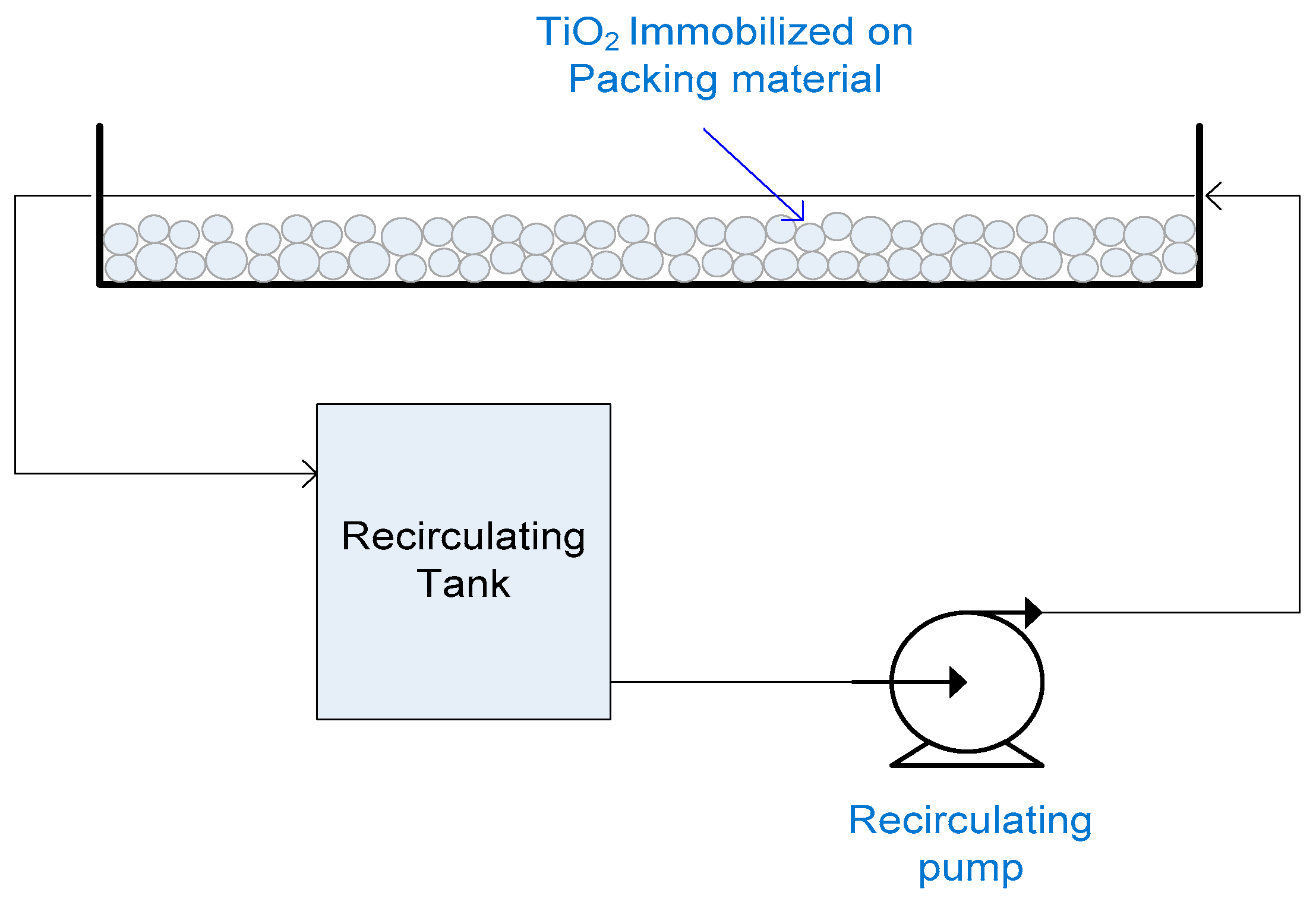
2.15. Flat Packed Bed Reactor

TiO2 immobilized on sand was used as a photocatalyst in the photoreactor. The photoreactor had a packed bed of 40 grams sand, length of 35 cm and width of 2 cm. Using naturally occurring sand as a support enables the production of a cheap photocatalyst. TiO2 was immobilized on quartz sand with average grain size of 250 microns using sol gel method, followed by calcination at 850 °C. Although unsupported anatase generally transform to rutile at temperatures around 600 °C [118], the researchers reported that diffusion of Si from sand onto TiO2 coating restricted the atomic rearrangement leading to stabilization of the anatase phase. The photoreactor operated in a recirculating batch mode. One liter of deionized water inoculated with E-Coli, was recirculated through the photoreactor. At a UV intensity 3.7 W/m2, complete sterilization was not achieved after 100 min. Poor performance was attributed to limited catalyst exposure to light since only the top layer of grains were exposed to light [119]. Packed bed reactor working in a recirculating batch mode is illustrated in Figure 9.

3. Comparison of Different Reactors Throughput

Table 2 presents throughputs of different slurry reactors and their degradation efficiencies achieved during selected treatment trials. Throughputs of reactors employing immobilized TiO2 and their degradation efficiencies are presented in Table 3. All the selected treatment trials were conducted using solar light or UV-A light simulating solar light at neutral pH without chemical oxidants addition. An exact comparison between all reactor configurations is not possible, since the treatment trials have different target pollutants in different concentration levels, with different water matrices. However, an insight on the throughput and efficiency that can be achieved by each reactor configuration is given.
Although PTRs could achieve high degradation efficiency for wastewater streams having a low organic content (tens milligrams per liter), throughput is low due to large light harvesting areas. Lower throughput is achieved when PTR was used for treating wastewater of relatively high COD (2000 mg/L). This reflects that advanced oxidation is considered optimum for treatment of water containing a low organic load—having a TOC lower than 100 mg/L—and a COD lower than 250 mg/L [1].
Throughputs achieved by CPC vary greatly according to the water matrix and pollutant concentration. Throughputs for CPC is calculated based on the reflector area, however these throughputs will further decrease when taking into account area left between CPC modules to prevent CPC shadowing on each other [58].
All reactors employing immobilized TiO2 and characterized by a laminar flow (thin-film fixed-bed, pebble bed, and thin film cascade reactors) experience limited degradation efficiency as well as limited throughput. Solar pond photoreactor operating in a slurry mode achieved high throughput and an acceptable degradation efficiency. Fountain reactor has shown a relatively high throughput. However, it should be taken into consideration that only 20% degradation efficiency was achieved while the system was operating in continuous flow mode. Allowing for a higher residence time will increase degradation efficiency and lower the throughput. Similarly shallow tank reactor employing immobilized TiO2 achieved the highest throughput while degradation efficiency was only 50%. A lower throughput is expected when allowing longer treatment to attain an acceptable degradation efficiency.

4. Conclusions and Future Prospects

Design of TiO2 photocatalytic reactor is not a trivial process; it involves the reaction solution, solid photocatalyst, oxygen gas stream and ultra-bandgap light. Photocatalytic reactor engineering is complicated due to the necessity of provision of adequate irradiation throughout the whole reaction volume to activate photocatalyst, uniform reactor irradiation to avoid treatment dead zones, efficient mass transfer, continuous oxygen supply to the reaction solution, and easy catalyst separation after treatment.
Degradation efficiency as a function of system throughput is a powerful indicator for comparing the performance of photocatalytic reactors of different types and geometries, at different development scales as well. PTRs have a low throughput. PTRs are expensive due to presence of moving parts and solar tracking devices. They have high operational cost associated with water cooling. PTRs are not competent for scale-up and commercialization. For the same reasons as well as the complexity of set-up, concentrating falling film reactors are not competent for scale-up either.
DSSRs have low throughput. Being closed reactors that need purging of reaction solution with oxygen or addition of oxidants, they may encounter filming problems. Operating only using slurry TiO2 render them not competent for commercialization. Flat plate reactors have a relatively low throughput. They are not competent for scale-up and commercialization since they operate in the laminar flow regime, they are closed reactors that need purging with oxygen or addition of oxidants, they require additional support for glazing, and glazing experience filming problems due to accumulation of either dust from the outer side or contaminants from the inner side leading to low optical efficiency.
Falling film reactors employing supported TiO2 have very low throughputs and limited degradation efficiency. Operating with a laminar flow, large area is required to attain an acceptable degradation efficiency. A robust affordable immobilization technique for immobilizing TiO2 on large flat surfaces without stripping off the photocatalyst needs to be developed. CPCs are the most commonly used reactor configuration for use in experimental testing and demonstration plants. This can be partially attributed to the ease of experimental set-up. CPC need purging with oxygen or addition of oxidants. They suffer from optical losses and tubes aging. For packed CPCs, they encounter problems of reactor clogging, catalyst fouling and high pumping cost that render them not competent for scale-up and commercialization.
Shallow pond and shallow tank reactors and fountain reactors have the potential of meeting all the process requirements, light penetration to activate photocatalyst, uniform reactor irradiation to avoid treatment dead zones, efficient mass transfer, continuous oxygen supply, with a reasonable reactor throughput given that easy catalyst separation after treatment is achieved through finding an efficient immobilized photocatalyst.

Acknowledgments

The authors are grateful to the American University in Cairo, office of graduate studies for the research financial support.

Author Contributions

Yasmine Abdel-Maksoud wrote the paper under the guidance and supervision of Emad Imam and Adham Ramdan.

Conflicts of Interest

The authors declare no conflict of interest.

References

  1. Comninellis, C.; Kapalka, A.; Malato, S.; Parsons, S.; Poulios, I.; Mantzavinos, D. Perspective Advanced oxidation processes for water treatment: Advances and trends for R & D. J. Chem. Technol. Biotechnol. 2008, 83, 769–776. [Google Scholar]
  2. Blake, D. Bibliography of Work on the Heterogeneous Photocatalytic Removal of Hazardous Compounds from Water and Air, Update Number 4 to October 2001, NREL/TP-510–31319; National Renewable Energy Laboratory: Golden, CO, USA, 2001. [Google Scholar]
  3. Arana, J.; Melian, J.; Rodriguez, J.; Diaz, O.; Viera, A.; Pena, J.; Sosa, P.; Jimenez, V. TiO2-photocatalysis as a tertiary treatment of naturally treated wastewater. Catal. Today 2002, 76, 279–289. [Google Scholar] [CrossRef]
  4. Al-Bastaki, N. Performance of advanced methods for treatment of wastewater: UV/TiO2, RO and UF. Chem. Eng. Process 2004, 43, 935–940. [Google Scholar] [CrossRef]
  5. Likodimos, V.; Dionysiou, D.; Falaras, P. Clean water: Water detoxification using innovative photocatalysts. Res. Environ. Sci. Biotechnol. 2010, 9, 87–94. [Google Scholar] [CrossRef]
  6. Dimitroula, H.; Daskalaki, V.; Frontistis, Z.; Kondaides, D.; Panagiotopoulou, P.; Xekoukoulotakis, N.; Mantzavinos, D. Solar photocatlysis for the abatement of emerging micro-contaminants in wastewater: Synthesis, characterization and testing of various TiO2 samples. Appl. Catal. B: Environ. 2012, 117, 283–291. [Google Scholar] [CrossRef]
  7. Miranda-Garcia, N.; Maldonado, M.; Coronado, J.; Malato, S. Degradation study of 15 emerging contaminants at low concentrationby immobilized TiO2 in a pilot plant. Catal. Today 2010, 151, 107–113. [Google Scholar] [CrossRef]
  8. Agullo-Barcelo, M.; Polo-Lopez, M.; Lucena, F.; Jofre, J.; Fernandez-Ibanez, P. Solar advanced oxidation processes as disinfection tertiary treatments for real wastewater: Implicatons for water reclamation. Appl. Catal. B: Environ. 2013, 136, 341–350. [Google Scholar] [CrossRef]
  9. Dominguez-Espindola, R.; Silva-Martinez, S.; Ortiz-Hernandez, M.; Roman-Zubillaga, J.; Guardian-Tapia, R. Photocatlytic disinfection of municipal wastewater using TiO2 film and Ag/TiO2 powder under UV and solar light irradiation. Mex. J. Sci. Res. 2013, 2, 60–68. [Google Scholar]
  10. Navalon, S.; Alvaro, M.; Garcia, H.; Escrig, D.; Costa, V. Photocatalytic water disinfection of cryptosporidium parvum and Giardia lamlia using a fibrous ceramic TiO2 photocatalyst. Water Sci. Technol. 2009, 59, 639–645. [Google Scholar] [CrossRef] [PubMed]
  11. Gamage, J.; Zhang, Z. Applications of photocatalytic disinfection. Int. J. Photoenergy 2010, 2010. [Google Scholar] [CrossRef]
  12. Maness, P.; Smolinski, S.; Blake, D.; Huang, Z.; Wolfrum, E.; Jacoby, W. Bacericidal activity of photocatalytic TiO2 reaction: Toward an understanding of its killing mechanism. Appl. Environ. Microbiol. 1999, 65, 4094–4098. [Google Scholar] [PubMed]
  13. Sokmen, M.; Degerli, S.; Aslan, A. Photocatalytic disinfection of Giardia intestinals and acanthamoeba castellani cysts in water. Exp. Parasitol. 2008, 119, 44–48. [Google Scholar] [CrossRef] [PubMed]
  14. Lee, J.; Kang, M.; Choung, S.; Ogino, K.; Miyata, S.; Kim, M.; Park, J.; Kim, J. The preparation of TiO2 nanometer photocatalyst film by a hydrothermal method and its sterilization performance for Giardia lamblia. Water Res. 2004, 38, 713–719. [Google Scholar] [CrossRef] [PubMed]
  15. Ede, S.; Hafner, L.; Dunlop, P.; Byrne, J.; Will, G. photocatalytic disinfection of bacterial pollutants using suspended and immobilized TiO2 powders. Photochem. Photobiol. 2012, 88, 728–735. [Google Scholar] [CrossRef] [PubMed]
  16. Mccullagh, C.; Robertson, J.; Bahnemann, D.; Robertson, P. The application of TiO2 photocatalysis for disinfection of water contaminated with pathogenic micro-organisms: A review. Res. Chem. Intermed. 2007, 33, 359–375. [Google Scholar] [CrossRef]
  17. Chong, M.N.; Jin, B. Photocatalytic treatment of high concentration carbamazepine in synthetic hospital wastewater. J. Hazard. Mater. 2012, 199, 135–142. [Google Scholar] [CrossRef] [PubMed]
  18. Rizzo, L.; Ferro, G.; Manaia, C. Wastewater disinfection by solar heterogeeous photocatalysis: Effect on tetracycline resistant/sensetive enterococcus strains. Glob. Nest J. 2014, 16, 457–464. [Google Scholar]
  19. Ghaly, M.Y.; Jamil, T.S.; El-Seesy, I.E.; Souaya, E.R.; Nasr, R.A. Treatment of highly polluted paper mill wastewater by solar photocatalytic oxidation with synthesized nano TiO2. Chem. Eng. J. 2011, 168, 446–454. [Google Scholar] [CrossRef]
  20. Kansal, S.; Singh, M.; Sud, D. Effluent quality at kraft/soda agro-based paper mills and its treatment using a heterogeneous photocatalytic system. Desalination 2008, 228, 183–190. [Google Scholar] [CrossRef]
  21. Amat, A.; Arques, A.; Lopez, F.; Miranda, M. Solar photo-catalysis to remove paper mill wastewater pollutants. Sol. Energy 2005, 79, 393–401. [Google Scholar] [CrossRef]
  22. Rodrigues, A.; Boroski, M.; Shimada, N.; Garcia, J.; Nozaki, J.; Hioka, N. Treatment of paper pulp and paper mill wastewater by coagulation-flocculation followed by heterogeneous photocatalysis. J. Photochem. Photobiol. A: Chem. 2008, 194, 1–10. [Google Scholar] [CrossRef]
  23. Banu, J.; Anandan, S.; Kaliappan, S.; Yeom, I. Treatment of dairy wastewater using anaerobic and solar photocatalytic methods. Sol. Energy 2008, 82, 812–819. [Google Scholar] [CrossRef]
  24. Pekakis, P.; Xekoukoulotakis, N.; Mantzavinos, D. Treatment of textile dyehouse wastewater by TiO2 photocatalysis. Water Res. 2006, 40, 1276–1286. [Google Scholar] [CrossRef] [PubMed]
  25. Saquib, M.; Tariq, M.A.; Faisal, M.; Muneer, M. Photocatalytic degradation of two selected dye derivatives in aqueous suspensions of titanium dioxide. Desalination 2008, 219, 301–311. [Google Scholar] [CrossRef]
  26. Luo, M.; Bowden, D.; Brimblecombe, P. Removal of dyes from water using a TiO2 photocatalyst supported on black sand. Water Air Soil Pollut. 2009, 198, 233–241. [Google Scholar] [CrossRef]
  27. Oliveira, D.F.M.; Batista, P.S.; Muller, P.S., Jr.; Velani, V.; Franca, M.; Souza, D.; Machado, A. Evaluating the effectiveness of photocatalysts based on Titanium dioxide in the degradation of the dye Ponceau 4R. Dyes Pigment. 2011, 92, 563–572. [Google Scholar] [CrossRef]
  28. Zayani, G.; Bousseimi, L.; Pichat, P.; Mhenni, F.; Ghrabi, A. Photocatalytic Degradation of four Textile Azo Dyes in Aqueous TiO2 Suspensions: Practical Outcomes and Revisited Pathways. J. Adv. Oxid. Technol. 2006, 9, 65–78. [Google Scholar]
  29. Kasanen, J.; Salstela, J.; Suvanto, M.; Pakkanen, T. Photocatalytic degradation of methylene blue in water solution by multilayer TiO2 coating on HDPE. Appl. Surf. Sci. 2011, 258, 1738–1743. [Google Scholar] [CrossRef]
  30. Sokmen, M.; Tatlidil, I.; Breen, C.; Clegg, F.; Buruk, C.; Sivlim, T.; Akkan, S. A new nano-TiO2 immobilized biodegradable polymer with self-cleaning properties. J. Hazard. Mater. 2011, 187, 199–205. [Google Scholar] [CrossRef] [PubMed]
  31. Toor, A.; Verma, A.; Jotshi, C.; Bajpai, P.; Singh, V. Photocatalytic degradation of direct yellow 12 dye using UV/TiO2 in a shallow pond slurry reactor. Dyes Pigment. 2006, 68, 53–60. [Google Scholar] [CrossRef]
  32. Gernjak, W.; Maldonado, M.I.; Malato, S.; Caceres, J.; Krutzler, T.; Glaser, A.; Bauer, R. Pilot-plant treatment of olive mill wastewater (OMW) by solar TiO2 photocatalysis and solar photo-Fenton. Sol. Energy 2004, 77, 567–572. [Google Scholar] [CrossRef]
  33. Nogueira, V.; Lopes, I.; Rocha-Santos, T.; Goncalves, F.; Duarte, A.; Pereira, R. Photocatalytic treatment of olive oil mill wastewater using TiO2 and Fe2O3 nanomaterials. Water Air Soil Pollut. 2016, 227. [Google Scholar] [CrossRef]
  34. Klavarioti, M.; Mantzavinos, D.; Kassinos, D. Removal of residual pharamceuticals from aqueous systems by advanced oxidation processes. Environ. Int. 2009, 35, 402–417. [Google Scholar] [CrossRef] [PubMed]
  35. Deegan, A.; Shaik, B.; Nolan, K.; Urell, K.; Oelgemoller, M.; Tobin, J.; Morrissey, A. Treatment options for wastewater effluents from pharmaceutical companies. Int. J. Environ. Sci. Technol. 2011, 8, 649–666. [Google Scholar] [CrossRef]
  36. Anheden, M.; Goswami, D.; Svedberg, G. photocatalytic treatment of wastewater from 5-Flurouracil manufacturing. Sol. Energy Eng. 1996, 118, 2–8. [Google Scholar] [CrossRef]
  37. Augugliaro, V.; Gracia-Lopez, E.; Loddo, V.; Malato, S.; Maldonado, I.; Marci, G.; Molinari, R.; Palmisano, L. Degradation of lincomycin in aqueous medium: Coupling of solar photocatalysis and membrane separation. Sol. Energy 2005, 79, 402–408. [Google Scholar] [CrossRef]
  38. Torbina, V.; Vodyankin, A.; Ivanchikova, I.; Kholdeeva, O.; Vodyankina, O. Support pretreatment effect on the catalytic properties and reusability of silica-supported Titania catalysts in 2,3,6-Trimethylphenol oxidation with Hydrogen peroxide. Kinet. Catal. 2015, 56, 369–374. [Google Scholar] [CrossRef]
  39. Tasbihi, M.; Ngah, C.; Aziz, N.; Mansor, A.; Abdullah, A.; Teong, L.; Mohamed, A. Lifetime and regeneration studies of various supported TiO2 photocatalysts for degradation of phenol under UV-C light in a batch reactor. Ind. Eng. Chem. Res. 2007, 46, 9006–9014. [Google Scholar] [CrossRef]
  40. Zainudin, N.; Abdullah, A.; Mohamed, A. Development of supported TiO2 photocatalyst based on adsorbent for photocatalytic degradation of phenol. In Proceedings of the International Conference on Environment 2008, Penang, Malaysia, 15–17 December 2008.
  41. Zulfakar, M.; Hairul, N.; Akmal, H.; Rahman, M.A. Photocatalytic degradation of phenol in a fluidized bed reactor utilizing immobilized TiO2 photocatalyst: Characterization and process studies. J. Appl. Sci. 2011, 11, 2320–2326. [Google Scholar] [CrossRef]
  42. Haarstrick, A.; Kut, O.; Heinzle, E. TiO2-assissted degradation of environmentally relevant organic compounds in wastewater using a novel fluidized bed photreactor. Environ. Sci. Technol. 1996, 30, 817–824. [Google Scholar] [CrossRef]
  43. Sivlim, T.; Akkan, S.; Altin, I.; Koc, M.; Sokmen, M. TiO2 immobilized biodegradable polymer for photocatalytic removal of chlorophenol. Water Air Soil Pollut. 2012, 223, 3955–3964. [Google Scholar] [CrossRef]
  44. Seck, E.; Dona-Rodriguez, J.; Fernandez-Rodriguez, C.; Portillo-Carrizo, D.; Hernandez-Rodriguez, M.; Gonzalez-Diaz, O.; Perez-Pena, J. Solar photocatalytic removal of herbicides from real wastewater by using sol-gel synthesized nanocrystalline TiO2: Operational parameters optimization and toxicity studies. Sol. Energy 2013, 87, 150–157. [Google Scholar] [CrossRef]
  45. Jimenez, M.; Maldonado, M.; Rodriguez, E.; Hernandez-Ramirez, A.; Saggioro, E.; Carra, I.; Perez, J. Supported TiO2 solar photocatalysis at semi-pilot scale: Degradation of pesticides found in citrus processing industry wastewater, reactivity and influence of photogenerated species. J. Chem. Technol. Biotechnol. 2015, 90, 149–157. [Google Scholar] [CrossRef]
  46. Echavia, G.; Matzusawa, F.; Negishi, N. Photocatalytic degradation of organophosphate and phosphonoglycine pesticides using TiO2 immobilized on silica gel. Chemosphere 2009, 76, 595–600. [Google Scholar] [CrossRef] [PubMed]
  47. Shavisi, Y.; Sharifnia, S.; Hosseini, S.; Khadivi, M. Application of TiO2/perlite photocatalysis for degradation of ammonia in wastewater. J. Ind. Eng. Chem. 2014, 20, 278–283. [Google Scholar] [CrossRef]
  48. Shavisi, Y.; Sharifnia, S.; Zendehzaban, M.; Mirghavami, M.; Kakehazar, S. Application of solar light for degradation of ammonia in petrochemical wastewater by a floating TiO2/LECA photocatalyst. J. Ind. Eng. Chem. 2014, 20, 2806–2813. [Google Scholar] [CrossRef]
  49. Singla, P.; Pandey, O.; Singh, K. Study of photocatalytic degradation of environmentally harmful phthalate esters using Ni-doped TiO2 nanoparticles. Int. J. Environ. Sci. Technol. 2016, 13, 849–856. [Google Scholar] [CrossRef]
  50. Czech, B. Advanced photooxidation of surfactants in wastewater. Chemik 2012, 66, 1314–1325. [Google Scholar]
  51. Alrousan, D.; Polo-Lopez, M.; Dunlop, P.; Fernandez-Ibanez, P.; Byrne, J. Solar photocatalytic disinfection of water with immobilised titanium dioxide in re-circulating flow CPC reactors. Appl. Catal. B: Environ. 2012, 128, 126–134. [Google Scholar] [CrossRef]
  52. Nakano, K.; Obuchi, E.; Takagi, S.; Yamamoto, R.; Tanizaki, T.; Taketomi, M.; Eguchi, M.; Ichida, K.; Suzuki, M.; Hashimoto, A. Photocatlytic treatment of water containing dinitrophenol and city water over TiO2/SiO2. Sep. Purif. Technol. 2004, 34, 67–72. [Google Scholar] [CrossRef]
  53. Motegh, M.; Ommen, J.; Appel, P.; Kreutzer, M. Scale-up study of a multiphase photocatalytic reactor—Degradation of Cyanide in water over TiO2. Environ. Sci. Technol. 2014, 48, 1574–1581. [Google Scholar] [CrossRef] [PubMed]
  54. Malato, S.; Blanco, J.; Vidal, A.; Fernandez, P.; Caceres, J.; Trincado, P.; Oliveira, J.; Vincent, M. New large solar photocatalytic plant: Set-up and preliminary results. Chemosphere 2002, 47, 235–240. [Google Scholar] [CrossRef]
  55. Fostier, A.; Pereira, M.; Rath, S.; Guimaraes, J. Arsenic removal from water employing heterogeneous photocatalysis with TiO2 immobilized in PET bottles. Chemosphere 2008, 72, 319–324. [Google Scholar] [CrossRef] [PubMed]
  56. Deedar, N.A.; Aslam, I. Evaluation of the adsorption potential of titanium dioxide nanoparticles for arsenic removal. J. Environ. Sci. 2009, 21, 402–408. [Google Scholar]
  57. Goswami, D. Engineering of Solar Photocatalytic Detoxification and Disinfection Processes. Adv. Sol. Energy 1995, 10, 165–210. [Google Scholar]
  58. Spasiano, D.; Marotta, R.; Malato, S.; Fernandez-Ibanez, P. Solar photocatalysis: Materials, reactors, some commercial and pre-industeralized applications. A comprehensive approach. Appl. Catal. B: Environ. 2015, 170, 90–123. [Google Scholar] [CrossRef]
  59. Lazar, M.A.; Varghese, S.; Nair, S.S. Photocatalytic water treatment by Titanium dioxide: Recent updates. Catalysts 2012, 2, 572–601. [Google Scholar] [CrossRef]
  60. Braham, R.; Harris, A. Review of Major Design and Scale-up Considerations for Solar Photocatalytic Reactors. Ind. Eng. Chem. Res. 2009, 48, 8890–8905. [Google Scholar] [CrossRef]
  61. Lee, S.; Mills, A. Detoxification of water by semiconductor photocatalysis. J. Ind. Eng. Chem. 2004, 10, 173–187. [Google Scholar]
  62. Malato, S.; Fernandez-Ibanez, P.; Maldonado, M.; Blanco, J.; Gernjak, W. Decontamination and disinfection of water by solar photocatalysis: Recent overview and trends. Catal. Today 2009, 147, 1–59. [Google Scholar] [CrossRef]
  63. Alfano, O.; Bahnemann, D.; Cassano, A.; Dillert, R.; Goslich, R. Photocatalysis in water environments using artificial and solar light. Catal. Today 2000, 58, 199–230. [Google Scholar] [CrossRef]
  64. Bahnemann, D. Photocatalytic water treatment: Solar energy applications. Sol. Energy 2004, 77, 445–459. [Google Scholar] [CrossRef]
  65. Adesina, A. Industrial exploitation of photocatalysis: Progress, perspectives and prospects. Catal. Surv. Asia 2004, 8, 265–273. [Google Scholar] [CrossRef]
  66. Blanco-Galvez, J.; Fernandez-Ibanez, P.; Malato-Rodriguez, S. Solar photocatalytic detoxification and disinfection of water: Recent overview. Sol. Energy Eng. 2007, 129, 4–15. [Google Scholar] [CrossRef]
  67. Pacheco, J.; Tyner, C. Enhancement of processes for solar photocatalytic detoxification of water. In Proceedings of the ASME Solar Energy Conference on Solar Engineering 1990, Miami, FL, USA, 1–4 April 1990; pp. 163–166.
  68. Mehos, M.; Turchi, C. Field testing solar photocatalytic detoxification on TCE-contaminated groundwater. Environ. Prog. 1993, 12, 194–199. [Google Scholar] [CrossRef]
  69. Minero, C.; pelizzeti, E.; Malato, S.; Blanco, J. Large solar plant photocatalytic water decontamination: Degradation of pentachlorophenol. Chemosphere 1993, 26, 2013–2119. [Google Scholar] [CrossRef]
  70. Goswami, D.; Klausner, J.; Mathur, G.; Martin, A.; Schanze, K.; Wyness, P.; Turchi, C.; Marchand, E. Solar photocatalytic treatment of groundwater at Tyndall AFB: Field test results. In Proceedings of the 1993 American solar energy society annual conference, Washigton, DC, USA, 1993.
  71. Bousseimi, L.; Geissen, S.; Schroeder, H. Textile wastewater treatment and reuse by solar catalysis: Results from a pilot plant in Tunisia. Water Sci. Technol. 2004, 49, 331–337. [Google Scholar]
  72. Dillert, R.; Vollmer, S.; Gross, E.; Schober, M.; Bahnemann, D. Solar-catalytic treatment of an industrial wastewater. Z. Phys. Chem. 1999, 213, 141–147. [Google Scholar] [CrossRef]
  73. Blanco, J.; Malato, S.; Fernandez, P.; Vidal, A.; Morales, A.; Trincado, P.; Oliveira, J.; Minero, C.; Musci, M.; Casalle, C.; et al. Compound parabolic concentrator technology development to commercial solar detoxification applications. Sol. Energy 1999, 67, 317–330. [Google Scholar] [CrossRef]
  74. Mozia, S.; Brozek, P.; Przepiorski, J.; Tryba, B.; Morawski, A. Immobilized TiO2 for phenol degradation in a pilot-scale photocatalytic reactor. J. Nanomater. 2012, 2012, 16. [Google Scholar] [CrossRef]
  75. Hendarsa, A.; Hermansyah, H.; Slamet. A novel photobiodegradation technology for hydrocarbon wastewater treatment. Avaliable online: http://www.ijens.org/Vol_13_I_01/130301-2525-IJET-IJENS.pdf (accessed on 9 September 2016).
  76. Silva, C.; Wang, W.; Faria, J. Photocatalytic and photochemical degradation of mono-, di- and tri-azo dyes in aqueous solution under UV irradiation. J. Photochem. Photobiol. 2006, 181, 314–324. [Google Scholar] [CrossRef]
  77. Serrano, B.; de Lasa, H. Photocatalytic Degradation of Water Organic Pollutants. Kinetic Modeling and Energy Efficiency. Ind. Eng. Chem. Res. 1997, 36, 4705–4711. [Google Scholar] [CrossRef]
  78. Gaya, U.; Abdullah, A. Heterogeneous photocatalytic degradation of organic contaminants over titanium dioxide: A review of fundamentals, progress and problems. J. Photochem. Photobiol. C: Photochem. Rev. 2008, 9, 1–12. [Google Scholar] [CrossRef] [Green Version]
  79. Bolton, J.; Bircher, K.; Tumas, W.; Tolman, C. Figures-of-merit for the technical development and application of advanced oxidation technologies for both electric- and solar-driven systems. Pure Appl. Chem. 2001, 73, 627–637. [Google Scholar] [CrossRef]
  80. Bandala, E.; Estrada, C. Comparison of Solar Collection Geometries for Application to Photocatalytic Degradation of Organic Contaminants. J. Sol. Energy Eng. 2005, 129, 22–26. [Google Scholar] [CrossRef]
  81. Rao, N.; Chaturvedi, V.; Puma, G. Novel pebble bed photocatalytic reactor for solar treatment of textile wastewater. Chem. Eng. J. 2012, 184, 90–97. [Google Scholar] [CrossRef]
  82. Shan, A.; Ghazi, T.; Rashid, S. Immobilization of titanium dioxide onto supporting materials in heterogeneous photocatalysis: A review. Appl. Catal. A: Gen. 2010, 389, 1–8. [Google Scholar] [CrossRef]
  83. Chong, M.; Jin, B.; Chow, C.; Saint, C. Recent developments in photocatalytic water treatment technology: A review. Water Res. 2010, 44, 2997–3027. [Google Scholar] [CrossRef] [PubMed]
  84. Tokarsky, J.; Matejka, V.; Neuwirthova, L.; Vontorova, J.; Kutlakova, K.; Kukutschova, J.; Capkova, P. A low-cost photoactive composite quartz sand/TiO2. Chem. Eng. J. 2013, 222, 488–497. [Google Scholar] [CrossRef] [Green Version]
  85. Prairie, M.; Pacheco, J.; Evans, L. Solar Detoxification of water Containing Chlorinated Solvents and Heavy Metals via TiO2 Photocatalysis. In Proceedings of the 1992 ASME International Solar Energy Conference on Solar Engineering, Maui, HI, USA, 4–8 April 1992; Volume 1, pp. 1–8.
  86. Malato, S.; Blanco, J.; Vidal, A.; Richter, C. Photocatalysis with solar energy at a pilot-plant scale: An overview. Appl. Catal. B: Environ. 2002, 37, 1–15. [Google Scholar] [CrossRef]
  87. De Lasa, H.; Serrano, B.; Salaices, M. Photocatalytic Reaction Engineering; Springer: New York, NY, USA, 2005. [Google Scholar]
  88. Bahnemann, D.; Dillert, R.; Dzengel, J.; Goslich, R.; Sagawe, G.; Schumacher, H.; Benz, V. Field Studies of Solar Water Detoxification Using Non Light Concentrating Reactors. J. Adv. Oxid. Technol. 1999, 4, 11–19. [Google Scholar]
  89. Kositzi, M.; Poulios, I.; Malato, S.; Caceres, J.; Campos, A. Solar photocatalytic treatment of synthetic municipal wastewater. Water Res. 2004, 38, 1147–1154. [Google Scholar] [CrossRef] [PubMed]
  90. Martinez, S.; Morales-Mejia, J.; Hernandez, P.; Santiago, L.; Almanza, R. Solar photocatalytic oxidation of Triclosan with TiO2 immobilized on volcanic porous stones on a CPC pilot scale reactor. Energy Procedia 2014, 57, 3014–3020. [Google Scholar] [CrossRef]
  91. Navntoft, C.; Araujo, P.; Litter, M.; Apella, M.; Fernandez, D.; Puchulu, M.; Hidalgo, M.; Blesa, M. Field tests of the solar water detoxification SOLWATER reactor in Los Pereyra, Tucuman, Argentina. J. Sol. Energy Eng. 2007, 129, 127–134. [Google Scholar] [CrossRef]
  92. Miranda-García, N.; Suarez, S.; sanchez, B.; Coronado, J.M.; Malato, S.; Maldonado, M.I. Photocatalytic degradation of emerging contaminants in municipal wastewater treatment plant effluents using immobilized TiO2 in a solar pilot plant. Appl. Catal B: Environ. 2011, 103, 294–301. [Google Scholar] [CrossRef]
  93. Crittenden, J.; Zhang, Y.; Hand, D.; Perram, D.; Marchand, E. Solar detoxification of fuel-contaminated groundwater using fixed-bed photocatalysts. Water Environ. Res. 1996, 68, 270–278. [Google Scholar] [CrossRef]
  94. Oberg, V.; Goswami, D.; Svedberg, G. On Photocatalytic Detoxification of Water Containing Volatile Organic Compounds. In Proceedings of the 1994 ASME International Solar Engineering Conference, San Francico, CA, USA, 27–30 March 1994; pp. 147–153.
  95. Vargas, R.; Nunez, O. Photocatalytic degradation of oil industry hydrocarbon models at alboratory and at pilot-plant scale. Sol. Energy 2010, 84, 345–351. [Google Scholar] [CrossRef]
  96. Wyness, P.; Klausner, J.; Goswami, D.; Schanze, K. Performance of nonconcentrating solar photocatalytic oxidation reactors, Part II: Shallow pond configuration. J. Sol. Energy Eng. 1994, 116, 8–13. [Google Scholar] [CrossRef]
  97. Kanki, T.; Hamasaki, S.; Sano, N.; Toyoda, A.; Hirano, K. Water purification in a fluidized bed photocatalytic reactor using TiO2-coated ceramic particles. Chem. Eng. J. 2005, 108, 155–160. [Google Scholar] [CrossRef]
  98. Keshmiri, M.; Mohseni, M.; Troczynski, T. Development of novel TiO2 sol-gel-derived composite and its photocatalytic activities for trichloroethylene oxidation. Appl. Catal. B: Envieon. 2004, 53, 209–219. [Google Scholar] [CrossRef]
  99. Van Well, M.; Dillert, R.; Bahnemann, D.; Benz, V.; Mueller, M. A novel nonconcentrating reactor for solar water detoxification. J. Sol. Energy Eng. 1997, 119, 114–119. [Google Scholar] [CrossRef]
  100. Dillert, R.; Cassano, A.; Goslich, R.; Bahnemann, D. Large scale studies in solar catalytic wastewater treatment. Catal. Today 1999, 54, 267–282. [Google Scholar] [CrossRef]
  101. Plantard, G.; Janin, T.; Goetz, V.; Brosillon, S. Solar photocatalysis treatment of phytosanitry refuses: Efficiency of industrial photocatalysts. Appl. Catal B: Environ. 2012, 115, 38–44. [Google Scholar] [CrossRef]
  102. Wyness, P.; Klausner, J.; Goswami, D.; Schanze, K. Performance of nonconcentrating solar photocatalytic oxidation reactors, Part I: Flat-plate configuration. J. Sol. Energy Eng. 1994, 116, 2–7. [Google Scholar] [CrossRef]
  103. Zayani, G.; Bousselmi, L.; Mhenni, F.; Ghrabi, A. Solar photocatalytic degradation of commercial textile azo dye: Performance of pilot scale thin film fixed-bed reactor. Desalination 2009, 246, 344–352. [Google Scholar] [CrossRef]
  104. Bekbolet, M.; Linder, M.; Weichgrebe, D.; Bahnemann, D. Photocatalytic detoxification with the thin-film fixed-bed reactor (TFFBR): Clean-up of highly polluted landfill effluents using a novel TiO2 photocatalyst. Sol. Energy 1996, 56, 455–469. [Google Scholar] [CrossRef]
  105. Bockelmann, D.; Weichgrebe, D.; Goslisch, R.; Bahnemann, D. Concentrating versus non-concentrating reactors for solar water detoxification. Sol. Energy Mater. Sol. Cells 1995, 38, 441–451. [Google Scholar] [CrossRef]
  106. Chan, A.H.C.; Chan, C.K.; Barford, J.P.; Porter, J.F. Solar photocatalytic thin film cascade reactor for treatment of benzoic acid cotaining wastewater. Water Res. 2003, 37, 1125–1135. [Google Scholar] [CrossRef]
  107. Chan, A.; Porter, J.; Barford, J.; Chan, C. Photocatalytic thin film cascade reactor for treatment of organic compounds in wastewater. Water Sci. Technol. 2001, 44, 187–195. [Google Scholar] [PubMed]
  108. Thu, H.B.; Karkmaz, M.; Puzenat, E.; Guillard, C.; Herrmann, J.M. From the fundamentals of photocatalysis to its applications in environment protection and in solar purification of water in arid countries. Res. Chem. Intermed. 2005, 31, 449–461. [Google Scholar] [CrossRef]
  109. Shama, G.; Peppiatt, C.; Biguzzi, M. A Novel thin film photoreactor. J. Chem. Technol. Biotechnol. 1996, 65, 56–64. [Google Scholar] [CrossRef]
  110. Puma, G. Dimensionless analysis of photocatalytic reactors using suspended solid photocatalysts. Chem. Eng. Res. Des. 2005, 83, 820–826. [Google Scholar] [CrossRef]
  111. Puma, G.L.; Yue, P.L. A novel fountain photocatalytic reactor: Model development and experimental validation. Chem. Eng. Sci. 2001, 56, 2733–2744. [Google Scholar] [CrossRef]
  112. Puma, G.L.; Yue, P.L. A novel fountain photocatalytic reactor for water treatment and purification; modeling and design. Ind. Eng. Chem. Res. 2001, 40, 5162–5169. [Google Scholar] [CrossRef]
  113. Kamble, S.; Sawant, S.; Pangarkar, V. Novel Solar-based Photocatalytic Reactor for Degradation of Refractory Pollutants. AIChE J. 2004, 50, 1647–1650. [Google Scholar] [CrossRef]
  114. Otalvaro-Martin, H.; Mueses, M.; Machuca-Martinez, F. Boundary layer of photon absorption applied to heterogeneous photocatalytic solar flat plate reactor design. Int. J. Photoenergy 2014, 2014, 930439. [Google Scholar]
  115. Vaiano, V.; Sacco, O.; Pisano, D.; Sannino, D.; Ciambelli, P. From the design to the development of a continuous fixed bed photoreactor for photocatalytic degradation of organic pollutants in wastewater. Chem. Eng. Sci. 2015, 137, 152–160. [Google Scholar] [CrossRef]
  116. Rao, N.; Chaturvedi, V. Photoactivity of TiO2-coated pebbles. Ind. Eng. Chem. Res. 2007, 46, 4406–4414. [Google Scholar] [CrossRef]
  117. Matthews, R. Photooxidative degradation of coloured organics in water using supported catalysts TiO2 on Sand. Water Res. 1991, 25, 1169–1176. [Google Scholar] [CrossRef]
  118. Ahmadi, M.; Ghasemi, M.; Rafsanjani, H. Study of differrent parameters in TiO2 nanoparticles formation. J. mater. Sci. Eng. 2011, 5, 87–93. [Google Scholar]
  119. Hanaor, D.; Sorrell, C. Sand supported mixed-phase TiO2 photocatalysts for water decontamination applications. Adv. Eng. Mater. 2014, 16, 248–254. [Google Scholar] [CrossRef]
  120. Remoundaki, E.; Vidali, R.; Kousi, P.; Hatzikioseyian, A.; Tsezos, M. Photolytic and photocatalytic alterations of humic substances in UV (254 nm) and solar concentric parabolic concentrator (CPC) reactors. Desalination 2009, 248, 843–851. [Google Scholar] [CrossRef]
Figure 1. Schematic drawing of PTR (Parabolic Trough reactor) system.
Catalysts 06 00138 g001
Figure 2. Schematic drawing of slurry CPC (Compound Parabolic Concentrator) system.
Catalysts 06 00138 g002
Figure 3. Schematic drawing of: a) shallow pond employing slurry TiO2; and b) fluidized bed shallow pond reactor.
Catalysts 06 00138 g003aCatalysts 06 00138 g003b
Figure 4. Schematic drawing of TFFBR (Thin-film fixed-bed reactor) system.
Catalysts 06 00138 g004
Figure 5. Schematic drawing of Step reactor system.
Catalysts 06 00138 g005
Figure 6. Schematic drawing of fountain reactor.
Catalysts 06 00138 g006
Figure 7. Schematic drawing of non-concentrating slurry bubble column reactor.
Catalysts 06 00138 g007
Figure 8. Schematic drawing of flat plate column reactor.
Catalysts 06 00138 g008
Figure 9. Schematic drawing of packed bed reactor system.
Catalysts 06 00138 g009
Table 1. Solar TiO2 pilot and demonstration plants.
Reactor TypeTreated WaterPollutantTreated VolumeErection YearLocation, CountryRef.
PTR aDeionized waterSalycilic acid1100 L1989Albuquerque, NM, USA[67]
PTRContaminated groundwaterTrichloroethylene15 L/min1990Lawrence Livermore National Laboratories (LLNL), Livermore, CA, USA[68]
PTRIndustrial wastewaterPentachlorophenol837 L1991Platforma Solar de Almeria (PSA), Spain[69]
TubularPretreated groundwaterBTEX b530 L1993Tyndall Air Force Base, FL, USA[70]
CPC cDeionized waterCyanide247 L1996Platforma Solar de Almeria (PSA), Spain[54]
Fixed-bed thin-filmTextile wastewaterTOC d1000 L1998Menzel Temimi, Tunsia[71]
DSSR eBiologically pretreated industrial wastewaterTOC500 L1998Volkswagen factory, Wolfsburg, Germany[72]
CPCRaw waterCyanide1000 L1999Hidrocen, Madrid, Spain[73]
Packed TubularCity waterAromatic organics1000 L/day2004Kitakyushu City, Japan[52]
Shallow tankTap waterPhenol1350 L2011Szczecin, Poland[74]
Open tankOil and gas wastewaterOil, phenol and ammonia4000 L2011Grati, East Java,, Indonesia[75]
a Parabolic trough reactor, b Benzene, Toluene, ethylbenzene, Xylene, c Compound parabolic concentrator, d Total organic carbon, e Double-skin sheet reactor.
Table 2. Slurry Reactors throughput and degradation efficiencies.
Reactor TypePollutant and ConcentrationTreated Volume/Flow RateWater MatrixTiO2 conc aUV-A (W/m2)Destruction Percent (%)Reactor Footprint (m2)Treatment DurationThroughput (L/h/m2)Ref.
PTRSalicylic Acid1100 LDeionized water1 g/LNA9646540 min3.54[67]
30 mg/L
PTRTrichloroethylene15 L/minFiltered groundwater1 g/LNA90154Single-pass mode5.82[68]
0.1 mg/L
PTRPentachlorophenol838 LDeionized water1 g/L24–3010038420 min6.55[69]
10 mg/L
PTRCOD3.5 LDiluted paper mill effluent0.75 g/L35–4570.53.73 h0.32[19]
2075 mg/L
CPCCyanide, 50 mg/L1000 LTap water0.2 g/L30761002 h5.16[54]
DCA b, 50 mg/L1001 h10.58
CPCCyanide247 LDeionized water0.2 g/L301008.91.5 h18.72[54]
50 mg/L
CPCDichlorophenoxyacetic acid, 58 mg/L5 Lwater containing herbicides1 g/L30800.2481.3 h c15.05[44]
Bentazon, 32 mg/L100
CPCDCA39 LDeionized water0.2 g/L30100 d30.5 h21.97[54]
50 mg/L
CPCDOC35 LSynthetic wastewater0.2 g/L3018 e3.085.5 h2.06[89]
200 mg/L
CPCCOD24 LReal cardboard industry effluent2 g/LNA382.157 h1.59[21]
11,000 mg/L
CPCCOD30 LOlive oil mill effluent1 g/LNA12 f3.0832 h0.3[32]
89,000 mg/L
TubularBTEX530 LFiltered groundwater1 g/L g45.37537.23 h4.74[70]
2 mg/L
TubularNaphthalene (15 mg/L) & Dibenzo-thiophene (1.2 mg/L) mixture15 LDeionized water1.5 g/L3092NA21 minCould not be calculated[95]
Shallow pondChlorophenol28.8 LTap water3 g/L31.4880.572 h25.3[96]
9 mg/L
DSSRDichloroacetic acid25 LDeionized water7.5 g/LNA1001.373.5 h5.21[99]
50 mg/L
DSSRTOC500 LBiologically treated wastewater5 g/L13.34027.65.5 h3.36[100]
16.7 mg/L
Flat plate reactorChlorophenol56.8 LDeionized water1 g/L37.5602.732.5 h11.1[102]
12.85 mg/L
reverse flow flat platePyrimethanil15 LDeionized water1.5 g/L301000.310.37 h4.82[101]
23 mg/L
Fountain reactorSalicylic acid12 L/hDeionized water1 g/L68.5200.64Continuous flow18.75[111]
20 mg/L
Slurry bubble column reactornitrobenzene19.5 LDeionized water3 g/LNA70NA4 hCould not be calculated h[113]
chlorobenzene0.15 g/L964 h
phenol2 g/L256 h
100 mg/L each
NA: not available; a concentration; b Dichloroacetic acid; c degradation efficiency was reported as a function of accumulated energy, assuming UV-A intensity of 30 W/m2, a normalized treatment duration is calculated; d pH adjusted to 2.8; e conducted at pH 3.8; f conducted at pH 3.3; g in addition to 100 mg/L H2O2; h Calculating throughput for this reactor based on its aperture area is not valid since the parabolic trough is vertical. Calculating throughput should be based on reactor’s footprint area, which is area bounded by the path of the revolving parabolic trough. Since the radius of the revolving path is not specified, throughput could not be calculated.
Table 3. Immobilized TiO2 Reactors throughput and degradation efficiencies.
Reactor TypePollutant and ConcentrationVolume/ FlowrateWater MatrixSupportUV-A W/m2Destruction Percent (%)Reactor Footprint m2Treatment DurationThroughput L/h/m2Ref.
One packed tubeBTEX2.4 L/hpretreated groundwaterSilica gel3.21000.375 aSingle-pass mode6.4[93]
2 mg/L
Packed CPCTriclosan21 LWater-ethanol solutionporous stones3050.51.712 h6.14[92]
12 mg/L
Packed CPCHumic acids50 LDeionized waterAhlstrom paperNA100112 h4.16[120]
5 mg/L
Packed CPCAmazil8 LSecondary treated municipal WWGlass spheres30700.2513.3 h b2.41[45]
Acetamiprid10
thiabendazole10
Packed CPC15 emerging contaminant10 LSecondary treated municipal WWGlass spheres3090 c0.32.3 h14.7[92]
0.1 mg/L each
Packed CPC (Solwater)F.coliforms20 LGround waterAhlstrom paper301001 d6 h4.98[91]
Enterococcus faccalis
Packed TubularTOC100 L /h eCity waterSilica beadsNAVariable through 3 monthNASingle-pass modeCould not be calculated[52]
TFFBRTOC1.5 L/hpretreated landfill leachatereactor surface100520.7Single-pass mode2.16[104]
66 mg/L
TFFBR pilot plantdyes730 LWell waterreactor surfaceNA47258 h3.65[103]
44.8 mg/L
Fluidized bed shallow tankPhenol1 LDeionized waterceramic carriers301000.037513 h2.05[97]
Bisphenol A
10 mg/L each10012 h2.22
Floating bed shallow tankAmmonia5 LPetrochemical plant effluentLight expanded clay aggregate35–45590.07121 h f3.35[47]
975 mg/L
Shallow tankPhenol1350 LTap waterPhotospheres330501.815 h50[74]
Steel mesh47
25 mg/L
Filtercloth80
Thin film CascadeBenzoic acid7 LDeionized waterreactor plates17.4301.683 h1.39[106]
100 mg/L
Step reactorPesticides mixture25 LTap waterAhlstrom paper308014.5 h5.56[108]
8 mg/L
Pebble beddyes10 LSimulated dyehouse effluentpebbles18.9150.2345 h8.52[81]
83 mg/L
Flat packed bedE-coli1 LDeionized waterquartz sand3.7No complete sterilization0.071.6 h8.57[119]
NA: not available; a the reactor having 4 pipes has a gross area of 1.5 m2, 0.375 m2 corresponds to operating only one reactor pipe; b degradation efficiency was reported as a function of accumulated energy, assuming UV-A intensity of 30 W/m2, a normalized treatment duration is calculated; c only 11 emerging contaminants were 90% degraded with in this time, atrazine, antiyirine, flumequine and carbamazepine needed longer time; d The reactor aperture area is estimated to be 1 m2, length of pipe 0.97 m, taking into consideration spacing between the 4 pipes, 1 m width is assumed; e assuming average daylight of 10 h; f equivalent to treatment on 3 successive days, 7 h/day, pH adjusted to 9.

