A Novel Metal–Organic Framework Route to Embed Co Nanoparticles into Multi-Walled Carbon Nanotubes for Effective Oxygen Reduction in Alkaline Media


Abstract
:1. Introduction
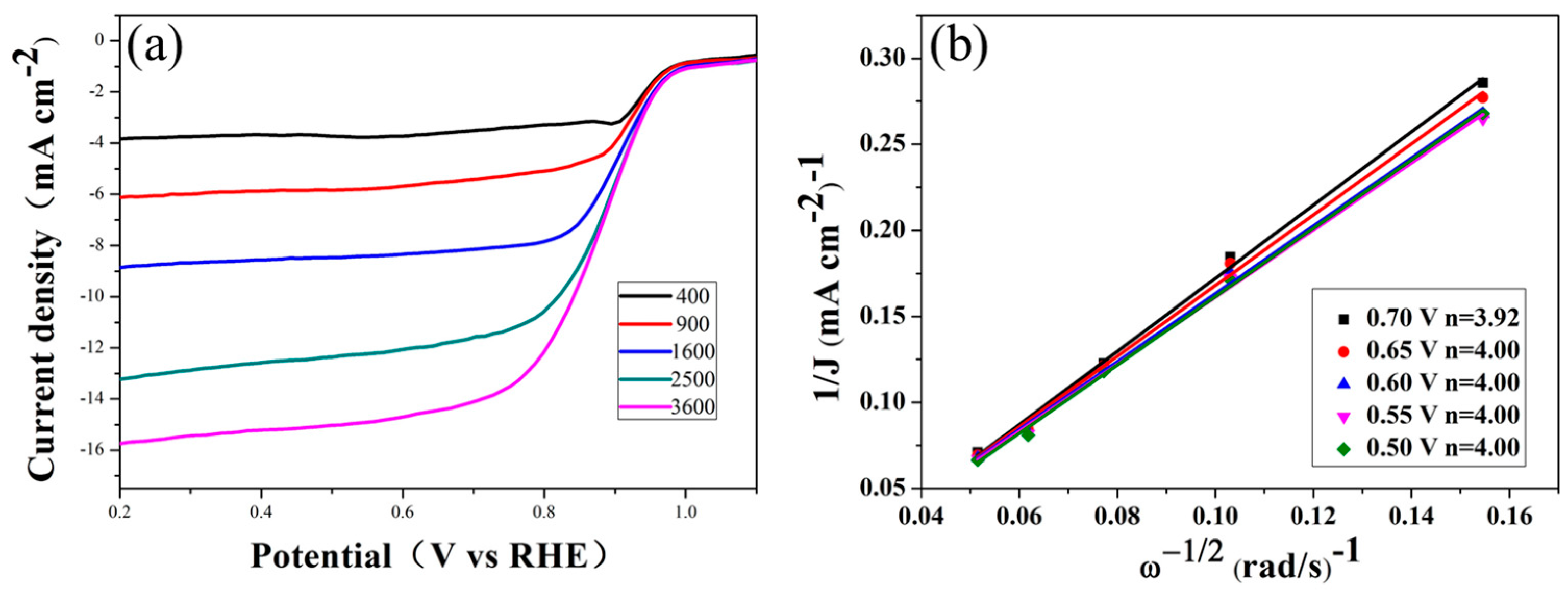
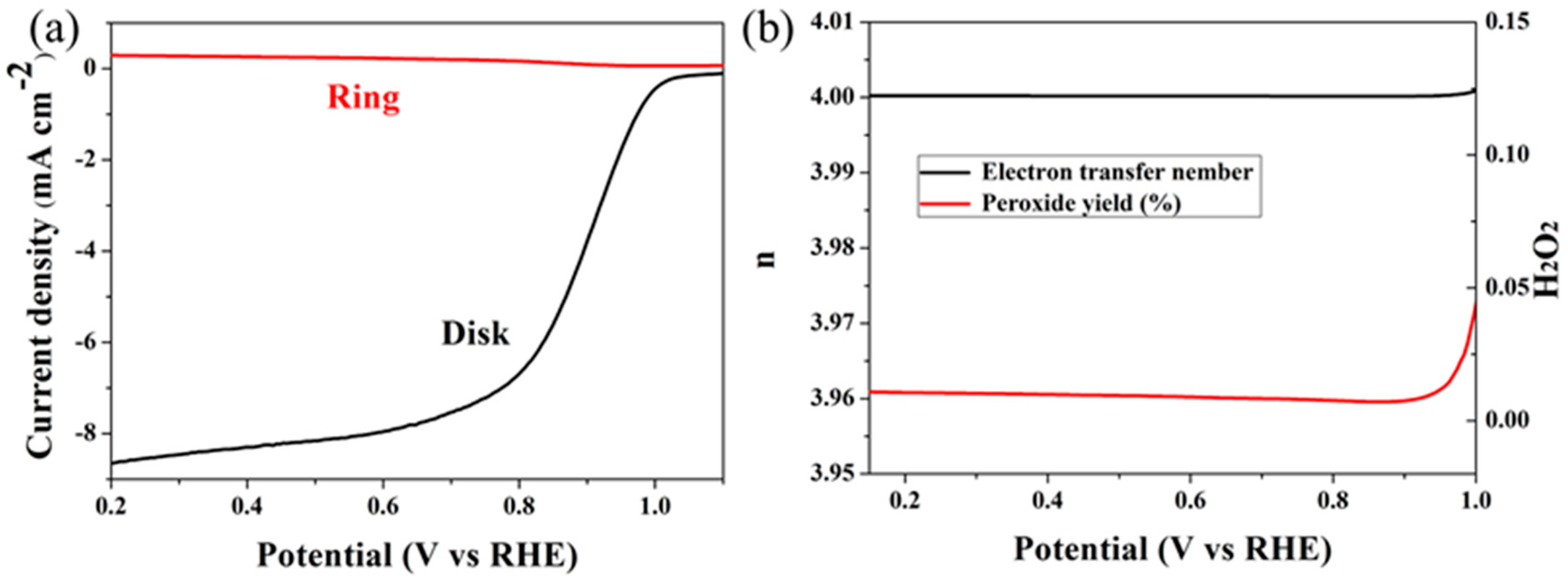
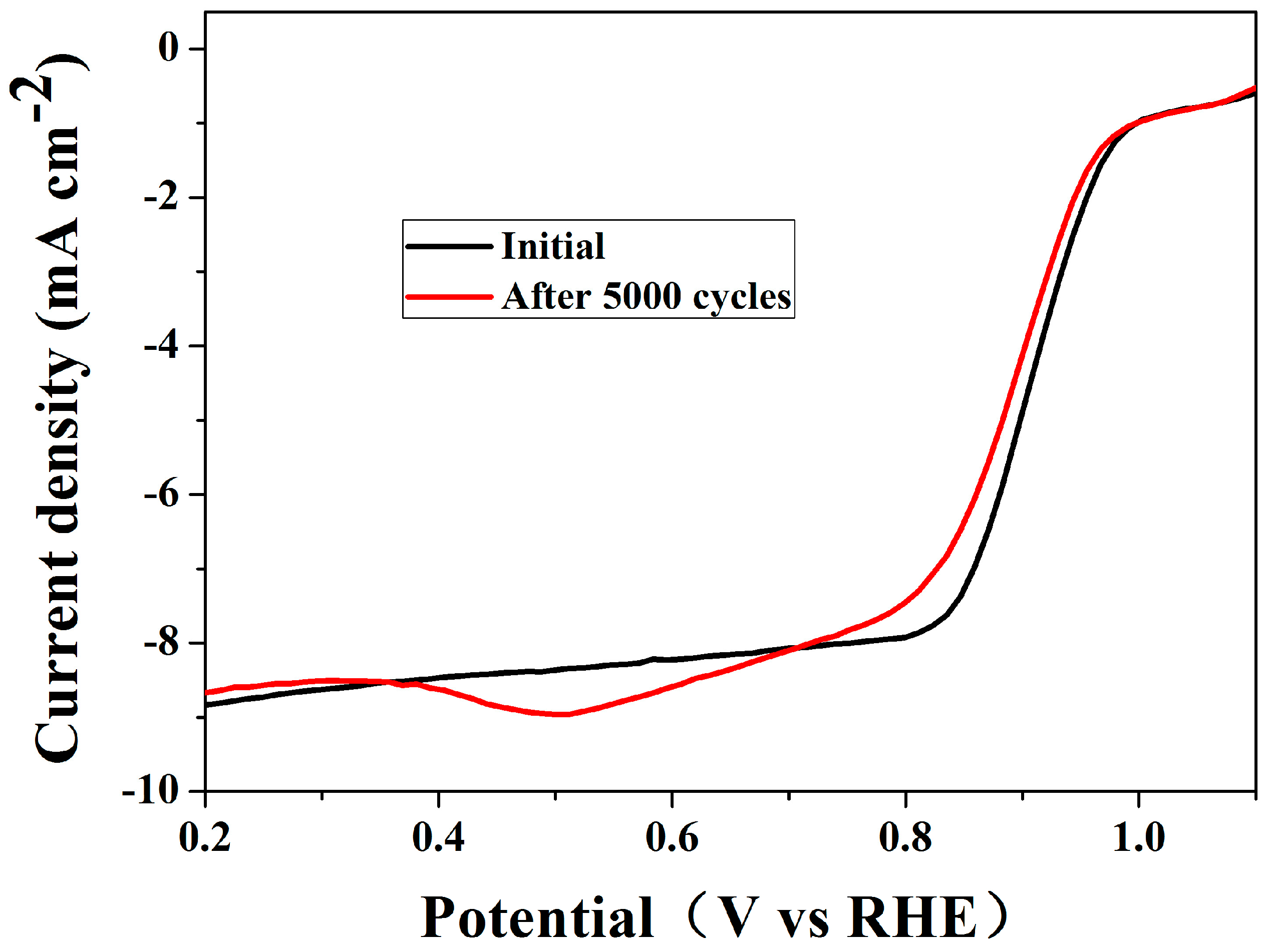
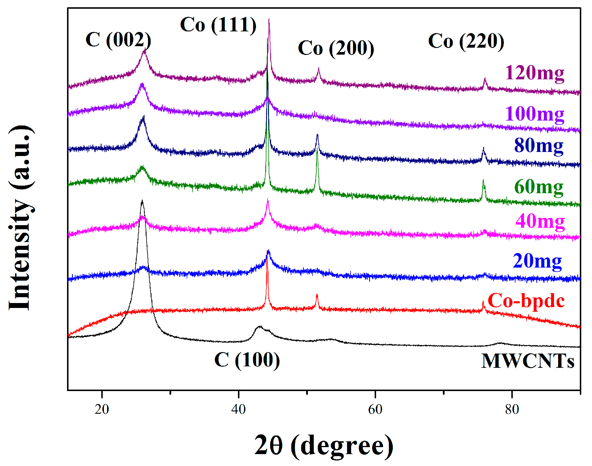
2. Results
3. Discussion
4. Materials and Methods
4.1. Catalyst Preparation
4.2. Materials Characterization
4.3. Electrochemical Test
5. Conclusions
Acknowledgments
Author Contributions
Conflicts of Interest
References
- Qiao, X.C.; Liao, S.J.; Zheng, R.P.; Deng, Y.J.; Song, H.Y.; Du, L. Cobalt and nitrogen co-doped graphene with inserted carbon nanospheres as an efficient bifunctional electrocatalyst for oxygen reduction and evolution. ACS Sustain. Chem. Eng. 2016, 4, 4131–4136. [Google Scholar] [CrossRef]
- Chu, S.; Majumdar, A. Opportunities and challenges for a sustainable energy future. Nature 2012, 488, 294–303. [Google Scholar] [CrossRef] [PubMed]
- Lai, Q.X.; Su, Q.; Gao, Q.W.; Liang, Y.Y.; Wang, Y.X.; Yang, Z.; Zhang, X.G.; He, J.P.; Tong, H. In situ self-scrificed template synthesis of Fe-N/G catalysts for enhanced oxygen reduction. ACS Appl. Mater. Interfaces 2015, 7, 18170–18178. [Google Scholar] [CrossRef] [PubMed]
- Xia, B.Y.; Yan, Y.; Wang, X.; Lou, X.W. Recent progress on graphene-based hybrid electrocatalysts. Mater. Horiz. 2014, 1, 379–399. [Google Scholar] [CrossRef]
- Chen, A.; Holt-Hindle, P. Platinum-based nanostructured materials: Synthesis, properties, and applications. Chem. Rev. 2010, 110, 3767–3804. [Google Scholar] [CrossRef] [PubMed]
- Zhang, Y.; Huang, L.B.; Jiang, W.J.; Zhang, X.; Chen, Y.Y.; Wei, Z.D.; Wan, L.J.; Hu, J.S. Sodium chloride-assisted green synthesis of a 3D Fe–N–C hybrid as a highly active electrocatalyst for the oxygen reduction reaction. J. Mater. Chem. A 2016, 4, 7781–7787. [Google Scholar] [CrossRef]
- Wang, Y.; Nie, Y.; Ding, W.; Chen, S.G.; Xiong, K.; Qi, X.Q.; Zhang, Y.; Wang, J.; Wei, Z.D. Unification of catalytic oxygen reduction and hydrogen evolution reactions: Highly dispersive Co nanoparticles encapsulated inside Co and nitrogen co-doped carbon. Chem. Commun. 2015, 51, 8942–8945. [Google Scholar] [CrossRef] [PubMed]
- Shang, L.; Yu, H.J.; Huang, X.; Bian, T.; Shi, R.; Zhao, Y.F.; Waterhouse, G.I.N.; Wu, L.Z.; Tung, C.H.; Zhang, T.R. Well-dispersed ZIF-derived Co,N-co-doped carbon nanoframes through mesoporous-silica-protected calcination as efficient oxygen reduction electrocatalysts. Adv. Mater. 2016, 28, 1668–1674. [Google Scholar] [CrossRef] [PubMed]
- Shao, M.H.; Chang, Q.W.; Dodelet, J.P.; Chenitz, R. Recent advances in electrocatalysts for oxygen reduction reaction. Chem. Rev. 2016, 116, 3594–3657. [Google Scholar] [CrossRef] [PubMed]
- Hu, K.; Tao, L.; Liu, D.D.; Huo, J.; Wang, S.Y. Sulfur-doped Fe/N/C nanosheets as highly efficient electrocatalysts for oxygen reduction reaction. ACS Appl. Mater. Interfaces 2016, 8, 19379–19385. [Google Scholar] [CrossRef] [PubMed]
- Yao, Y.; Xiao, H.; Wang, P.; Su, P.P.; Shao, Z.G.; Yang, Q.H. CNTs@Fe–N–C core–shell nanostructures as active electrocatalyst for oxygen reduction. J. Mater. Chem. A 2014, 2, 11768–11775. [Google Scholar] [CrossRef]
- Zhu, Y.S.; Zhang, B.S.; Liu, X.; Wang, D.W.; Su, D.S. Unravelling the structure of electrocatalytically active Fe-N complexes in carbon for the oxygen reduction reaction. Angew. Chem. Int. Ed. 2014, 53, 10673–10677. [Google Scholar] [CrossRef] [PubMed]
- Choi, C.H.; Baldizzone, C.; Polymeros, G.; Pizzutilo, E.; Kasian, O.; Schuppert, A.K.; Sahraie, N.R.; Sougrati, M.T.; Mayrhofer, K.J.J.; Jaouen, F. Minimizing operando demetallation of Fe-N-C electrocatalysts in acidic medium. ACS Catal. 2016, 6, 3136–3146. [Google Scholar] [CrossRef]
- Brouzgou, A.; Song, S.Q.; Liang, Z.X.; Tsiakaras, P. Non-precious electrocatalysts for oxygen reduction reaction in alkaline media: Latest achievements on novel carbon materials. Catalysts 2016, 6, 159. [Google Scholar] [CrossRef]
- Kadam, P.D.; Chuan, H.H. Erratum to: Rectocutaneous fistula with transmigration of the suture: A rare delayed complication of vault fixation with the sacrospinous ligament. Int. Urogynecol. J. 2016, 27, 505. [Google Scholar] [CrossRef] [PubMed]
- Proietti, E.; Jaouen, F.; Lefèvre, M.; Larouche, N.; Tian, J.; Herranz, J.; Dodelet, J.P. Iron-based cathode catalyst with enhanced power density in polymer electrolyte membrane fuel cells. Nat. Commun. 2011, 2, 416. [Google Scholar] [CrossRef] [PubMed]
- Nabae, Y.; Nagata, S.; Hayakawa, T.; Niwa, H.; Harada, Y.; Oshima, M.; Isoda, A.; Matsunaga, A.; Tanaka, K.; Aoki, T. Pt-free carbon-based fuel cell catalyst prepared from spherical polyimide for enhanced oxygen diffusion. Sci. Rep. 2016, 6, 23276. [Google Scholar] [CrossRef] [PubMed]
- Zhang, S.L.; Zhang, Y.; Jiang, W.J.; Liu, X.; Xu, S.L.; Huo, R.J.; Zhang, F.Z.; Hu, J.S. Co@N-CNTs derived from triple-role CoAl-layered double hydroxide as an efficient catalyst for oxygen reduction reaction. Carbon 2016, 107, 162–170. [Google Scholar] [CrossRef]
- Jahnke, H.; Schönborn, M.; Zimmermann, G. Organic dyestuffs as catalysts for fuel cells. Top. Curr. Chem. 1976, 61, 133–181. [Google Scholar] [PubMed]
- Ferrero, G.A.; Preuss, K.; Marinovic, A.; Jorge, A.B.; Mansor, N.; Brett, D.J.L.; Fuertes, A.B.; Sevilla, M.; Titirici, M.M. Fe-N-doped carbon capsules with outstanding electrochemical performance and stability for the oxygen reduction reaction in both acid and alkaline conditions. ACS Nano 2016, 10, 5922–5932. [Google Scholar] [CrossRef] [PubMed]
- Zhou, D.; Yang, L.P.; Yu, L.H.; Kong, J.H.; Yao, X.Y.; Liu, W.S.; Xua, Z.C.; Lu, X.H. Fe/N/C hollow nanospheres by Fe(iii)-dopamine complexation-assisted one-pot doping as nonprecious-metal electrocatalysts for oxygen reduction. Nanoscale 2015, 7, 1501–1509. [Google Scholar] [CrossRef] [PubMed]
- Yu, H.Y.; Fisher, A.; Cheng, D.J.; Cao, D.P. Cu,N-codoped hierarchical porous carbons as electrocatalysts for oxygen reduction reaction. ACS Appl. Mater. Interfaces 2016, 8, 21431–21439. [Google Scholar] [CrossRef] [PubMed]
- Fu, X.G.; Choi, J.Y.; Zamani, P.Y.; Jiang, G.P.; Hoque, M.A.; Hassan, F.M.; Chen, Z.W. Co-N decorated hierarchically porous graphene aerogel for efficient oxygen reduction reaction in acid. ACS Appl. Mater. Interfaces 2016, 8, 6488–6495. [Google Scholar] [CrossRef] [PubMed]
- Zhang, G.; Lu, W.T.; Cao, F.F.; Xiao, Z.D.; Zheng, X.S. N-doped graphene coupled with Co nanoparticles as an efficient electrocatalyst for oxygen reduction in alkaline media. J. Power Sources 2016, 302, 114–125. [Google Scholar] [CrossRef]
- Zhu, H.; Sun, Z.N.; Chen, M.L.; Cao, H.H.; Li, K.; Cai, Y.Z.; Wang, F.H. Highly porous composite based on tungsten carbide and N-doped carbon aerogels for electrocatalyzing oxygen reduction reaction in acidic and alkaline media. Electrochim. Acta 2017, 236, 154–160. [Google Scholar] [CrossRef]
- Zhou, X.J.; Bai, Z.Y.; Wu, M.J.; Qiao, J.L.; Chen, Z.W. 3-Dimensional porous N-doped graphene foam as a non-precious catalyst for the oxygen reduction reaction. J. Mater. Chem. A 2015, 3, 3343–3350. [Google Scholar] [CrossRef]
- Hao, J.H.; Yang, W.S.; Zhang, Z.; Tang, J.L. Metal-organic frameworks derived CoxFe1-xP nanocubes for electrochemical hydrogen evolution. Nanoscale 2015, 7, 11055–11062. [Google Scholar] [CrossRef] [PubMed]
- Huskić, I.; Pekov, I.V.; Krivovichev, S.V.; Friščić, T. Minerals with metal-organic framework structures. Sci. Adv. 2016, 2, e1600621. [Google Scholar] [CrossRef] [PubMed]
- You, S.J.; Gong, X.B.; Wang, W.; Qi, D.P.; Wang, X.H.; Chen, X.D.; Ren, N.Q. Enhanced cathodic oxygen reduction and power production of microbial fuel cell based on noble-metal-free electrocatalyst derived from metal-organic frameworks. Adv. Energy Mater. 2016, 6, 1501497. [Google Scholar] [CrossRef]
- Zhu, Q.L.; Xia, W.; Akita, T.; Zou, R.Q.; Xu, Q. Metal-organic framework-derived honeycomb-like open porous nanostructures as precious-metal-free catalysts for highly efficient oxygen electroreduction. Adv. Mater. 2016, 28, 6391–6398. [Google Scholar] [CrossRef] [PubMed]
- Zhang, Y.F.; Bo, X.J.; Nsabimana, A.; Han, C.; Li, M.; Guo, L.P. Electrocatalytically active cobalt-based metal–organic framework with incorporated macroporous carbon composite for electrochemical applications. J. Mater. Chem. A 2015, 3, 732–738. [Google Scholar] [CrossRef]
- Zhao, H.X.; Zou, Q.; Sun, S.K.; Yu, C.S.; Zhang, X.J.; Lia, R.J.; Fu, Y.Y. The ranostic metal–organic framework core–shell composites for magnetic resonance imaging and drug delivery. Chem. Sci. 2016, 7, 5294–5301. [Google Scholar] [CrossRef]
- Song, Y.H.; Li, X.; Sun, L.L.; Wang, L. Metal/metal oxide nanostructures derived from metal–organic frameworks. RSC Adv. 2015, 5, 7267–7279. [Google Scholar] [CrossRef]
- Mahmood, A.; Guo, W.H.; Tabassum, H.; Zou, R.Q. Metal-organic framework-based nanomaterials for electrocatalysis. Adv. Energy Mater. 2016, 6, 1600423. [Google Scholar] [CrossRef]
- Li, X.Z.; Fang, Y.Y.; Lin, X.Q.; Tian, M.; An, X.C.; Fu, Y.; Li, R.; Jin, J.; Ma, J. MOF derived Co3O4nanoparticles embedded in N-doped mesoporous carbon layer/MWCNT hybrids: Extraordinary bi-functional electrocatalysts for OER and ORR. J. Mater. Chem. A 2015, 3, 17392–17402. [Google Scholar] [CrossRef]
- Maghsodi, A.; Milani, H.M.; Dehghani, M.M.; Kheirmand, M.; Samiee, L.; Shoghi, F.; Kameli, M. Exploration of bimetallic Pt-Pd/C nanoparticles as an electrocatalyst for oxygen reduction reaction. Appl. Surf. Sci. 2011, 257, 6353–6357. [Google Scholar] [CrossRef]
- Yi, L.H.; Liu, L.; Liu, X.; Wang, X.Y.; Yi, W.; He, P.Y.; Wang, X.Y. Carbon-supported Pt-Co nanoparticles as anode catalyst for direct borohydride-hydrogen peroxide fuel cell: Electrocatalysis and fuel cell performance. Int. J. Hydrog. Energy 2012, 37, 12650–12658. [Google Scholar] [CrossRef]
- Geng, D.S.; Chen, Y.; Chen, Y.G.; Li, Y.L.; Li, R.Y.; Sun, X.L.; Ye, S.Y.; Knights, S. High oxygen-reduction activity and durability of nitrogen-doped graphene. Energy Environ. Sci. 2011, 4, 760–764. [Google Scholar] [CrossRef]
- Xia, W.; Zou, R.Q.; An, L.; Xia, D.G.; Guo, S.J. A metal–organic framework route to in situ encapsulation of Co@Co3O4@C core@bishell nanoparticles into a highly ordered porous carbon matrix for oxygen reduction. Energy Environ. Sci. 2015, 8, 568–576. [Google Scholar] [CrossRef]
- Jiang, H.L.; Yao, Y.F.; Zhu, Y.H.; Liu, Y.Y.; Su, Y.H.; Yang, X.L.; Li, C.Z. Iron carbide nanoparticles encapsulated in mesoporous Fe-N-doped graphene-like carbon hybrids as efficient bifunctional oxygen electrocatalysts. ACS Appl. Mater. Interfaces 2015, 7, 21511–21520. [Google Scholar] [CrossRef] [PubMed]
- Zhao, P.P.; Xu, W.; Hua, X.; Luo, W.; Chen, S.L.; Cheng, G.Z. Facile synthesis of a N-doped Fe3C@CNT/porous carbon hybrid for an advanced oxygen reduction and water oxidation electrocatalyst. J. Phys. Chem. C 2016, 120, 11006–11013. [Google Scholar] [CrossRef]
- Vezzù, K.; Delpeuch, A.B.; Negro, E.; Polizzi, S.; Nawn, G.; Bertasi, F.; Pagot, G.; Artyushkova, K.; Atanassov, P.; Noto, V.D. Fe-carbon nitride “core-shell” electrocatalysts for the oxygen reduction reaction. Electrochim. Acta 2016, 222, 1778–1791. [Google Scholar] [CrossRef]
- Negro, E.; Polizzi, S.; Vezzu, K.; Toniolo, L.; Cavinato, G.; Noto, V.D. Interplay between morphology and elecrtrochemical performance of “core-shell” electrocatalysts for oxygen reduction reaction based on a PtNix carbon nitride “shell” and a pyrolyzed polyketone nanoball “core”. Int. J. Hydrog. Energy 2014, 39, 2828–2841. [Google Scholar] [CrossRef]


| Elements | 0 | 20 | 40 | 60 | 80 | 100 | 120 |
|---|---|---|---|---|---|---|---|
| C | 66.65 | 88.01 | 89.75 | 91.05 | 92.51 | 91.94 | 92.67 |
| O | 23.79 | 7.24 | 6.06 | 5.65 | 4.39 | 4.9 | 4.79 |
| Co | 6.01 | 3.12 | 2.35 | 1.44 | 1.24 | 1.14 | 1.3 |
| N | 3.54 | 1.63 | 1.84 | 1.86 | 1.87 | 2.02 | 1.24 |
© 2017 by the authors. Licensee MDPI, Basel, Switzerland. This article is an open access article distributed under the terms and conditions of the Creative Commons Attribution (CC BY) license (http://creativecommons.org/licenses/by/4.0/).
Share and Cite
Zhu, H.; Li, K.; Chen, M.; Cao, H.; Wang, F. A Novel Metal–Organic Framework Route to Embed Co Nanoparticles into Multi-Walled Carbon Nanotubes for Effective Oxygen Reduction in Alkaline Media. Catalysts 2017, 7, 364. https://doi.org/10.3390/catal7120364
Zhu H, Li K, Chen M, Cao H, Wang F. A Novel Metal–Organic Framework Route to Embed Co Nanoparticles into Multi-Walled Carbon Nanotubes for Effective Oxygen Reduction in Alkaline Media. Catalysts. 2017; 7(12):364. https://doi.org/10.3390/catal7120364
Chicago/Turabian StyleZhu, Hong, Ke Li, Minglin Chen, Hehuan Cao, and Fanghui Wang. 2017. "A Novel Metal–Organic Framework Route to Embed Co Nanoparticles into Multi-Walled Carbon Nanotubes for Effective Oxygen Reduction in Alkaline Media" Catalysts 7, no. 12: 364. https://doi.org/10.3390/catal7120364