Photocatalytic Membrane Reactors (PMRs) in Water Treatment: Configurations and Influencing Factors


1
School of Environment & Natural Resources, Renmin University of China, Beijing 100872, China
2
Key Laboratory of Urban Stormwater System and Water Environment, Ministry of Education, Beijing University of Civil Engineering and Architecture, Beijing 100044, China
*
Authors to whom correspondence should be addressed.
Catalysts 2017, 7(8), 224; https://doi.org/10.3390/catal7080224
Submission received: 7 June 2017
/
Revised: 14 July 2017
/
Accepted: 17 July 2017
/
Published: 25 July 2017
(This article belongs to the Special Issue Catalysis in Membrane Reactors)
Abstract
:The lack of access to clean water remains a severe issue all over the world. Coupling photocatalysis with the membrane separation process, which is known as a photocatalytic membrane reactor (PMR), is promising for water treatment. PMR has developed rapidly during the last few years, and this paper presents an overview of the progress in the configuration and operational parameters of PMRs. Two main configurations of PMRs (PMRs with immobilized photocatalyst; PMRs with suspended photocatalyst) are comprehensively described and characterized. Various influencing factors on the performance of PMRs, including photocatalyst, light source, water quality, aeration and membrane, are detailed. Moreover, a discussion on the current problems and development prospects of PMRs for practical application are presented.
1. Introduction
With the fast expansion of industrialization and population growth, in addition to increasing water pollution, shortage of clean water sources has turned into a severe problem all over the world. Over 15% of the world’s population lack access to reliable water sources, which are essential for public health [1]. Waterborne diseases are common and often highly epidemic in both industrialized and developing countries [2]. Therefore, it is extremely desirable to develop stable, high-efficiency and low-cost water treatment technologies.
Heterogeneous photocatalysis is one of the most promising water treatment technologies, and it has been proved to exhibit high efficiency in the degradation of organic contaminants and disinfection of pathogenic microorganisms [3,4]. In a photocatalytic system, electrons transfer to the conduction band and form electron-hole pairs after the semiconductor photocatalysts are excited by high-energy photons, and the electrons and holes further react with the oxygen and hydroxyl groups in water, generating various reactive oxygen species (ROSs) including •OH, •O2−, H2O2, 1O2. These generated ROSs have strong oxidizing properties, and can degrade different types of refractory organic pollutants as well as inactivate various pathogenic microorganisms [3,4,5,6]. Among all the photocatalysts, TiO2 is studied most widely because of its low toxicity, low cost, high activity and high chemical stability [7]. However, TiO2 only works under UV irradiation that accounts for about 4% of the solar spectrum that reaches earth’s ground level [8]. To deal with this defect, many researchers modify TiO2 through non-metal/metal doping, coupling semiconductors or dye sensitization to improve its utilization of solar energy [9,10,11,12]. Besides, some novel non-TiO2-based photocatalysts possessing narrow band-gaps such as Ag-AgI and C3N4 can also achieve the response of visible light [13,14,15,16]. This significantly reduces the energy consumption of photocatalysis and makes it more possible for industrialization at large scale. In addition, heterogeneous photocatalysis also has other advantages compared with traditional water treatment technologies, such as (1) a broad spectrum of effectiveness against various contaminants; (2) ambient operating pressure and temperature; (3) complete degradation of the parent pollutants and their intermediate products [3]. In spite of the above advantages, the practical application of photocatalysis for water treatment is still facing technical challenges. Photocatalysts are mostly used as suspended powders in the photocatalytic reactors, since the utilization of slurries usually presents higher efficiency with respect to the use of immobilized films. However, it is difficult to separate the photocatalysts in slurries from the treated water for reuse. This has been identified as the major obstacle among the current engineering limitations of photocatalytic processes [3,17]. Thus, a separation/recovery step is required to realize the reuse of photocatalysts.
Membrane technology was first applied to water treatment processes in 1960s. Since then, it has been widely employed for the physical separation process of pollutants in water treatment plants [18]. The most frequently used membrane technologies in the water treatment field are microfiltration (MF), ultrafiltration (UF), nanofiltration (NF) and reverse osmosis (RO), in descending order of membrane pore sizes [19]. It has been widely proved in practice that the membrane separation process can remove the majority of the suspended solids, colloids and microorganisms effectively. In addition, it requires smaller floor space and sustains a more stable effluent quality than traditional water treatment technologies, attracting an increasing number of industrial applications. To date, it is estimated that approximately 60 million m3 of water is purified by membrane process every day [20]. Generally, membrane technology is an effective and mature method for a wide range of separation applications. Thus, it is reasonable to consider coupling the membrane process with heterogeneous photocatalysis in order to realize the reuse of photocatalysts in the photocatalytic system, which are known as photocatalytic membrane reactors (PMRs).
PMRs have several distinct features in comparison with conventional photocatalytic reactors, such as: (1) keeping the photocatalyst confined in the reaction environment through membrane technology; (2) realizing a continuous process with simultaneous separation of photocatalysts and products from the reaction environment; (3) separating the photocatalysts from the treated water [21,22]. The first two advantages are conducive to improving process controllability, stability and efficiency. The third advantage is beneficial to re-collecting the photocatalysts for reusing in further runs. Moreover, it is also beneficial to save energy as well as cut down the size of installation, because additional operations like coagulation—flocculation—sedimentation are indispensable for traditional photocatalytic reactors in which photocatalysts have to be removed from the treated solution to ensure the effluent quality [23]. The growing interest in PMRs for water treatment can be manifested by the recent number of publications in Web of ScienceTM. Figure 1 presents the number of publications on the topic of “PMRs” and “PMRs for water treatment” from 1996 to 2016. Early in the 1990s, some researchers started to employ ceramic and cellulose membranes to immobilize TiO2, which was the embryonic form of PMRs [24,25,26]. Since then, the number of publications on the topic of “PMRs” increased significantly, indicating the good development of PMR research progress. During 2016, 132 publications were published on the topic of “PMRs”, which was far more than in the early decades. It is obvious that most of the PMRs are designed for water treatment, since the publications on the topic of “PMRs for water treatment” accounts for over 70% of the publications on the topic of “PMRs”, and the rest of the publications mainly aim at hydrogen production [27]. On the basis of the deployed state of the photocatalysts, PMR configurations for water treatment could mainly be divided into two categories: (1) PMRs with photocatalyst suspended in feed solution; (2) PMRs with photocatalyst immobilized in/on the membrane. Owing to larger active surface area of the photocatalyst in suspended system compared to that of immobilized system, the PMRs with suspended photocatalyst have been proved to achieve higher efficiency, attracting more attention of researchers [28,29,30]. In addition to reactor configurations, various influencing factors, such as photocatalyst, light source and membrane, also affect the water treatment performance of PMRs. These influencing factors will bring about changes in heterogeneous photocatalysis process and/or in membrane process, ultimately making a difference in PMRs performance.
Taking into consideration that PMRs have developed rapidly in the last few years, many novel configurations and new applications have been described in the literature. After Mozia’s [23] overview of the configurations and applications of PMRs for water treatment in 2010, some new reviews on related topics have been presented with different emphases. Mozia et al. [31] focused on the fundamentals, membrane materials and operational issues of PMRs. They systematically introduced the photocatalytic properties of photocatalysts and the types of membranes applied in PMR systems. Some aspects of membrane operations, such as fouling and separation of photocatalysts were also discussed. Zhang et al. [32] focused on the membrane fouling in PMRs for water treatment and discussed the relationship between photocatalysis and membrane fouling in detail. Molinari et al. [33] paid attention to the application of PMRs in degradation of organic pollutants and in synthesis of organic compounds. These reviews concentrated on different aspects of PMR systems, however, the PMR configuration, which is also an important aspect, was rarely discussed at considerable length. Molinari et al. [34] gave a systematic introduction of PMR configurations for water treatment and chemical production in 2013. They presented different types of PMR configurations and discussed their advantages and disadvantages in detail. However, they only introduced the most typical reactor designs for each type of PMR, and some novel designs developed in recent years were hardly presented. Therefore, it is of significance to review the research progress of PMR configuration involving both typical and new designs. In addition to configurations, the influencing factors that affect the PMR performance are also vital to the practical application of PMRs. However, this aspect was rarely reviewed in a systematic way. In the published reviews containing this content, the authors mostly focused on the influencing factors of the photocatalytic process instead of the PMR performance [23,32]. In fact, some influencing factors of the photocatalysis would also affect the membrane process, and some additional factors should be taken into consideration when the membrane module is coupled with the photocatalytic reactor. Therefore, it is meaningful to systematically review the influencing factors of PMR performance.
In this paper, typical and new types of configurations are both presented in detail, giving a comprehensive introduction of the research progress in terms of PMR configurations. In addition, the influencing factors of PMR performance are also discussed in depth, which is not or rarely conducted in other reviews. Generally, this paper presents an overview of the progresses in the configurations and influencing factors of PMRs. Two main configurations of PMRs (PMRs with immobilized photocatalyst; PMRs with suspended photocatalyst) are introduced comprehensively. Various influencing factors on the performance of PMR including photocatalyst, light source, water quality, aeration and membrane are also detailed.
2. Configurations of PMRs
As mentioned above, the configurations of PMRs can be divided into PMRs with immobilized photocatalyst and PMRs with suspended photocatalyst. For the former type of PMRs, they can be further classified into three groups on the base of the combination form between membrane and photocatalyst: (1) photocatalyst coated on the membrane; (2) photocatalyst blended with the membrane; and (3) free-standing photocatalytic membrane. In PMRs with photocatalyst coated/blended with the membrane, the photocatalysts are usually fabricated and then coated/blended with a commercial membrane via an immobilization step, while in PMRs with free-standing photocatalytic membrane, the membrane itself is manufactured with a pure photocatalyst. For the latter type of PMRs, Mozia [23] divided them into three types according to the position of the light source: (a) above the feed tank; (b) above the membrane unit; and (c) above an additional vessel, which is placed between the membrane unit and the feed tank. However, this classification could not directly reflect the photocatalysis-membrane process, which is the core of PMRs configurations. Here, in this paper, PMRs with suspended photocatalyst were classified into two major types: (1) integrative type; and (2) split type, based on the combination form between heterogeneous photocatalysis module and membrane module. In integrative-type PMRs, the photocatalytic reaction and membrane separation processes are merged in one apparatus. While in split-type PMRs, the two processes take place in separate apparatuses. All the configurations mentioned above will be described in detailed in the following parts. In addition, some novel PMR configurations developed in recent year will also be introduced.
2.1. PMRs with Immobilized Photocatalyst
In some cases of PMRs with immobilized photocatalyst, the photocatalyst is immobilized on an inert support such as glass substrates, in which the membrane module is appended for the separation of the photocatalytic oxidation products. While in most cases, the photocatalyst is fixed on/in a certain support membrane, which is conducive to the separation of photocatalyst from the effluent, avoiding secondary pollution and photocatalyst losses. The support membrane can act as not only the support for photocatalyst but also the selective barrier for the contaminants to be removed. For PMRs with photocatalyst coated on the membrane, the photocatalyst is coated tightly on the surface of the support membrane. Polymeric and ceramic membranes are commonly applied as the supports. Meanwhile, various organic and inorganic materials have also been used in some researches. Iglesias et al. [17] summarized different ways of manufacturing membranes with a catalyst layer on the surface, including dip-coating, electrospraying TiO2 particles, magnetron sputtering or deposition of gas phase photocatalyst nanoparticles. Table 1 presents several examples of membranes coated with photocatalyst by different methods. For PMRs with photocatalyst blended with the membrane, the photocatalyst is blended into the membrane matrix, reducing the possibility of photocatalyst leaching compared to photocatalytic-coated membranes [35]. Most researchers selected polyvinylidene fluoride (PVDF) polymeric membranes for the photocatalyst entrapment [36,37,38,39,40,41,42,43], while polyethersulfone (PES) [44,45,46], polyacrylonitrile (PAN) [47], cellulose acetate (CA) [48,49], polystyrene (PS) [50] and polysulfone (PSF) [51,52] were also used. For PMRs with free-standing photocatalytic membrane, its production is often performed via the electrochemical anodization of a titanium metallic substrate, followed by the separation of the TiO2 nanotube film and different annealing treatments [17]. Compared to membrane with coated or blended photocatalyst, the immobilization step is unnecessary for freestanding photocatalytic membrane, thus reducing the possibility of photocatalyst leaching. All the three types of photocatalytic membranes with immobilized photocatalyst have been applied in PMR systems.
In PMRs with immobilized photocatalysts, the membrane separation process and heterogeneous photocatalysis take place in the same vessel. Thereby most of the immobilized PMR systems consist of a feed tank and only one reaction tank. The light sources are usually placed above the membrane module for UV/visible light irradiation. The PMR system could be operated in either dead-end mode or cross flow mode. Some typical configurations with different features are described as follows.
Figure 2 presents a TiO2-halloysite nanotubes/PVDF-based photocatalytic membrane reactor for hydrocarbon degradation and separation of bilge water. The batch installation was operated in dead end mode. The membrane was immersed in the PMR under water level. The water sample was transferred to the PMR from the feed tank for further operation. In the first 6 h, the peristaltic pump was switched off, and the water sample in the PMR was treated by the photocatalytic membrane under UVC light irradiation. Then, the peristaltic pump was switched on for 2 h and the permeate flow was collected in the permeation tank. The results showed that 99.9% of hydrocarbons were removed by the PMR system after the 8 h process, and only 1.0 ppb TiO2 leaching was detected in the permeate tank, indicating that TiO2 was immobilized tightly with the membrane. In this type of batch system, the water sample was kept in the reactor without recycling, thus the molecules to be degraded could not contact with the photocatalyst and light source adequately, resulting in relatively lower photocatalytic efficiency.
Figure 3 shows a laboratory-scale PMR system with two flow configurations that could be operated in recirculating batch operation mode for the degradation of carbamazepine (CBZ). N-doped TiO2 photocatalytic film was coated on the surface of commercial α-Al2O3 membranes. A solar-simulator was placed on top as the light source. A quartz glass was positioned above the photocatalytic membrane to keep a stable water level as well as to seal the reaction chamber. Before the light was turned on, the prepared feed solution was recirculated through the system for 30 min, ensuring that the CBZ achieved an adsorption/desorption equilibrium on the photocatalytic membrane. When the system was operated in FC 1 mode, the feed solution was pumped from the uncoated side to the coated side of the photocatalytic membrane. In addition, in FC 2 mode, the feed solution flowed on the surface of the coated side of the membrane without filtration. The valve was closed to keep the operation in a dead-end mode. The permeate flow was recycled back to the feed tank during the operation. The results showed that the membrane permeability after coating procedures was found to decrease by 50% and 12% for 200 nm and 800 nm Al2O3 membranes, respectively. A significantly higher CBZ reaction rate was achieved in FC 1 than FC 2 configuration, which might be due to the increased contact between the reactants and the catalytically active sites. In this system, the modification of TiO2 with nitrogen realized the visible light response, making it possible to utilize solar energy as the light source, thereby increased the feasibility of PMR for large-scale applications in the future.
The two PMRs systems described above both operated in dead end mode. In this mode, the feed stream was pumped through the membrane to be a filtrate. Therefore, the separated substrates would accumulate on the membrane surface eventually and formed into a cake layer that resulted in the reduction of photocatalytic performance. Thus, the dead end mode is not feasible for most of the large-scale industrial applications. For this problem, cross flow mode would be a better option, where the feed stream is pumped to the coated side of the photocatalytic membrane and flows in parallel with the surface of the membrane. The permeate flow moves through the membrane in a direction perpendicular to the membrane surface while the retentate flow can be discharged or pumped back into the feed tank [37,58]. The membrane fouling is reduced in cross flow mode since the tangential feeding flow tends to remove the deposited substances on the surface of the membrane.
Figure 4 present a lab scale PMR in cross flow mode with LiCl-TiO2-PVDF membrane for the removal of natural organic matters (NOM). A cooling system was connected to the feed tank to keep the temperature of the solution at 25 °C. A quartz glass was placed above the photocatalytic membrane. The feed solution was pumped to the membrane cell. After the membrane process, the permeate along with the retentate were both returned back into the feed tank. The results showed that the LiCl-TiO2-PVDF membrane was able to achieve high NOM removal efficiency as well as decreased membrane fouling in cross flow mode.
As presented in Figure 5, A PMR system with Ag-TiO2/Hydroxyapatite/Al2O3 composite membrane was operated in cross flow mode for humic acid (HA) removal. The reactor was made of polymethyl methacrylate and possessed a total effective surface area of 11.34 cm2 (π × 1.9 cm × 1.9 cm). A quartz cooling thimble was placed around the UV lamp to avoid the effect of heat transfer without light shielding. The temperature of the test solution was kept at a constant value by a temperature control unit. Cross flow velocity and feed pressure were controlled by a backpressure regulator and a bypass valve respectively. In this system, the feed solution was pumped to the reactor, then the permeate was collected to the analytical balance for further test, while the retentate was cycled back to feed tank. The results showed that the HA removal and permeate flux of the membrane were both improved under UV irradiation.
In most of the PMRs described in the literature, the membrane bears just one photocatalytic active side. Romanos et al. designed a continuous cross-flow PMR configuration with double-side TiO2-modified NF membranes for methyl orange degradation. The schematic diagram is shown in Figure 6a [61]. In this system, the feed stream was controlled by a fluid delivery system. The photocatalytic cell unit consisted of an outer Plexiglas tube and an inner tube made of NF membrane with TiO2-modified active layers on both sides. The two as mentioned tubes defined the reactor into an outer flow channel and an inner flow channel. Four 9 W UV lamps were used as the light source for external surface of the membrane, while 15 UVA miniature LEDs were used as the light source for inner membrane surface. The ends of the inner tube (membrane) were open in air. During the experiment, the feed stream was transferred to the outer flow channel and flowed in the upward direction. The retentate was discharged from the water outlet on the top, and the permeate was discharged from the outlet at the bottom. Romanos’s group further improved the device in their following studies [62,63,64]. As shown in Figure 6b, an intermediate Plexiglas tube was added between the outer tube and the membrane. Thereby a third flow channel between the outer tube and the intermediate tube was appended. In this appended channel, reactive photocatalyst immobilized in/on carriers with high grade of transparency like polymer fibers could be attached. Thus, the feed solution underwent an additional photocatalytic process, achieving better photocatalytic performance than the unimproved system.
2.2. PMRs with Suspended Photocatalyst
In PMRs with suspended photocatalyst, the photocatalyst is dispersed in the feed solution evenly, and a membrane module is applied independently for the recovery of photocatalyst from the reaction solution. One distinct advantage of such a system is that the photocatalyst can contact with the pollutants sufficiently due to higher surface area, while the immobilized system is usually hindered by the mass transfer limitation over the immobilized layer of photocatalysts [3]. In addition, the increase of photocatalyst dosage in a wide range is feasible in suspended system, while it is not available for immobilized system because of the limited surface area of the membrane. Generally, PMR with suspended photocatalyst exhibits higher photocatalytic efficiency and is more promising for large-scale industrial applications. According to the combination form between photocatalysis and membrane process, the suspended PMRs configuration is classified into integrative type and split type. Both of them are described in the following sections.
2.2.1. Split-Type PMRs with Suspended Photocatalyst
The photocatalytic reactor and membrane module are split completely in split-type PMRs with suspended photocatalyst. Its configuration is quite clearly structured, which is convenient for installation and maintenance. In addition, the UV irradiation or reactive oxygen species won’t damage the membrane, which could happen in immobilized PMRs due to the direct contact between light and membrane surface. However, the photocatalyst has to be transferred to the membrane module for separation, making it easy for photocatalyst to deposit in the corner of the pipeline, ultimately affecting photocatalytic performance.
Figure 7 presents a typical split-type PMR with suspended photocatalyst [65]. A UV lamp with the peak wavelength of 253.7 nm was placed inside the reactor. Before starting the photocatalytic reaction, the lamp was turned off and the mixture of ZnO and Congo red (CR) dye was stirred sufficiently in order to achieve adsorption—desorption equilibrium. A water chiller was applied to keeping the operation temperature at 25 °C. The feed solution was transferred to the photoreactor for a 4 h photocatalysis process, and then pumped to the membrane unit for photocatalyst separation. The retentate was cycled back to the feed tank while the permeate was collected for analysis. The results showed that the CR removal in photocatalytic process was 72%, and increased to 100% after the NF membrane process. EDX analysis confirmed that the photocatalyst did not pass through the membrane pores to the final stream. This indicated that the NF membrane was able to efficiently reject photocatalysts as well as target pollutants. Similar configurations have also been applied in other studies [66,67].
In the lab-scale split PMR presented in Figure 8, the UV lamps were placed both in the photocatalytic feed tank and on top of the membrane unit. The hybrid set up is composed of an inline slurry photocatalytic reactor and a cross flow microfiltration membrane module. Flat sheet microfiltration membrane was positioned between the transparent quartz cases. A UVA lamp was positioned above the membrane while three same lamps were positioned in the feed tank. A motorized stirrer was positioned in the feed tank to keep the photocatalyst distributed uniformly in the solution. The system was operated in two modes: (1) the lamps in photocatalytic reactor were turned on while that in membrane module was turned off; (2) the lamp above the membrane was turned on while those in photocatalytic reactor were turned off. For the former mode, the system was operated similarly to the PMR described in Figure 7. For the latter mode, the feed solution was first pre-treated by the photocatalyst and then the supernatant was collected for further photocatalysis—MF hybrid treatment with UVA illumination on the surface of the membrane. This mode was designed for investigating whether the photocatalytic process on the membrane could control membrane fouling effectively. The results showed that the irradiation of UVA on membrane surface in presence of TiO2 yielded in an increase in permeate flux. However, it was also proposed that the membrane structural damage due to UVA irradiation was non-negligible.
The majority of the PMRs developed by the researchers were in laboratory scale; only few researchers designed PMRs in pilot scale. Karabelas’s group developed a laboratory pilot PMR system firstly [69], and then enlarged it into pilot scale in the following study [70]. The pilot-scale PMR mainly consisted of a membrane vessel and a UV treatment system as presented in Figure 9. The working volume of them was 10 L and 15 L respectively. The UF hollow fibers membrane with the total surface area of 4.19 m2 was submerged in the membrane vessel. Four 39 W germicidal lamps were encased within the quartz sleeves, and submerged in the UV chamber. A number of unit automations such as level control unit, backwashing unit and in situ cleaning unit were also applied in the PMR system. The total treatment capacity of the system was 1.2 m3/d. The pilot-scale PMR could be operated in an automatic mode, which meant that it was able to run stably for a long time in an unattended condition. In addition, the system could be monitored in a remote distance thanks to the wireless communication system. Furthermore, the energy consumption appeared to be comparable with traditional water treatment technologies, indicating that the novel PMR system was a promising water purification technology. Besides, Benotti et al. [71] developed a pilot PMR system to remove thirty-two pharmaceuticals, endocrine disrupting and estrogenic compounds from water. Augugliaro et al. [72] designed a pilot-scale PMR to degrade lincomycin in aqueous medium under sunlight. Overall, the studies on pilot-scale PMR system are relatively insufficient, and more efforts need to be dedicated to this significant research field.
2.2.2. Integrative-Type PMRs with Suspended Photocatalyst
In integrative-type PMRs with suspended photocatalyst, hollow fiber membranes are mostly used to construct the membrane module. The membrane is usually submerged in the photocatalytic tank with suspended photocatalyst. The solution is drawn from the outer to the inner side of the membrane under a slight negative pressure, while photocatalyst is intercepted on the outer membrane surface, ensuring that the photocatalyst content is constant in the photocatalytic tank. In this configuration, only two streams (feed and permeate) exist during the membrane process, which is similar to the dead-end configuration exhibited in Figure 2 and Figure 3. However, the membrane fouling can be reduced by specific constructions (such as agitation and aeration) of the module in integrative system, making it more applicable than dead-end system. In addition, the integration of photocatalysis and membrane module reduces the pipe length, the head losses and occupation area, thus the investment and operation cost is cut down.
As shown in Figure 10, a typical lab-scale integrative PMR was applied for fulvic acid removal [73]. The Plexiglas reactor possessed an effective working volume of 3.2 L. In order to avoid the damages to the membrane module caused by UV irradiation, a light baffle was applied to separating the reactor into two regions: the photocatalytic region and the membrane region. The UV lamp was suspended vertically at the center of the photocatalytic region. Recirculation cooling water was used to maintain the reaction temperature at 20 °C. A porous titanium plate was placed under the membrane module in order to supply air into the system, which was conducive to provide dissolved oxygen (DO) for photocatalytic reaction, fluidize the TiO2 particles and create abundant turbulence along the surface of the membrane. A suction pump was employed to obtain permeate from the membrane module. The water level in the reactor was controlled by a water level sensor. The membrane was cleaned after each experiment by gas backflushing followed by tap water back-flushing. To improve the UV utilization efficiency, a reflecting aluminum foil was applied to covering the exterior wall of the reactor. The results showed that the photocatalyst could be separated by the MF membrane easily. In addition, the permeate flux rate of MF membrane was improved when the commercial P25 was replaced by nano-structured TiO2, thus reducing the membrane fouling phenomenon. Similar integrative PMR configurations were also applied in other studies for the removal of virus [74], para-chlorobenzoate [75] and secondary effluent organics [76].
Figure 11 presents a different configuration of integrative PMR. The system was used to remove pharmaceuticals and endocrine disrupting chemicals in water [77]. In this system, 7 UV lamps were positioned surround the reactor instead of submerged in the photocatalytic suspension. The reaction tank was a cylindrical rig that possessed a total working volume of 4 L. Polyvinylidene fluoride hollow fiber membranes were potted to provide 100 cm2 of membrane surface. The membrane module was positioned in the center of the reactor. A peristaltic pump was employed to extract permeate from the membrane. Transmembrane pressure was measured by a pressure transducer. Membrane filtration was initiated immediately after TiO2 photocatalyst was added into the reactor under UV irradiation. During the experiment, the flux was maintained at a constant value, and the permeate was withdrawn continuously while equal quantity of feed water was supplied to the reactor. Aeration was supplied at the bottom of the reactor for the same purposes as those in the integrative PMR exhibited in Figure 10. The temperature was maintained around 25 °C during the reactions. The results showed that all the tested compounds except tris(2-chloroethyl) phosphate were eliminated to various extends. Direct filtration experiment revealed that hydrophobic compounds were rejected by the UF membrane completely while hydrophilic molecules were retained partially. The membrane fouling was reduced after the addition of TiO2 because more compounds were adsorbed and degraded by photocatalysis instead of adsorbed on the membrane. Similar integrative PMR configurations with UV lamps outside the reactor were also described in other literatures [78,79].
Integrative PMRs have also been coupled with other treatment process to enhance the performance. Deveci et al. [80] developed a novel water treatment technology that coupled fungal biodegradation in FMBR (fungal membrane bioreactor) with UV-assisted photo degradation in PMR. The installation was designed to treat textile wastewater from the reactive washing process. The results showed that the decolorization rate and COD removal efficiency were 88% and 53% for photodegradation, 56% and 60% for fungal biodegradation, respectively. Higher treatment efficiency was achieved (93% for decolorization and 99% for COD removal) when the water treated by fungal biodegradation process was further purified by photocatalytic degradation. Doruk et al. [81] coupled PMR with reverse osmosis (RO) module to treat textile and wood processing industry wastewater. The COD removal efficiency increased from 30–55% to 88% after the additional RO process.
To summarize, both configurations of PMRs with immobilized or suspended photocatalyst have their distinguishing features and limitations. The main advantages and disadvantages of the two types of PMRs are briefly summarized in Table 2.
2.3. Novel PMR Configurations
Most PMR systems couple photocatalysis with pressure driven membrane techniques. However, there are still a few intrinsic limits as listed in Table 2. Recently, some researchers started to apply new membrane techniques, such as membrane distillation, dialysis and pervaporation, to the PMR system.
2.3.1. Coupling Photocatalysis with Membrane Distillation
In a membrane distillation (MD) process, the feed volatile components are evaporated into gas phase and then pass through the porous hydrophobic membrane. Meanwhile, the non-volatile components stay in the feed side of the membrane and their theoretical retention rate is 100%. The temperature and the composition of the solution in the layers adjacent to the membrane determine the vapor pressure difference between both sides of membrane, which acts as the driving force of the mass transfer through the membrane [82,83]. There are several types of MD configurations such as direct contact MD (DCMD), vacuum MD, sweep gas MD and air gap MD. Among all these configurations, DCMD is studied most widely because it is easy to install and has relative higher water flux [84].
Mozia et al. [85] coupled photocatalysis with DCMD to remove ibuprofen sodium salt from the tap water. As presented in Figure 12, nine polypropylene (PP) membranes were used to assemble the capillary module. The temperature of the feed and the distillate were controlled by a heater and a cooler respectively. A photoreactor with a working volume of 3 dm3 was positioned before the membrane module for photocatalytic reaction. When the system was operated in batch mode, the photoreactor also acted as the feed tank. When the system was operated in continuous flow mode, an additional feed tank was applied to supply fresh feed water to the photoreactor continuously. A UVA lamp was positioned above the photoreactor as the light source. The fresh feed water was heated to 333 K by the heater at the start of the experiment. The retentate was returned back into the feed tank and the permeate was gathered in the distillate tank.
In comparison with photocatalysis coupled with pressure driven membrane processes, the main advantage of coupling photocatalysis with DCMD is elimination of membrane fouling caused by photocatalyst particles. Mozia et al. [86] designed a hybrid photocatalysis-DCMD system and investigated its performance of azo dyes degradation. The results showed that the distillate flux was not affected by the feed concentration of TiO2 P25 in a wide range. Similar results were also described in other studies [84,87,88,89]. In a photocatalysis-DCMD system, the photocatalyst cannot be evaporated into gas phase, thus it is unable to pass through the membrane pores and the membrane fouling caused by photocatalyst particles reduces consequently. Despite the advantages, a disadvantage of PMR-DCMD is that the permeate flux is relative lower compared to that in the pressure-driven processes [82].
2.3.2. Coupling Photocatalysis with Dialysis
Although coupling photocatalysis with DCMD reduces membrane fouling caused by photocatalyst significantly, it needs high energy for the sake of heating and evaporating the feed water. Dialysis is a process driven by the chemical potential difference between both sides of the membrane without transmembrane pressure. During the process, the contaminants diffuse from higher chemical potential side to lower chemical potential side.
Azrague et al. [90] developed a photocatalysis-dialysis system to depollute turbid water. As shown in Figure 13, at the beginning, the feed solution was added to the feed tank, and TiO2 suspension was positioned in the photoreactor. The feed solution and TiO2 suspension were recirculated on both sides of the membrane by two circulation pumps. The membrane helps to keep the particles in their original compartments as well as allows the contaminants to diffuse from the feed tank to the other compartment, till a stationary concentration in the case where the lamp is off or till a total mineralization in the case where the lamp is on.
Coupling photocatalysis with dialysis has some advantages: (1) requires lower energy consumption; (2) maintains the photocatalyst in the photocatalytic compartment without a final filtration stage; (3) keeps the solid substance from feed solution away from the photoreactor, thus avoiding the light shielding effect. It is notable that the treated water needs further treatment to separate the photocatalyst.
2.3.3. Coupling Photocatalysis with Pervaporation
In a pervaporation (PV) process, a liquid feed stream is separated into a vaporized permeate and a retentate. The permeation process takes place owing to the solution-diffusion mechanism. The separation performance depends on the solubility and diffusivity of different chemical compounds in the non-porous PV membranes [91].
Camera-Roda’s group devoted much effort to the studies on hybrid photocatalysis-PV process. They designed a hybrid system for the removal of 4-Chlorophenol (4-CP) [92]. In this system, the feed solution moved through the annular photocatalytic reactor to the PV module under the force of a membrane pump. The components passed through the membrane selectively due to the vacuum that was kept downstream. The retentate came back to the photoreactor. It was found that the removal of 4-CP was highly improved by the integrated system, indicating a synergistic effect between photocatalysis and PV process. However, further treatment is needed to recover the photocatalyst from the treated water.
2.4. Evaluation of Different PMR Configurations
The first decision that should be made when designing a PMR is whether the photocatalyst is immobilized in/on a membrane or suspended in the solution. For PMRs with immobilized photocatalyst, the enhanced hydrophilicity of modified membrane and the degradation of organic pollutants that form the gel layer or filtration cake would effectively mitigate membrane fouling, which is a major obstacle of suspended PMRs [32]. However, the immobilized PMRs require custom membranes with suitable pore size, effective dispersion of catalyst particles and high resistance to UV irradiation, posing a great challenge to the membrane manufacturing industry [33]. In addition, the active surface area of the photocatalyst is limited in immobilized PMRs, resulting in relative lower photocatalytic efficiency than that in suspended PMRs.
PMRs with suspended photocatalyst are more promising for practical application in large scale, because the commercial membrane module can be directly used without any modification procedures, and the photocatalytic efficiency is higher than that in immobilized PMRs due to sufficient contact between photocatalyst and contaminants [23]. Suspended PMRs can be further divided into split type and integrative type. For split-type PMRs with suspended photocatalyst, the configuration is quite clearly structured, which is convenient for installation and maintenance. The major obstacle is the membrane fouling caused by photocatalyst particles. In addition, the photocatalyst is easy to deposit in the corner of the pipeline, and the required device volume is relative larger than immobilized PMRs, limiting their industrialization potentials. These problems could be solved by the application of integrative-type PMRs, in which the membrane module is directly submerged in the photocatalytic reaction tank, thus the photocatalyst deposition and occupation area are reduced. The membrane fouling could be mitigated to a certain extent by aeration [32], which meanwhile increases the energy consumption. Generally, integrative-type PMRs with suspended photocatalyst exhibit the most potential for industrial applications.
Coupling photocatalysis with non-pressure driven membrane techniques such as membrane distillation, dialysis and pervaporation are commendable attempts for developing novel PMR configurations. However, more studies are still needed to solve several problems like high-energy consumption, low permeate flux or photocatalyst separation from treated water.
3. Influencing Factors of PMR
There are many factors that affect the performance of PMR, which would influence the photocatalysis process and/or the membrane process. The influencing factors of PMR are described as follows.
3.1. Photocatalyst
Photocatalyst is the key factor of photocatalysis process, and the structures and properties of photocatalyst play a critical role in photocatalytic performance. Furthermore, once the certain type of photocatalyst is applied, the loading of the photocatalyst also has an effect on the efficiency of the system.
3.1.1. Structures and Properties of Photocatalyst
The structures and properties of photocatalyst such as band gap energy, crystal composition, porosity, surface area and particle size distribution, have significant effects on its photocatalytic efficiency. Among these factors, band gap energy plays the most important role in selecting the photocatalyst [93]. For photocatalyst with lower band gap, less photon energy is required to excite the electrons from valence band to conduction band, thus achieving higher photocatalytic efficiency under the same circumstance. In addition, the photocatalyst can achieve visible light response when its band gap is sufficiently low. TiO2-based photocatalyst is the most utilized photocatalyst in PMR due to its distinguishing features such as high activity, high chemical stability, low cost and low toxicity. Horovitz et al. [57] developed an immobilized PMR system with N-doped-TiO2-Al2O3 membrane and investigated its photocatalytic performance in terms of carbamazepine degradation. The results showed that doping nitrogen into TiO2 significantly improved the degradation efficiency under full spectrum light. In addition, N-TiO2 coated membrane exhibited certain photocatalytic activity under visible light, while the undoped one showed negligible efficiency. Gao et al. [94] employed TiO2-graphene oxide (GO) modified UF membranes in an immobilized PMR for degrading methylene blue. It was found that the TiO2-GO coated membrane showed obvious faster degradation kinetics in comparison with TiO2 coated membrane and GO coated membrane under both UV (60–80% faster) and solar irradiation (300–400% faster).
Other photocatalysts such as ZnO [65], WO3 [95], CuO/ZnO [96] were also used in PMR system. Hairom et al. [65] synthesized four types of ZnO via different procedures. The results showed that precipitation with the addition of PVP under the stirring condition (ZnO-PVP-St) was a remarkable procedure to synthetize the smallest particle size of ZnO. The ZnO-PVP-St exhibited the highest photodegradation performance among four types of prepared ZnO under UV light as expected.
3.1.2. Photocatalyst Loading
In general, the increase of photocatalyst loading leads to a larger surface area of photocatalyst, thus improving its adsorption capacity and degradation efficiency. However, excessive photocatalyst usually has negative effects on the performance of PMR. For PMR with immobilized photocatalyst, when the loading photocatalyst on the membrane surface reaches a certain amount, there was no need to further increase it, because the upper photocatalytic layer would deactivate the photocatalyst at the bottom layer through absorbing, scattering, reflecting and blocking the UV light. Excessive amount of photocatalyst will not increase the photocatalytic efficiency but decrease the pore size and porosity of the photocatalytic membrane [97]. For PMR with suspended photocatalyst, the increase of photocatalyst concentration would lead to higher solution opacity, thus the penetration ability of photons through the solution decreases consequently. Moreover, the total surface area of photocatalyst may reduce due to agglomeration at high photocatalyst concentrations [23,32]. Therefore, decreased photocatalytic efficiency may be achieved when the photocatalyst is overloaded in suspended PMR system. The optimum photocatalyst loading changes with PMR systems, because different photocatalysts, light sources, contaminants and configurations are applied. Table 3 presents some examples of the optimum photocatalyst loading in different PMR systems. It should be noted that the thickness of the photoreactor is an important parameter that affects the optimum photocatalyst loading. Because for the same fixed photocatalyst concentration, a thin reactor is more uniformly illuminated than a thick reactor, which might present zones at dark. Therefore, the optical thickness, which takes into account both the photocatalyst concentration and the geometrical thickness of the photoreactor, is widely recognized as the fundamental parameter of a photoreactor.
3.2. Light Source
3.2.1. Light Wavelength
According to the emitting wavelength, the electromagnetic spectrum of UV could be divided into UV-A (315–400 nm) (3.10–3.94 eV), UV-B (280–315 nm) (3.94–4.43 eV) and UV-C (100–280 nm) (4.43–12.4 eV) [3]. Kertèsz et al. [101] developed an integrative PMR system to study the photodegradation efficiency of Acid Red 1 under both UV254 and UV366 irradiation with the same intensity. Generally, the decolorization rates were nearly equal at both wavelengths, while slightly faster initial degradation was observed at 254 nm. It is notable that UV only occupies about 4–5% of the solar spectrum, and over 95% of the UV is in the UVA range. Thus, great attentions have been paid to developing the visible-light-driven (VLD) photocatalyst. To date, some researchers have employed the VLD photocatalyst in PMR system [57,94], increasing the potential for large-scale industrial application.
3.2.2. Light Intensity
It is generally known that the influence of light intensity on photocatalytic performance could be divided into three stages [3,23,32]:
- (1)
- At low light intensity, reactions involving electron–hole formation are predominant while electron—hole recombination can be ignored, thus the reaction rate increases linearly with the increase of light intensity;
- (2)
- At middle light intensity, the electron—hole pair separation and recombination process compete with each other, resulting in relative lower reaction rate, which ultimately lies on the square root of the light intensity;
- (3)
- At high light intensity, the reaction rate is not affected by the light intensity.
Generally, the photocatalytic reaction rate increases with the increase of light intensity as long as it is not too high. This can be confirmed by the studies conducted by Wang et al [78], who utilized integrative PMR with suspended C-N-S tridoped TiO2 to degrade carbamazepine under vis-LED irradiation. The results showed that the degradation efficiency of CBZ increased from 28% to 68% as the vis-LED units increased from 60 to 240.
3.3. Water Quality
Water quality parameters including the initial pollutant concentration, feed pH, temperature and inorganic ions could influence the performance of PMRs.
3.3.1. Initial Pollutant Concentration
The initial pollutant concentration plays a critical role in the performance of PMRs. On the one hand, increasing initial pollutant concentration within a certain range improves the possibility of reactions between polluted components and oxidative species, resulting in higher degradation rate. On the other hand, further increasing initial pollutant concentration may lead to relatively lower degradation rate. There are two main reasons: first, the increase of pollutant concentration affects the solution opacity and the pollutants themselves will absorb the light instead of photocatalyst, reducing the photocatalytic efficiency. In some cases, the pollutants do not absorb in the UVA range, thus this mechanism is not valid in such conditions. Second, the pollutants are likely to occupy the active sites of photocatalyst at higher concentration, thereby affecting the photocatalytic performance. In sum, the degradation efficiency of the organic pollutants increases to certain value and then decreased accordingly as increasing the initial pollutant concentration. The Langmuir-Hinshelwood type model is widely utilized to indicate the kinetic equation between pollution concentration and its degradation rate [32,93]:
where Kad is the constant of adsorption equilibrium and kr is a true rate constant. At low initial pollutant concentration, Equation (1) can be simplified into Equation (2):
where C is the pollutant concentration at time t, C0 is the initial pollutant concentration, kapp is the apparent rate constant of a pseudo first order reaction.
Halim et al. [102] studied the influence of initial humic acid (HA) concentration on the performance of an integrative PMR. The HA powder was dissolved in deionized water to yield TOC concentrations of 5, 10, 20 and 50 mg/L. It was found that the TOC degradation rate increased with rising initial TOC concentration. However, the membrane fouling resistance value also increased at the same time, resulting in a higher concentration of organic laden particles as well as the formation of a denser cake layer. Therefore, it is notable that the initial concentration of pollutants affects not only the degradation rate of contaminants, but also the fouling degree of the membrane.
3.3.2. pH
The influence of pH on the performance of PMR system is very complex. First, the ionization state of photocatalyst surface varies under different pH condition. Taking TiO2 as an example, the isoelectric point for Degussa P25 is generally regarded as 6.8 [103]. Thus, the TiO2 surface is positively charged when pH < 6.8, favoring the adsorption of negatively charged molecules, whereas the TiO2 surface is negatively charged when pH > 6.8, favoring the adsorption of positively charged molecules. Second, TiO2 nanoparticles incline to agglomerate under acid conditions, resulting in less effective surface area for photon and organic pollutant adsorption, thus the degradation rate of contaminants is reduced [104]. Third, pH also has an influence on the performance of membrane process [97]. For one thing, the agglomeration and dispersion tendency of photocatalyst nanoparticles are affected by pH, which has an impact on the particle size of photocatalyst, thus the membrane flux is affected consequently. For another, the electrostatic interaction between photocatalyst and membrane is influenced by pH, which affects concentration polarization and membrane fouling [105]. To summarize, since the influences of pH on PMR performance are quite complicated, the optimum pH for specific PMR system should be determined particularly. Table 4 presents the optimal pH values attained in different PMR systems.
3.3.3. Temperature
Because the photocatalytic process does not require heating, most of the experiments are conducted at room temperature and only few studies investigated the effects of temperature on photocatalysis. It has been universally acknowledged that the optimal temperature for photocatalytic reaction is between 20 °C and 80 °C [4]. At high temperature (>80 °C), the recombination of charge carriers is promoted, which is unfavorable for photocatalytic process. In addition, the adsorption of contaminants is inhibited and thus the photoreaction performance is limited. At extreme low temperature (<0 °C), the apparent activation energy is increased and the desorption of degradation products from the photocatalyst surface turns into the rate limiting step [3]. Within a certain range, the increase of temperature has been found to promote the photocatalytic activity. This is because the mass transfer rate is increased at higher temperature, which promotes the combination of contaminants and photocatalyst as well as the desorption of final products from photocatalyst [97]. To some extent, temperature also has an effect on the solution viscosity and influences the membrane flux consequently. The solution viscosity decreases at higher temperature, which helps to create turbulence on the membrane surface. The cake layer and concentration polarization layer can be dispersed by the turbulence, thus increasing the membrane flux.
3.3.4. Inorganic Ions
Inorganic ions such as Ca2+, Mg2+, Cl−, NO3− and SO42− usually exist in real wastewater. Many experiments have been conducted to study their effects on photocatalytic performance [108,109,110,111]. It is concluded that certain concentration of Al3+, Fe2+, Cu2+, PO43− and Cl− would decrease the photocatalytic reaction rate while Mg2+, Ca2+ and Zn2+ exhibited slight effects that can be ignored, probably because they are at their maximum oxidation state [3]. Zhang et al. [109] investigated the influence of different inorganic ions on the removal of endocrine disrupting compounds with TiO2 photocatalysis process. In synthetic water, the inhibition of photocatalytic activity for removal of estrogenic activity by ions is in the following order: HPO42− > NH4+ > HCO3− > SO42− > NO3− > Cl−. Similar order was also obtained for secondary effluent. However, the inhibition was found to be stronger in synthetic water than that in secondary effluent, which may be due to the presence of DOM in secondary effluent. Ng et al. [112] studied the effects of inorganic ions on the disinfection of Escherichia coli. The results showed that the presence of Ca2+ increased the inactivation efficiency while SO42+ was inhibitory. The presence of Cl− and NO3− exhibited negligible effects. Many theories have been put forward to describe the inhibition effects of inorganic ions on photocatalytic activity. They include UV screening, adsorption competition of active sites and photons on photocatalyst surface, radicals and electron gaps scavenging and direct interaction with photocatalyst [3].
It is notable that the presence of inorganic ions affects not only the photocatalytic process but also the membrane process. Darowna et al. [113] investigated the effects of different inorganic salts (NaHCO3, Na2HPO4 and Na2SO4) on the stability and fouling of a polyethersulfone UF membrane in a PMR system. It was found that the permeate flux decreased significantly at high salts content. The presence of HCO3− ions caused the most severe permeate flux deterioration, which could be due to both a higher feed pH and a formation of a dense fouling layer. The permeate flux was the highest in the presence of SO4− ions, which was even higher than that observed in pure TiO2 solution. This was because the repulsion of TiO2 particles by the membrane caused lower thickness of the fouling cake under such circumstances.
In summary, the presence of inorganic ions influences both photocatalysis and membrane process in PMR systems. Therefore, it is necessary to take it into consideration in the actual application.
3.4. Aeration
Aeration can increase dissolved oxygen (DO) in the reaction solution, which plays a significant role in photocatalysis process because it provides enough electron scavengers to prevent the excited electrons in conduction band from recombination [3]. In addition, for PMR with suspended photocatalyst, aeration can also keep the photocatalyst well dispersed in the solution and increase the contact between photocatalyst and contaminants, thus promoting the photocatalytic reaction. However, excessive aeration may result in a decrease in photocatalytic efficiency because the adsorption process of target contaminants onto the photocatalyst will be significantly hindered. Chin et al. [114] studied the influence of aeration rate on the performance of a low-pressure integrative PMR. The aeration rate was set as 0.2, 0.5, 1.0, 4.0 L/min respectively and the optimal aeration rate was achieved at 0.5 L/min. It was proposed that greater shear rates produced at higher aeration rates could disintegrate aggregated particles, favoring higher degradation efficiency. However, the presence of bubble clouds at high aeration rate could reduce UV transmission in the reaction solution. Therefore, the optimal aeration rate was determined by the balance of the competing light attenuation effects and mass transfer.
The aeration rate is also an important parameter to membrane fouling. Instable bubbles and turbulent flow generated by aeration exhibit a shearing effect that is conductive to removing the fouling layer and concentration polarization on the membrane surface. In a research conducted by Huang et al. [75], an air-scouring pipe was applied below the membrane modules to produce coarse bubbles, which could strike the membrane fibers as well as attenuate membrane fouling. Du et al. [115] applied bubbly flow to control membrane fouling under different aeration rate in an integrative PMR. It was found that employing bubbly flow was a valid way to reduce membrane fouling, resulting in a rapidly decreasing fouling rate with the aeration increase. Detailed CFD simulation results further confirmed that the mean shear stress increased rapidly as the air flow rate increased.
Although aeration plays a significantly role in both photocatalytic efficiency and membrane fouling, it should be noted that the high energy consumption cannot be ignored especially in large scale application, thus technical and economic analysis should be carried out for aeration in PMRs.
3.5. Membrane
The application of an appropriate membrane is vital to the synergistic performance of PMR. Several parameters including membrane material, membrane pore size and membrane configuration should be considered.
3.5.1. Membrane Material
There is a possibility for the membrane to be damaged by the UV irradiation and reactive oxygen species generated in the photocatalytic process. In addition, the impacts are greater especially for polymeric membranes. Chin et al. [116] investigated the stability of ten types of polymeric membranes in photocatalytic reaction. For microfiltration membranes, PTFE and PVDF showed the greatest stability while PP and CA both exhibited a 20% drop in membrane resistances. For ultrafiltration membranes, PAN membranes showed no change in the resistance while PES and PS membrane reduced by about 30% and 26%, respectively. This was because that the PES and PS membrane contained the components of sulfur, which was quite vulnerable to UV irradiation. Despite the resistance to UV and reactive oxygen species, mechanical strength is also an important character to be considered. Mozia et al. [66] investigated the stability of PES UF membranes in a PMR with suspended photocatalyst. It was found that the abrasion of membrane surface by photocatalyst caused more damage to the membrane separation properties than the action of oxidizing species. Ceramic membrane may be an option for PMR system due to its good chemical stability as well as high mechanical strength. However, the wide application of ceramic membrane is still limited because it requires much higher manufacturing costs than the polymeric membrane. Taking the economic factor into consideration, comparatively inexpensive polymeric membrane is still more applicable for industrialization, despite the defects described above. Thus, it is of great significance to develop low-cost polymeric membranes with excellent physical and chemical stability.
3.5.2. Membrane Pore Size
The first priority of choosing the membrane pore size is to ensure high separation efficiency of the photocatalyst. Large pore size would lead to a decrease in photocatalyst separation efficiency while small pore size results in a decrease in membrane flux. Generally, If desired retention rate is achieved, it is of great importance to improve the permeate flux in order to reduce capital investment and operation cost. Thus, on the base of expected separation efficiency of photocatalyst, the membrane pore size should be as large as possible [97]. The pressure driven membrane processes can be divided into MF, UF, NF and RO, with descending order of membrane pore sizes. Considering the above-mentioned factors, MF and UF are most often applied in PMR system. Generally, MF membranes are able to reject particles and dissolved molecules larger than 100 nm while UF membranes can reject that over 10 nm. The particle size of photocatalyst is usually in the range of 5–100 nm. Meanwhile the aggregation of photocatalyst particles in aqueous media and the formation of a dense cake layer on membrane surface will also improve the rejection of photocatalyst. Therefore, MF and UF membrane can achieve high separation efficiency of most type of photocatalysts, and there is no need to apply membranes with smaller pore size. However, it should be noted that in some cases NF membranes are applied in order to achieve better effluent quality. Because NF membranes have higher separation efficiency of the pollutants and their intermediates, which are retained in the photoreactor for further treatment, therefore the pollutants are degraded more completely.
3.5.3. Membrane Configuration
The configuration of the membrane also has a great influence on the performance of PMRs. In the PMRs, the most applied membrane configurations are hollow fiber membrane and flat sheet membrane. Azrague et al. [90] investigated the treatment performance of turbid water in a PMR with both inside-out hollow fiber membrane and flat sheet membrane. The results showed that obvious deposition of pollutants and photocatalyst occurred inside the hollow fiber membrane, whereas less fouling was observed for flat sheet membrane. With the development of membrane technology, outside-in hollow fiber membranes have been proved to exhibit better antifouling ability compared to the inside-out ones [117]. Xu et al. [118] found that although both outside-in and inside-out hollow fiber UF modules could meet the desired standard of permeate quality, the outside-in module consistently performed better with an air enhanced backwash than the inside-out one using a chemical enhanced backwash. Therefore, the outside-in hollow fiber membranes were more frequently applied in the PMR systems [73,77]. It should also be noted that the hollow fiber membrane has a larger surface area than the flat sheet one, so the required device volume will be much smaller, which is one of its advantages for industrial application. The comparison of different kinds of membrane in application is shown in Table 5.
3.5.4. Other Parameters
Despite the parameters described above, other parameter of the membrane process, such as cross flow velocity, trans-membrane pressure and module packing density also have an effect on the performance of PMR [93]. To summarize, thorough analyses of specific PMR system are required to determine the optimum parameters of the membrane.
4. Future Challenges and Prospects
The development of PMR provides a promising approach for water treatment. This technique has been utilized for the treatment of various organic wastewaters such as water micro-pollutants, secondary treated effluent, pharmaceutical wastewater, dye wastewater, campus sewage, and grey water [32]. The coupling of photocatalysis and membrane separation technology can effectively overcome the technical defects of a single process and take advantage of their respective functions, achieving a synergistic effect. However, there are still some challenges for the practical application of PMR, which are discussed as follows.
The majority of the studies utilize simulated feed water as the target contaminants, ignoring the presence of other components in real water sample such as suspended solids, inorganic ions and dissolved organic matter. Studies proved that these components would have a certain effect on both photocatalysis and membrane process [109,113]. Thus, it is of great significance to systematically study the effects of different components on the PMR performance and figure out the influence mechanisms, providing guidance for practical application of PMR. On the base of full understandings of the above issue, studies on the treatment of real wastewater in PMR are urgently needed. In addition, most studies are conducted in a laboratory scale PMR device. However, the operation parameter, operation load and energy consumption are quite different from industrial scale application. Therefore, more researches should be conducted in relatively larger scale installation (pilot scale) to pave the way for scaling-up the PMR system.
Membrane stability is another challenge for the practical application of PMR. Polymeric membranes can be damaged by UV irradiation and hydroxyl radicals due to their relatively low chemical stability. Furthermore, the membrane must suffer from certain pressure and the flushing effect of the current, which may change the physical structure of the membrane. Furthermore, the abrasion of membrane surface caused by photocatalyst particles would also affect the membrane separation property. All the fore-mentioned problems call for novel membrane materials possessing high chemical stability and excellent mechanical strength. Despite the chemical and physical damage to membrane structure, membrane fouling remains a severe issue for the long-term operation of PMR. In single membrane system, organic pollutants would form a thin deposition on the membrane surface that causes serious pore blocking, particularly in the case of MF and UF [119]. However, this problem is alleviated in PMR system because photocatalytic oxidation can degrade most organic pollutants. Therefore, the main fouling mechanisms in PMR are cake layer of photocatalyst on membrane surface, along with a small adsorption fouling caused by organic contaminants. Furthermore, some inorganic ions in feed water and those released in degradation process could be bound to photocatalyst particles, enhancing fouling layer consequently [120]. The as described membrane fouling would decrease permeate flux as well as diminish effective photocatalyst concentration in suspension, resulting in negative effect on PMR performance [90]. Therefore, it is significant to develop effective approaches for reducing membrane fouling.
With respect to investment and operation cost, PMR is still facing challenges from conventional water treatment method. TiO2-P25 is the most used photocatalyst in PMR, which could only be activated by UV irradiation. Application of UV lamps would consume much energy which was reported to occupy about 80% of the operation cost [93]. Many researchers proposed that the application of visible-light-driven photocatalyst would be an effective approach to reduce energy consumption. However, the photocatalytic efficiency under solar light is not as desirable as that under UV irradiation. In addition, larger working area is required for solar irradiation, which increases the investment cost significantly. In general, solar photocatalysis is a promising method to reduce operation cost, whereas more relevant work should be conducted to develop novel photocatalyst with high photocatalytic efficiency and long-term stability.
5. Conclusions
Coupling heterogeneous photocatalysis and membrane process is a promising method for water treatment. PMRs with immobilized photocatalyst do not need to separate and recycle the photocatalyst and bear less membrane fouling. However, they have low photocatalytic efficiency due to low total surface area of photocatalyst per unit volume. Therefore, PMRs with suspended photocatalyst are more feasible for large-scale application. The suspended PMRs configuration is classified into integrative type and split type; the integrative PMR reduces the pipe length, the head losses and occupation area while the split PMR is convenient for installation and maintenance. Photocatalysis coupling with other membrane techniques such as membrane distillation, dialysis and pervaporation also exhibit certain distinguishing features. Several factors including photocatalyst, light source, water quality, aeration and membrane have effects on the PMR performance more or less. These influencing factors should be considered comprehensively in practical industrial application. Although PMRs exhibit great potential for water treatment in large scale, they are still facing serious challenges in respect of membrane stability, investment and operation cost.
Acknowledgments
The research was supported by the Special Funds of the Construction of World-class Universities (Disciplines) and Guidance of Characteristic Developments for the Central Universities (Renmin University of China, 2017), which are greatly acknowledged.
Author Contributions
Xiang Zheng, Zhi-peng Shen and Lei Shi contributed to the writing of this paper. Rong Cheng and Dong-hai Yuan contributed to the conception and the revision of this paper.
Conflicts of Interest
The authors declare no conflict of interest.
References
- Shannon, M.A.; Bohn, P.W.; Elimelech, M.; Georgiadis, J.G.; Marinas, B.J.; Mayes, A.M. Science and technology for water purification in the coming decades. Nature 2008, 452, 301–310. [Google Scholar] [CrossRef] [PubMed]
- Khraisheh, M.; Wu, L.; Al-Muhtaseb, A.H.; Al-Ghouti, M.A. Photocatalytic disinfection of Escherichia coli using TiO2 P25 and Cu-doped TiO2. J. Ind. Eng. Chem. 2015, 28, 369–376. [Google Scholar] [CrossRef]
- Chong, M.N.; Jin, B.; Chow, C.W.; Saint, C. Recent developments in photocatalytic water treatment technology: A review. Water Res. 2010, 44, 2997–3027. [Google Scholar] [CrossRef] [PubMed]
- Malato, S.; Fernández-Ibáñez, P.; Maldonado, M.I.; Blanco, J.; Gernjak, W. Decontamination and disinfection of water by solar photocatalysis: Recent overview and trends. Catal. Today 2009, 147, 1–59. [Google Scholar] [CrossRef]
- Fujishima, A.; Zhang, X.; Tryk, D.A. TiO2 photocatalysis and related surface phenomena. Surf. Sci. Rep. 2008, 63, 515–582. [Google Scholar] [CrossRef]
- Tong, H.; Ouyang, S.; Bi, Y.; Umezawa, N.; Oshikiri, M.; Ye, J. Nano-photocatalytic materials: Possibilities and challenges. Adv. Mater. 2012, 24, 229–251. [Google Scholar] [CrossRef] [PubMed]
- Pelaez, M.; Nolan, N.T.; Pillai, S.C.; Seery, M.K.; Falaras, P.; Kontos, A.G.; Dunlop, P.S.; Hamilton, J.W.; Byrne, J.A.; O’Shea, K. A review on the visible light active titanium dioxide photocatalysts for environmental applications. Appl. Catal. B Environ. 2012, 125, 331–349. [Google Scholar] [CrossRef]
- Zhang, C.; Li, Y.; Wang, D.; Zhang, W.; Wang, Q.; Wang, Y.; Wang, P. Ag@helical chiral TiO2 nanofibers for visible light photocatalytic degradation of 17α-ethinylestradiol. Environ. Sci. Pollut. Res. 2015, 22, 10444–10451. [Google Scholar] [CrossRef] [PubMed]
- Zhang, J.; Wu, Y.; Xing, M.; Leghari, S.A.K.; Sajjad, S. Development of modified N-doped TiO2 photocatalyst with metals, nonmetals and metal oxides. Energy Environ. Sci. 2010, 3, 715–726. [Google Scholar] [CrossRef]
- Murakami, N.; Ono, A.; Nakamura, M.; Tsubota, T.; Ohno, T. Development of a visible-light-responsive rutile rod by site-selective modification of iron (III) ion on {111} exposed crystal faces. Appl. Catal. B Environ. 2010, 97, 115–119. [Google Scholar] [CrossRef]
- Chatterjee, D.; Dasgupta, S.; Rao, N.N. Visible light assisted photodegradation of halocarbons on the dye modified TiO2 surface using visible light. Sol. Energy Mater. Sol. Cells 2006, 90, 1013–1020. [Google Scholar] [CrossRef]
- Ghows, N.; Entezari, M.H. Fast and easy synthesis of core—Shell nanocrystal (CdS/TiO2) at low temperature by micro-emulsion under ultrasound. Ultrason. Sonochem. 2011, 18, 629–634. [Google Scholar] [CrossRef] [PubMed]
- Hu, X.; Hu, C.; Peng, T.; Zhou, X.; Qu, J. Plasmon-induced inactivation of enteric pathogenic microorganisms with Ag–AgI/Al2O3 under visible-light irradiation. Environ. Sci. Technol. 2010, 44, 7058–7062. [Google Scholar] [CrossRef] [PubMed]
- Masih, D.; Ma, Y.; Rohani, S. Graphitic C3N4 based noble-metal-free photocatalyst systems: A review. Appl. Catal. B Environ. 2017, 206, 556–588. [Google Scholar] [CrossRef]
- Ong, W.; Tan, L.; Ng, Y.H.; Yong, S.; Chai, S. Graphitic carbon nitride (g-C3N4)-based photocatalysts for artificial photosynthesis and environmental remediation: Are we a step closer to achieving sustainability? Chem. Rev. 2016, 116, 7159–7329. [Google Scholar] [CrossRef] [PubMed]
- Mamba, G.; Mishra, A.K. Graphitic carbon nitride (g-C3N4) nanocomposites: A new and exciting generation of visible light driven photocatalysts for environmental pollution remediation. Appl. Catal. B Environ. 2016, 198, 347–377. [Google Scholar] [CrossRef]
- Iglesias, O.; Rivero, M.J.; Urtiaga, A.M.; Ortiz, I. Membrane-based photocatalytic systems for process intensification. Chem. Eng. J. 2016, 305, 136–148. [Google Scholar] [CrossRef]
- Muhamad, M.S.; Salim, M.R. A review on bisphenol A occurrences, health effects and treatment process via membrane technology for drinking water. Environ. Sci. Pollut. Res. 2016, 23, 11549–11567. [Google Scholar] [CrossRef] [PubMed]
- Gupta, V.K.; Ali, I. (Eds.) Water treatment by membrane filtration techniques. In Environmental Water, 1st ed.; Elsevier B.V.: Oxford, UK, 2013; Volume 5, pp. 135–154. [Google Scholar]
- Jean Christophe, S.; Bengu, B.S. Current and emerging membrane processes for water treatment. In Membrane Technology: Membranes for Water Treatment, 1st ed.; Peinemann, K.V., Nunes, S.P., Eds.; Wiley: Weinheim, Germany, 2010; Volume 4, pp. 53–91. [Google Scholar]
- Ganiyu, S.O.; van Hullebusch, E.D.; Cretin, M.; Esposito, G.; Oturan, M.A. Coupling of membrane filtration and advanced oxidation processes for removal of pharmaceutical residues: A critical review. Sep. Purif. Technol. 2015, 156, 891–914. [Google Scholar] [CrossRef]
- Leong, S.; Razmjou, A.; Wang, K.; Hapgood, K.; Zhang, X.; Wang, H. TiO2 based photocatalytic membranes: A review. J. Membr. Sci. 2014, 472, 167–184. [Google Scholar] [CrossRef]
- Mozia, S. Photocatalytic membrane reactors (PMRs) in water and wastewater treatment. A review. Sep. Purif. Technol. 2010, 73, 71–91. [Google Scholar] [CrossRef]
- Sabate, J.; Anderson, M.A.; Aguado, M.A.; Giménez, J.; Cervera-March, S.; Hill, C.G. Comparison of TiO2 powder suspensions and TiO2 ceramic membranes supported on glass as photocatalytic systems in the reduction of chromium (VI). J. Mol. Catal. 1992, 71, 57–68. [Google Scholar] [CrossRef]
- Chester, G.; Anderson, M.; Read, H.; Esplugas, S. A jacketed annular membrane photocatalytic reactor for wastewater treatment: Degradation of formic acid and atrazine. J. Photochem. Photobio. A Chem. 1993, 71, 291–297. [Google Scholar] [CrossRef]
- Bellobono, I.R.; Bonardi, M.; Castellano, L.; Selli, E.; Righetto, L. Degradation of some chloro-aliphatic water contaminants by photocatalytic membranes immobilizing titanium dioxide. J. Photochem. Photobiol. A Chem. 1992, 67, 109–115. [Google Scholar] [CrossRef]
- Molinari, R.; Marino, T.; Argurio, P. Photocatalytic membrane reactors for hydrogen production from water. Int. J. Hydrog. Energy 2014, 39, 7247–7261. [Google Scholar] [CrossRef]
- Mascolo, G.; Comparelli, R.; Curri, M.L.; Lovecchio, G.; Lopez, A.; Agostiano, A. Photocatalytic degradation of methyl red by TiO2: Comparison of the efficiency of immobilized nanoparticles versus conventional suspended catalyst. J. Hazard. Mater. 2007, 142, 130–137. [Google Scholar] [CrossRef] [PubMed]
- Molinari, R.; Palmisano, L.; Drioli, E.; Schiavello, M. Studies on various reactor configurations for coupling photocatalysis and membrane processes in water purification. J. Membr. Sci. 2002, 206, 399–415. [Google Scholar] [CrossRef]
- Dijkstra, M.; Buwalda, H.; De Jong, A.; Michorius, A.; Winkelman, J.; Beenackers, A. Experimental comparison of three reactor designs for photocatalytic water purification. Chem. Eng. Sci. 2001, 56, 547–555. [Google Scholar] [CrossRef]
- Mozia, S.; Morawski, A.W.; Molinari, R.; Palmisano, L.; Loddo, V. Photocatalytic membrane reactors: Fundamentals, membrane materials and operational issues A2–Basile, Angelo. Handb. Membr. React. 2013, 2, 236–295. [Google Scholar]
- Zhang, W.; Ding, L.; Luo, J.; Jaffrin, M.Y.; Tang, B. Membrane fouling in photocatalytic membrane reactors (PMRs) for water and wastewater treatment: A critical review. Chem. Eng. J. 2016, 302, 446–458. [Google Scholar] [CrossRef]
- Molinari, R.; Lavorato, C.; Argurio, P. Recent progress of photocatalytic membrane reactors in water treatment and in synthesis of organic compounds. A review. Catal. Today 2017, 281, 144–164. [Google Scholar] [CrossRef]
- Molinari, R.; Palmisano, L.; Loddo, V.; Mozia, S.; Morawski, A.W. Photocatalytic membrane reactors: Configurations, performance and applications in water treatment and chemical production A2–Basile, Angelo. Handb. Membr. React. 2013, 2, 808–845. [Google Scholar]
- Méricq, J.; Mendret, J.; Brosillon, S.; Faur, C. High performance PVDF-TiO2 membranes for water treatment. Chem. Eng. Sci. 2015, 123, 283–291. [Google Scholar] [CrossRef]
- Moslehyani, A.; Ismail, A.F.; Othman, M.; Matsuura, T. Hydrocarbon degradation and separation of bilge water via a novel TiO2-HNTs/PVDF-based photocatalytic membrane reactor (PMR). RSC Adv. 2015, 5, 14147–14155. [Google Scholar] [CrossRef]
- Song, H.; Shao, J.; He, Y.; Liu, B.; Zhong, X. Natural organic matter removal and flux decline with PEG–TiO2-doped PVDF membranes by integration of ultrafiltration with photocatalysis. J. Membr. Sci. 2012, 405, 48–56. [Google Scholar] [CrossRef]
- Wang, M.; Yang, G.; Jin, P.; Tang, H.; Wang, H.; Chen, Y. Highly hydrophilic poly (vinylidene fluoride)/meso-titania hybrid mesoporous membrane for photocatalytic membrane reactor in water. Sci. Rep. UK 2016, 6. [Google Scholar] [CrossRef] [PubMed]
- Ong, C.S.; Lau, W.J.; Goh, P.S.; Ng, B.C.; Ismail, A.F. Investigation of submerged membrane photocatalytic reactor (sMPR) operating parameters during oily wastewater treatment process. Desalination 2014, 353, 48–56. [Google Scholar] [CrossRef]
- Jiang, J.; Zhu, L.; Zhang, H.; Zhu, B.; Xu, Y. Improved hydrodynamic permeability and antifouling properties of poly (vinylidene fluoride) membranes using polydopamine nanoparticles as additives. J. Membr. Sci. 2014, 457, 73–81. [Google Scholar] [CrossRef]
- Dzinun, H.; Othman, M.H.D.; Ismail, A.F.; Puteh, M.H.; Rahman, M.A.; Jaafar, J. Morphological study of co-extruded dual-layer hollow fiber membranes incorporated with different TiO2 loadings. J. Membr. Sci. 2015, 479, 123–131. [Google Scholar] [CrossRef]
- Li, J.; Yan, B.; Shao, X.; Wang, S.; Tian, H.; Zhang, Q. Influence of Ag/TiO2 nanoparticle on the surface hydrophilicity and visible-light response activity of polyvinylidene fluoride membrane. Appl. Surf. Sci. 2015, 324, 82–89. [Google Scholar] [CrossRef]
- Zeng, G.; He, Y.; Yu, Z.; Zhan, Y.; Ma, L.; Zhang, L. Preparation and characterization of a novel PVDF ultrafiltration membrane by blending with TiO2-HNTs nanocomposites. Appl. Surf. Sci. 2016, 371, 624–632. [Google Scholar] [CrossRef]
- Alberti, A.; Bongiorno, C.; Pellegrino, G.; Sanzaro, S.; Smecca, E.; Condorelli, G.G.; Giuffrida, A.E.; Cicala, G.; Latteri, A.; Ognibene, G. Low temperature sputtered TiO2 nano sheaths on electrospun PES fibers as high porosity photoactive material. RSC Adv. 2015, 5, 73444–73450. [Google Scholar] [CrossRef]
- Fischer, K.; Kühnert, M.; Gläser, R.; Schulze, A. Photocatalytic degradation and toxicity evaluation of diclofenac by nanotubular titanium dioxide–PES membrane in a static and continuous setup. RSC Adv. 2015, 5, 16340–16348. [Google Scholar] [CrossRef]
- Mahlangu, O.T.; Nackaerts, R.; Thwala, J.M.; Mamba, B.B.; Verliefde, A. Hydrophilic fouling-resistant GO-ZnO/PES membranes for wastewater reclamation. J. Membr. Sci. 2017, 524, 43–55. [Google Scholar] [CrossRef]
- Kleine, J.; Peinemann, K.; Schuster, C.; Warnecke, H. Multifunctional system for treatment of wastewaters from adhesive-producing industries: Separation of solids and oxidation of dissolved pollutants using doted microfiltration membranes. Chem. Eng. Sci. 2002, 57, 1661–1664. [Google Scholar] [CrossRef]
- Wang, S.; Ma, Q.; Liu, H.; Wang, K.; Ling, L.; Zhang, K. Robust electrospinning cellulose acetate@TiO2 ultrafine fibers for dyeing water treatment by photocatalytic reactions. RSC Adv. 2015, 5, 40521–40530. [Google Scholar] [CrossRef]
- Shet, A.; Vidya, S.K. Solar light mediated photocatalytic degradation of phenol using Ag core–TiO2 shell (Ag@TiO2) nanoparticles in batch and fluidized bed reactor. Sol. Energy 2016, 127, 67–78. [Google Scholar] [CrossRef]
- Benhabiles, O.; Mahmoudi, H.; Lounici, H.; Goosen, M.F. Effectiveness of a photocatalytic organic membrane for solar degradation of methylene blue pollutant. Desalin. Water Treat. 2016, 57, 14067–14076. [Google Scholar] [CrossRef]
- Pereira, V.R.; Isloor, A.M.; Zulhairun, A.K.; Subramaniam, M.N.; Lau, W.J.; Ismail, A.F. Preparation of polysulfone-based PANI–TiO2 nanocomposite hollow fiber membranes for industrial dye rejection applications. RSC Adv. 2016, 6, 99764–99773. [Google Scholar] [CrossRef]
- Pereira, V.R.; Isloor, A.M.; Bhat, U.K.; Ismail, A.F.; Obaid, A.; Fun, H. Preparation and performance studies of polysulfone-sulfated nano-titania (S-TiO2) nanofiltration membranes for dye removal. RSC Adv. 2015, 5, 53874–53885. [Google Scholar] [CrossRef]
- Wang, X.; Shi, F.; Huang, W.; Fan, C. Synthesis of high quality TiO2 membranes on alumina supports and their photocatalytic activity. Thin Solid Films 2012, 520, 2488–2492. [Google Scholar] [CrossRef]
- Daels, N.; Radoicic, M.; Radetic, M.; Van Hulle, S.W.; De Clerck, K. Functionalisation of electrospun polymer nanofibre membranes with TiO2 nanoparticles in view of dissolved organic matter photodegradation. Sep. Purif. Technol. 2014, 133, 282–290. [Google Scholar] [CrossRef]
- Fischer, K.; Gläser, R.; Schulze, A. Nanoneedle and nanotubular titanium dioxide–PES mixed matrix membrane for photocatalysis. Appl. Catal. B Environ. 2014, 160, 456–464. [Google Scholar] [CrossRef]
- Della Foglia, F.; Chiarello, G.L.; Dozzi, M.V.; Piseri, P.; Bettini, L.G.; Vinati, S.; Ducati, C.; Milani, P.; Selli, E. Hydrogen production by photocatalytic membranes fabricated by supersonic cluster beam deposition on glass fiber filters. Int. J. Hydrog. Energy 2014, 39, 13098–13104. [Google Scholar] [CrossRef]
- Horovitz, I.; Avisar, D.; Baker, M.A.; Grilli, R.; Lozzi, L.; Di Camillo, D.; Mamane, H. Carbamazepine degradation using a N-doped TiO2 coated photocatalytic membrane reactor: Influence of physical parameters. J. Hazard. Mater. 2016, 310, 98–107. [Google Scholar] [CrossRef] [PubMed] [Green Version]
- Bai, H.; Liu, L.; Liu, Z.; Sun, D.D. Hierarchical 3D dendritic TiO2 nanospheres building with ultralong 1D nanoribbon/wires for high performance concurrent photocatalytic membrane water purification. Water Res. 2013, 47, 4126–4138. [Google Scholar] [CrossRef] [PubMed]
- Song, H.; Shao, J.; Wang, J.; Zhong, X. The removal of natural organic matter with LiCl-TiO2-doped PVDF membranes by integration of ultrafiltration with photocatalysis. Desalination 2014, 344, 412–421. [Google Scholar] [CrossRef]
- Ma, N.; Zhang, Y.; Quan, X.; Fan, X.; Zhao, H. Performing a microfiltration integrated with photocatalysis using an Ag-TiO2/HAP/Al2O3 composite membrane for water treatment: Evaluating effectiveness for humic acid removal and anti-fouling properties. Water Res. 2010, 44, 6104–6114. [Google Scholar] [CrossRef] [PubMed]
- Romanos, G.E.; Athanasekou, C.P.; Katsaros, F.K.; Kanellopoulos, N.K.; Dionysiou, D.D.; Likodimos, V.; Falaras, P. Double-side active TiO2-modified nanofiltration membranes in continuous flow photocatalytic reactors for effective water purification. J. Hazard. Mater. 2012, 211, 304–316. [Google Scholar] [CrossRef] [PubMed]
- Moustakas, N.G.; Katsaros, F.K.; Kontos, A.G.; Romanos, G.E.; Dionysiou, D.D.; Falaras, P. Visible light active TiO2 photocatalytic filtration membranes with improved permeability and low energy consumption. Catal. Today 2014, 224, 56–69. [Google Scholar] [CrossRef]
- Papageorgiou, S.K.; Katsaros, F.K.; Favvas, E.P.; Romanos, G.E.; Athanasekou, C.P.; Beltsios, K.G.; Tzialla, O.I.; Falaras, P. Alginate fibers as photocatalyst immobilizing agents applied in hybrid photocatalytic/ultrafiltration water treatment processes. Water Res. 2012, 46, 1858–1872. [Google Scholar] [CrossRef] [PubMed]
- Romanos, G.E.; Athanasekou, C.P.; Likodimos, V.; Aloupogiannis, P.; Falaras, P. Hybrid ultrafiltration/photocatalytic membranes for efficient water treatment. Ind. Eng. Chem. Res. 2013, 52, 13938–13947. [Google Scholar] [CrossRef]
- Hairom, N.H.H.; Mohammad, A.W.; Kadhum, A.A.H. Effect of various zinc oxide nanoparticles in membrane photocatalytic reactor for Congo red dye treatment. Sep. Purif. Technol. 2014, 137, 74–81. [Google Scholar] [CrossRef] [Green Version]
- Mozia, S.; Darowna, D.; Wróbel, R.; Morawski, A.W. A study on the stability of polyethersulfone ultrafiltration membranes in a photocatalytic membrane reactor. J. Membr. Sci. 2015, 495, 176–186. [Google Scholar] [CrossRef]
- Choo, K.; Chang, D.; Park, K.; Kim, M. Use of an integrated photocatalysis/hollow fiber microfiltration system for the removal of trichloroethylene in water. J. Hazard. Mater. 2008, 152, 183–190. [Google Scholar] [CrossRef] [PubMed]
- Shon, H.K.; Phuntsho, S.; Vigneswaran, S. Effect of photocatalysis on the membrane hybrid system for wastewater treatment. Desalination 2008, 225, 235–248. [Google Scholar] [CrossRef]
- Sarasidis, V.C.; Plakas, K.V.; Patsios, S.I.; Karabelas, A.J. Investigation of diclofenac degradation in a continuous photo-catalytic membrane reactor. Influence of operating parameters. Chem. Eng. J. 2014, 239, 299–311. [Google Scholar] [CrossRef]
- Plakas, K.V.; Sarasidis, V.C.; Patsios, S.I.; Lambropoulou, D.A.; Karabelas, A.J. Novel pilot scale continuous photocatalytic membrane reactor for removal of organic micropollutants from water. Chem. Eng. J. 2016, 304, 335–343. [Google Scholar] [CrossRef]
- Benotti, M.J.; Stanford, B.D.; Wert, E.C.; Snyder, S.A. Evaluation of a photocatalytic reactor membrane pilot system for the removal of pharmaceuticals and endocrine disrupting compounds from water. Water Res. 2009, 43, 1513–1522. [Google Scholar] [CrossRef] [PubMed]
- Augugliaro, V.; Garcia-Lopez, E.; Loddo, V.; Malato-Rodriguez, S.; Maldonado, I.; Marcì, G.; Molinari, R.; Palmisano, L. Degradation of lincomycin in aqueous medium: Coupling of solar photocatalysis and membrane separation. Sol. Energy 2005, 79, 402–408. [Google Scholar] [CrossRef]
- Fu, J.; Ji, M.; Wang, Z.; Jin, L.; An, D. A new submerged membrane photocatalysis reactor (SMPR) for fulvic acid removal using a nano-structured photocatalyst. J. Hazard. Mater. 2006, 131, 238–242. [Google Scholar] [CrossRef] [PubMed]
- Zheng, X.; Wang, Q.; Chen, L.; Wang, J.; Cheng, R. Photocatalytic membrane reactor (PMR) for virus removal in water: Performance and mechanisms. Chem. Eng. J. 2015, 277, 124–129. [Google Scholar] [CrossRef]
- Huang, X.; Meng, Y.; Liang, P.; Qian, Y. Operational conditions of a membrane filtration reactor coupled with photocatalytic oxidation. Sep. Purif. Technol. 2007, 55, 165–172. [Google Scholar] [CrossRef]
- Jiang, L.; Choo, K. Photocatalytic mineralization of secondary effluent organic matter with mitigating fouling propensity in a submerged membrane photoreactor. Chem. Eng. J. 2016, 288, 798–805. [Google Scholar] [CrossRef]
- Fernández, R.L.; McDonald, J.A.; Khan, S.J.; Le-Clech, P. Removal of pharmaceuticals and endocrine disrupting chemicals by a submerged membrane photocatalysis reactor (MPR). Sep. Purif. Technol. 2014, 127, 131–139. [Google Scholar] [CrossRef]
- Wang, P.; Fane, A.G.; Lim, T. Evaluation of a submerged membrane vis-LED photoreactor (sMPR) for carbamazepine degradation and TiO2 separation. Chem. Eng. J. 2013, 215, 240–251. [Google Scholar] [CrossRef]
- Chin, S.S.; Lim, T.M.; Chiang, K.; Fane, A.G. Hybrid low-pressure submerged membrane photoreactor for the removal of bisphenol A. Desalination 2007, 202, 253–261. [Google Scholar] [CrossRef]
- Deveci, E.Ü.; Dizge, N.; Yatmaz, H.C.; Aytepe, Y. Integrated process of fungal membrane bioreactor and photocatalytic membrane reactor for the treatment of industrial textile wastewater. Biochem. Eng. J. 2016, 105, 420–427. [Google Scholar] [CrossRef]
- Doruk, N.; Yatmaz, H.C.; Dizge, N. Degradation efficiency of textile and wood processing industry wastewater by photocatalytic process using in situ ultrafiltration membrane. CLEAN Soil Air Water 2016, 44, 224–231. [Google Scholar] [CrossRef]
- Darowna, D.; Grondzewska, S.; Morawski, A.W.; Mozia, S. Removal of non-steroidal anti-inflammatory drugs from primary and secondary effluents in a photocatalytic membrane reactor. J. Chem. Technol. Biot. 2014, 89, 1265–1273. [Google Scholar] [CrossRef]
- Khayet, M. Membranes and theoretical modeling of membrane distillation: A review. Adv. Colloid Interface 2011, 164, 56–88. [Google Scholar] [CrossRef] [PubMed]
- Huo, Y.; Xie, Z.; Wang, X.; Li, H.; Hoang, M.; Caruso, R.A. Methyl orange removal by combined visible-light photocatalysis and membrane distillation. Dyes Pigment. 2013, 98, 106–112. [Google Scholar] [CrossRef]
- Mozia, S.; Morawski, A.W. The performance of a hybrid photocatalysis–MD system for the treatment of tap water contaminated with ibuprofen. Catal. Today 2012, 193, 213–220. [Google Scholar] [CrossRef]
- Mozia, S.; Tomaszewska, M.; Morawski, A.W. Photocatalytic membrane reactor (PMR) coupling photocatalysis and membrane distillation—Effectiveness of removal of three azo dyes from water. Catal. Today 2007, 129, 3–8. [Google Scholar] [CrossRef]
- Mozia, S.; Toyoda, M.; Tsumura, T.; Inagaki, M.; Morawski, A.W. Comparison of effectiveness of methylene blue decomposition using pristine and carbon-coated TiO2 in a photocatalytic membrane reactor. Desalination 2007, 212, 141–151. [Google Scholar] [CrossRef]
- Mozia, S.; Tomaszewska, M.; Morawski, A.W. A new photocatalytic membrane reactor (PMR) for removal of azo-dye Acid Red 18 from water. Appl. Catal. B Environ. 2005, 59, 131–137. [Google Scholar] [CrossRef]
- Mozia, S.; Morawski, A.W.; Toyoda, M.; Tsumura, T. Effect of process parameters on photodegradation of Acid Yellow 36 in a hybrid photocatalysis—Membrane distillation system. Chem. Eng. J. 2009, 150, 152–159. [Google Scholar] [CrossRef]
- Azrague, K.; Aimar, P.; Benoit-Marquie, F.; Maurette, M.T. A new combination of a membrane and a photocatalytic reactor for the depollution of turbid water. Appl. Catal. B Environ. 2007, 72, 197–204. [Google Scholar] [CrossRef]
- Camera Roda, G.; Santarelli, F. Design of a pervaporation photocatalytic reactor for process intensification. Chem. Eng. Technol. 2012, 35, 1221–1228. [Google Scholar] [CrossRef]
- Camera-Roda, G.; Santarelli, F. Intensification of water detoxification by integrating photocatalysis and pervaporation. J. Sol. Energy Eng. 2007, 129, 68–73. [Google Scholar] [CrossRef]
- Ong, C.S.; Lau, W.J.; Goh, P.S.; Ng, B.C.; Ismail, A.F.; Choo, C.M. The impacts of various operating conditions on submerged membrane photocatalytic reactors (SMPR) for organic pollutant separation and degradation: A review. RSC Adv. 2015, 5, 97335–97348. [Google Scholar] [CrossRef]
- Gao, Y.; Hu, M.; Mi, B. Membrane surface modification with TiO2-graphene oxide for enhanced photocatalytic performance. J. Membr. Sci. 2014, 455, 349–356. [Google Scholar] [CrossRef]
- Shafaei, N.; Jahanshahi, M.; Peyravi, M.; Najafpour, Q. Self-cleaning behavior of nanocomposite membrane induced by photocatalytic WO3 nanoparticles for landfill leachate treatment. Korean J. Chem. Eng. 2016, 33, 2968–2981. [Google Scholar] [CrossRef]
- Liu, Z.; Bai, H.; Sun, D.D. Hierarchical CuO/ZnO membranes for environmental applications under the irradiation of visible light. Int. J. Photoenergy 2011, 2012. [Google Scholar] [CrossRef]
- Xiao, Y.; Xu, S.; Li, Z.; An, X.; Zhou, L.; Zhang, Y.; Shiang, F.Q. Progress of applied research on TiO2 photocatalysis-membrane separation coupling technology in water and wastewater treatments. Chin. Sci. Bull. 2010, 55, 1345–1353. [Google Scholar] [CrossRef]
- Adán, C.; Marugán, J.; Mesones, S.; Casado, C.; van Grieken, R. Bacterial inactivation and degradation of organic molecules by titanium dioxide supported on porous stainless steel photocatalytic membranes. Chem. Eng. J. 2017, 318, 29–38. [Google Scholar] [CrossRef]
- Wang, W.; Irawan, A.; Ku, Y. Photocatalytic degradation of Acid Red 4 using a titanium dioxide membrane supported on a porous ceramic tube. Water Res. 2008, 42, 4725–4732. [Google Scholar] [CrossRef] [PubMed]
- Szymański, K.; Morawski, A.W.; Mozia, S. Humic acids removal in a photocatalytic membrane reactor with a ceramic UF membrane. Chem. Eng. J. 2016, 305, 19–27. [Google Scholar] [CrossRef]
- Kertèsz, S.; Cakl, J.; Jiránková, H. Submerged hollow fiber microfiltration as a part of hybrid photocatalytic process for dye wastewater treatment. Desalination 2014, 343, 106–112. [Google Scholar] [CrossRef]
- Halim, R.; Utama, R.; Cox, S.; Le-Clech, P. Performances of submerged membrane photocatalysis reactor during treatment of humic substances. Membr. Water Treat. 2010, 1, 283–296. [Google Scholar] [CrossRef]
- Konstantinou, I.K.; Albanis, T.A. TiO2-assisted photocatalytic degradation of azo dyes in aqueous solution: Kinetic and mechanistic investigations: A review. Appl. Catal. B Environ. 2004, 49, 1–14. [Google Scholar] [CrossRef]
- Paz, Y. Preferential photodegradation—Why and how? C. R. Chim. 2006, 9, 774–787. [Google Scholar] [CrossRef]
- Damodar, R.; You, S.; Chiou, G. Investigation on the conditions mitigating membrane fouling caused by TiO2 deposition in a membrane photocatalytic reactor (MPR) used for dye wastewater treatment. J. Hazard. Mater. 2012, 203, 348–356. [Google Scholar] [CrossRef] [PubMed]
- Mendret, J.; Hatat-Fraile, M.; Rivallin, M.; Brosillon, S. Influence of solution pH on the performance of photocatalytic membranes during dead-end filtration. Sep. Purif. Technol. 2013, 118, 406–414. [Google Scholar] [CrossRef]
- Khan, S.; Kim, J.; Sotto, A.; Van der Bruggen, B. Humic acid fouling in a submerged photocatalytic membrane reactor with binary TiO2-ZrO2 particles. J. Ind. Eng. Chem. 2015, 21, 779–786. [Google Scholar] [CrossRef]
- Hu, C.; Jimmy, C.Y.; Hao, Z.; Wong, P.K. Effects of acidity and inorganic ions on the photocatalytic degradation of different azo dyes. Appl. Catal. B Environ. 2003, 46, 35–47. [Google Scholar] [CrossRef]
- Zhang, W.; Li, Y.; Su, Y.; Mao, K.; Wang, Q. Effect of water composition on TiO2 photocatalytic removal of endocrine disrupting compounds (EDCs) and estrogenic activity from secondary effluent. J. Hazard. Mater. 2012, 215, 252–258. [Google Scholar] [CrossRef] [PubMed]
- Wiszniowski, J.; Robert, D.; Surmacz-Gorska, J.; Miksch, K.; Malato, S.; Weber, J. Solar photocatalytic degradation of humic acids as a model of organic compounds of landfill leachate in pilot-plant experiments: Influence of inorganic salts. Appl. Catal. B Environ. 2004, 53, 127–137. [Google Scholar] [CrossRef]
- Lan, Y.; Hu, C.; Hu, X.; Qu, J. Efficient destruction of pathogenic bacteria with AgBr/TiO2 under visible light irradiation. Appl. Catal. B Environ. 2007, 73, 354–360. [Google Scholar] [CrossRef]
- Ng, T.W.; Zhang, L.; Liu, J.; Huang, G.; Wang, W.; Wong, P.K. Visible-light-driven photocatalytic inactivation of Escherichia coli by magnetic Fe2O3-AgBr. Water Res. 2016, 90, 111–118. [Google Scholar] [CrossRef] [PubMed]
- Darowna, D.; Wróbel, R.; Morawski, A.W.; Mozia, S. The influence of feed composition on fouling and stability of a polyethersulfone ultrafiltration membrane in a photocatalytic membrane reactor. Chem. Eng. J. 2017, 310, 360–367. [Google Scholar] [CrossRef]
- Chin, S.S.; Lim, T.M.; Chiang, K.; Fane, A.G. Factors affecting the performance of a low-pressure submerged membrane photocatalytic reactor. Chem. Eng. J. 2007, 130, 53–63. [Google Scholar] [CrossRef]
- Du, X.; Qu, F.; Liang, H.; Li, K.; Bai, L.; Li, G. Control of submerged hollow fiber membrane fouling caused by fine particles in photocatalytic membrane reactors using bubbly flow: Shear stress and particle forces analysis. Sep. Purif. Technol. 2017, 172, 130–139. [Google Scholar] [CrossRef]
- Chin, S.S.; Chiang, K.; Fane, A.G. The stability of polymeric membranes in a TiO2 photocatalysis process. J. Membr. Sci. 2006, 275, 202–211. [Google Scholar] [CrossRef]
- Wan, C.F.; Yang, T.; Lipscomb, G.G.; Stookey, D.J.; Chung, T. Design and fabrication of hollow fiber membrane modules. J. Membr. Sci. 2017, 538, 96–107. [Google Scholar] [CrossRef]
- Xu, J.; Ruan, G.; Gao, X.; Pan, X.; Su, B.; Gao, C. Pilot study of inside-out and outside-in hollow fiber UF modules as direct pretreatment of seawater at low temperature for reverse osmosis. Desalination 2008, 219, 179–189. [Google Scholar] [CrossRef]
- Gao, W.; Liang, H.; Ma, J.; Han, M.; Chen, Z.; Han, Z.; Li, G. Membrane fouling control in ultrafiltration technology for drinking water production: A review. Desalination 2011, 272, 1–8. [Google Scholar] [CrossRef]
- Damodar, R.A.; You, S.; Ou, S. Coupling of membrane separation with photocatalytic slurry reactor for advanced dye wastewater treatment. Sep. Purif. Technol. 2010, 76, 64–71. [Google Scholar] [CrossRef]
Figure 1.
The number of publications on the topic of “PMRs” and “PMRs for water treatment”.

Figure 2.
Schematic diagram of a dead-end PMR for bilge water degradation and separation. Adapted with permission from [36], Copyright Royal Society of Chemistry, 2015.
Figure 2.
Schematic diagram of a dead-end PMR for bilge water degradation and separation. Adapted with permission from [36], Copyright Royal Society of Chemistry, 2015.

Figure 3.
Schematic diagram of a lab-scale PMR system with two flow configurations for carbamazepine removal under solar light. Adapted with permission from [57], Copyright Elsevier, 2016.
Figure 3.
Schematic diagram of a lab-scale PMR system with two flow configurations for carbamazepine removal under solar light. Adapted with permission from [57], Copyright Elsevier, 2016.

Figure 4.
Schematic diagram of a lab scale PMR operated in cross flow mode with both the permeate and the retentate returned back into the feed tank. Adapted with permission from [59], Copyright Elsevier, 2014.
Figure 4.
Schematic diagram of a lab scale PMR operated in cross flow mode with both the permeate and the retentate returned back into the feed tank. Adapted with permission from [59], Copyright Elsevier, 2014.

Figure 5.
Schematic diagram of a lab scale PMR operated in cross flow mode with only the retentate returned back into the feed tank. Adapted with permission from [60], Copyright Elsevier, 2010.
Figure 5.
Schematic diagram of a lab scale PMR operated in cross flow mode with only the retentate returned back into the feed tank. Adapted with permission from [60], Copyright Elsevier, 2010.
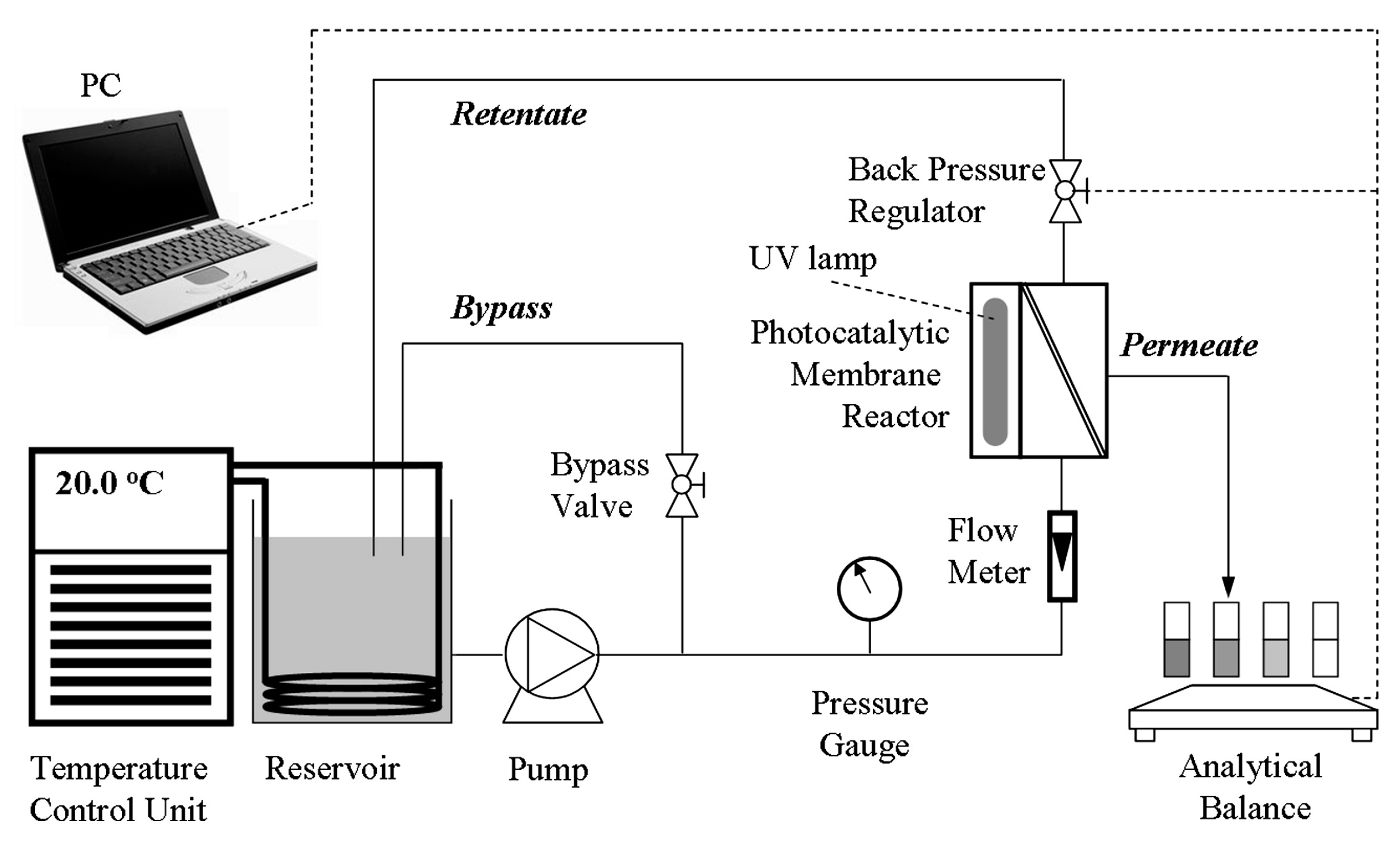
Figure 6.
Schematic diagram of a (a) primary; (b) improved continuous flow PMR with double-side active TiO2 modified membrane for water purification. Adapted with permission from [61,63], Copyright Elsevier, 2012.

Figure 7.
Schematic diagram of a typical split-type PMR with suspended photocatalyst utilizing nanofiltration. Adapted with permission from [65], Copyright Elsevier, 2014.
Figure 7.
Schematic diagram of a typical split-type PMR with suspended photocatalyst utilizing nanofiltration. Adapted with permission from [65], Copyright Elsevier, 2014.

Figure 8.
Schematic diagram of a split-type PMR with suspended photocatalyst. The UV lamps were placed in the feed tank as well as above the membrane unit. Adapted with permission from [68], Copyright Elsevier, 2008.
Figure 8.
Schematic diagram of a split-type PMR with suspended photocatalyst. The UV lamps were placed in the feed tank as well as above the membrane unit. Adapted with permission from [68], Copyright Elsevier, 2008.
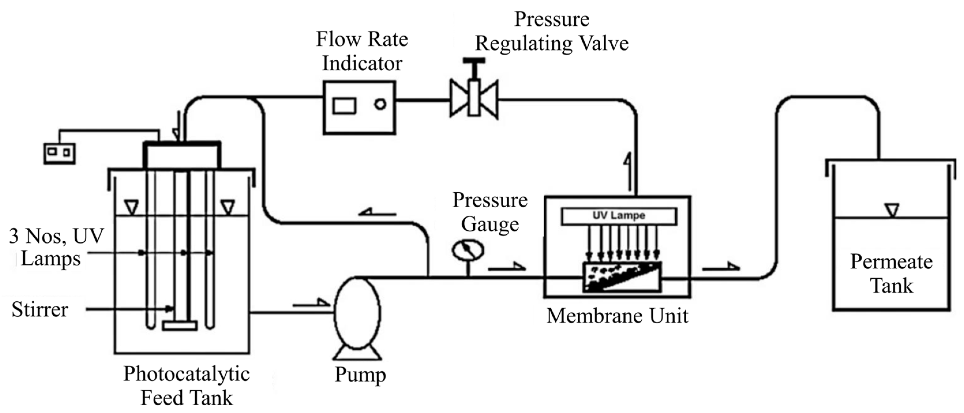
Figure 9.
(a) Schematic diagram and (b) front and side views of the pilot scale continuous PMR system. Adapted with permission from [70], Copyright Elsevier, 2016.
Figure 9.
(a) Schematic diagram and (b) front and side views of the pilot scale continuous PMR system. Adapted with permission from [70], Copyright Elsevier, 2016.
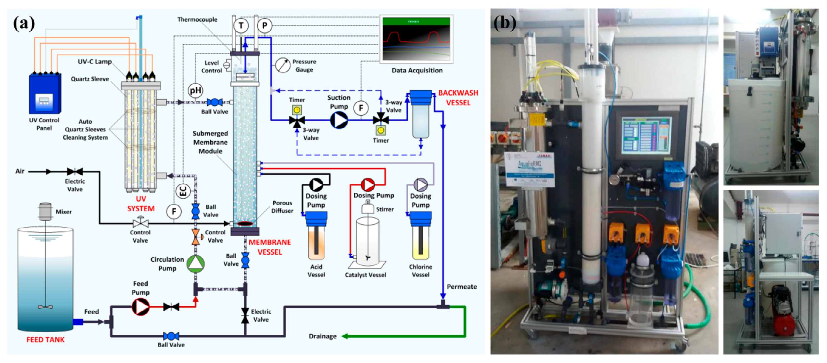
Figure 10.
Schematic diagram of a typical lab-scale integrative PMR with UV lamps inside the reactor. Adapted with permission from [73], Copyright Elsevier, 2006.
Figure 10.
Schematic diagram of a typical lab-scale integrative PMR with UV lamps inside the reactor. Adapted with permission from [73], Copyright Elsevier, 2006.

Figure 11.
Schematic diagram of a lab-scale integrative PMR with UV lamps outside the reactor. Adapted with permission from [77], Copyright Elsevier, 2014.
Figure 11.
Schematic diagram of a lab-scale integrative PMR with UV lamps outside the reactor. Adapted with permission from [77], Copyright Elsevier, 2014.

Figure 12.
Schematic diagram of a lab-scale hybrid PMR-DCMD system; TFin, TDin, TFout, TDout—thermometers for measurement of inlet and outlet temperatures of feed and distillate, respectively. Adapted with permission from [85], Copyright Elsevier, 2012.
Figure 12.
Schematic diagram of a lab-scale hybrid PMR-DCMD system; TFin, TDin, TFout, TDout—thermometers for measurement of inlet and outlet temperatures of feed and distillate, respectively. Adapted with permission from [85], Copyright Elsevier, 2012.

Figure 13.
Schematic diagram of the photocatalysis-dialysis system. (1) feed tank; (2) circulation pump; (3) flow meter; (4) pressure gauge; (5) membrane module; (6) photoreactor; (7) oxygen cylinder; (8) blocking valve; (9) magnetic stirrer and (10) cooling device. Adapted with permission from [90], Copyright Elsevier, 2007.
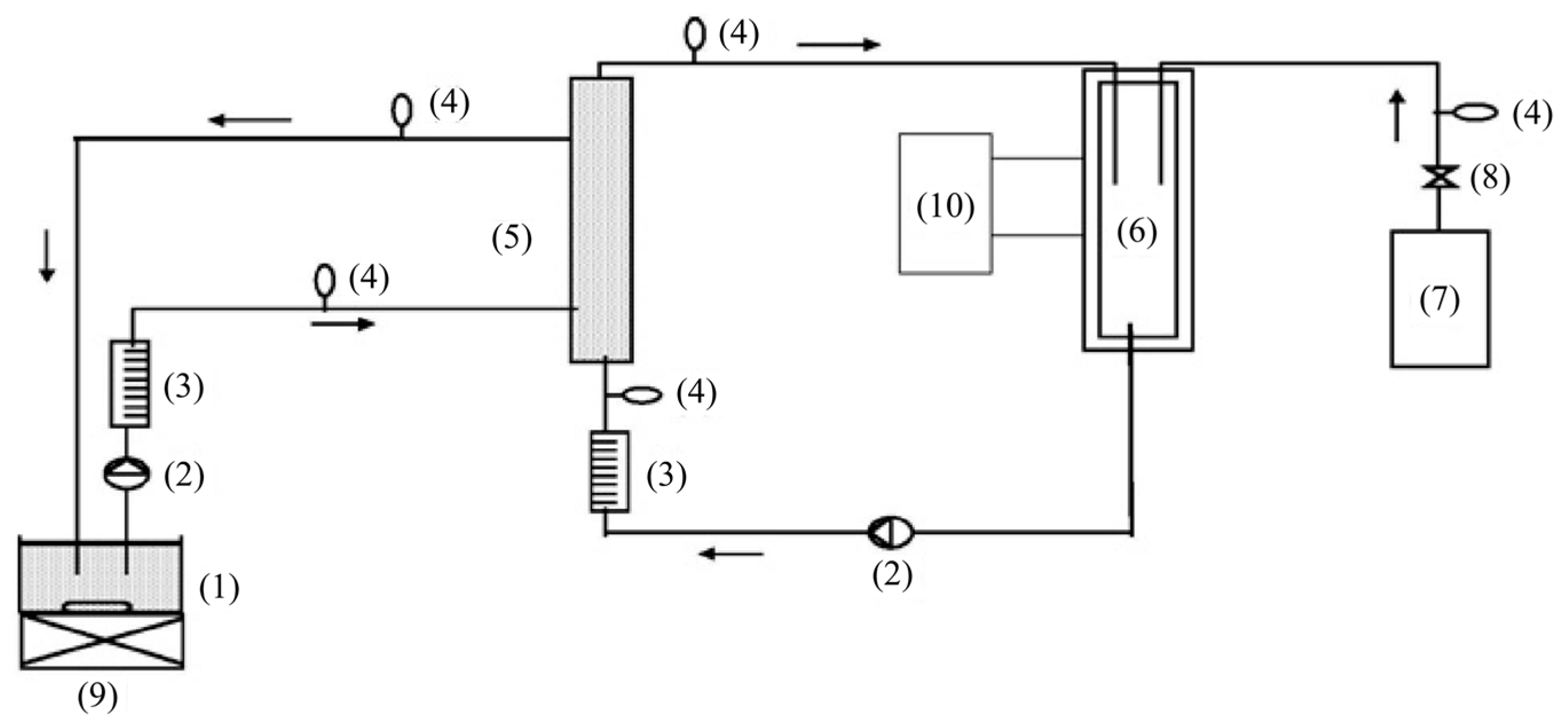

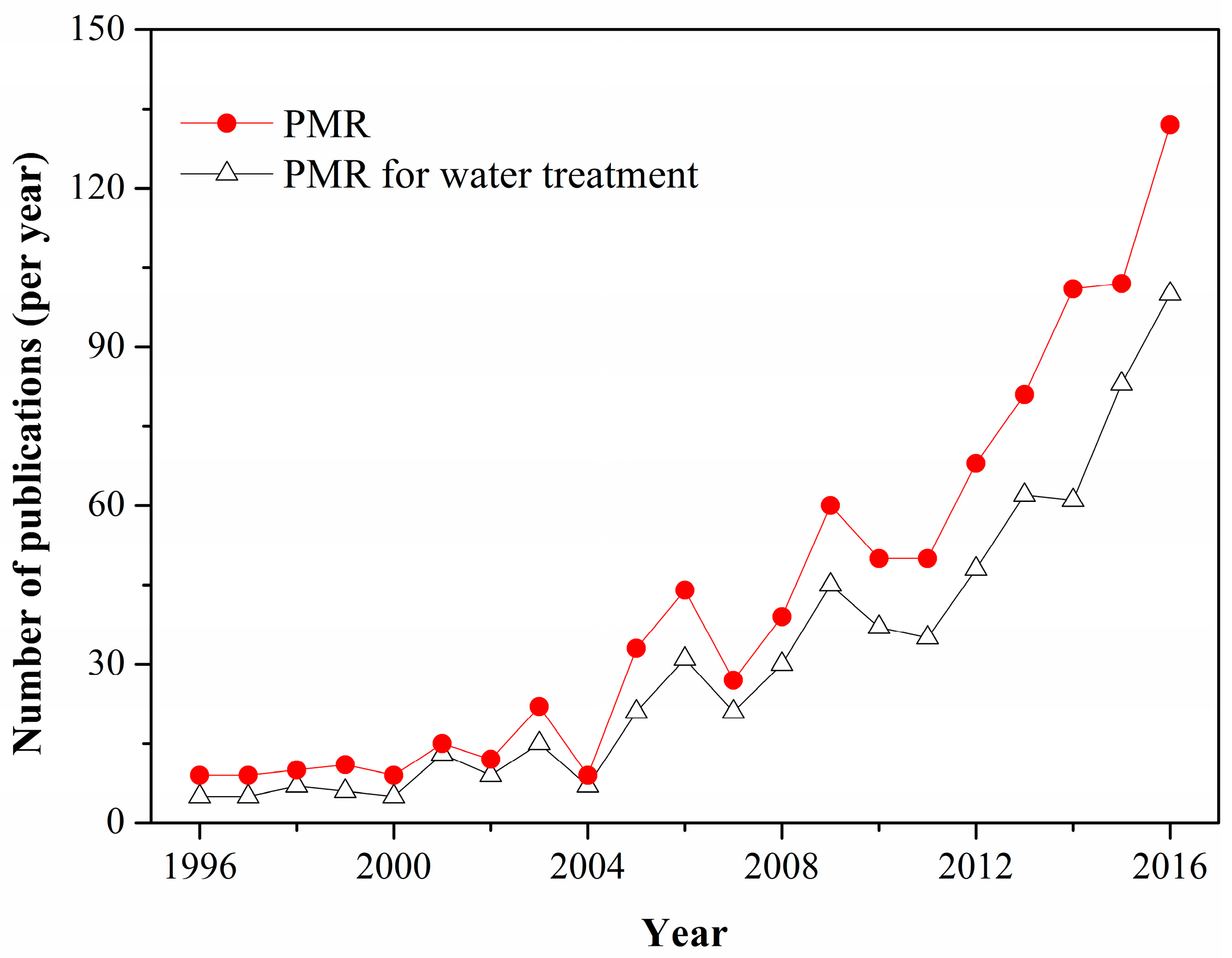
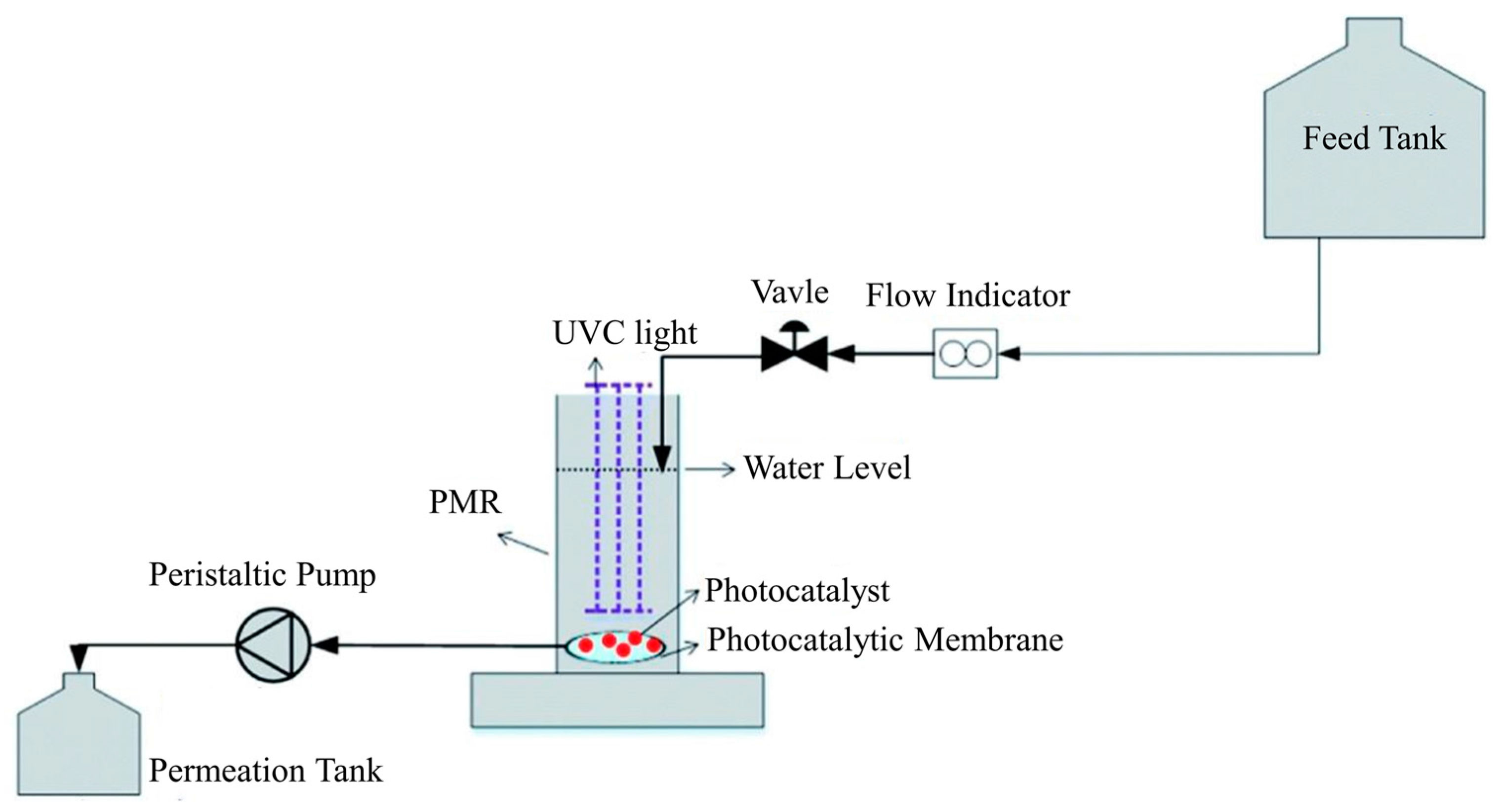
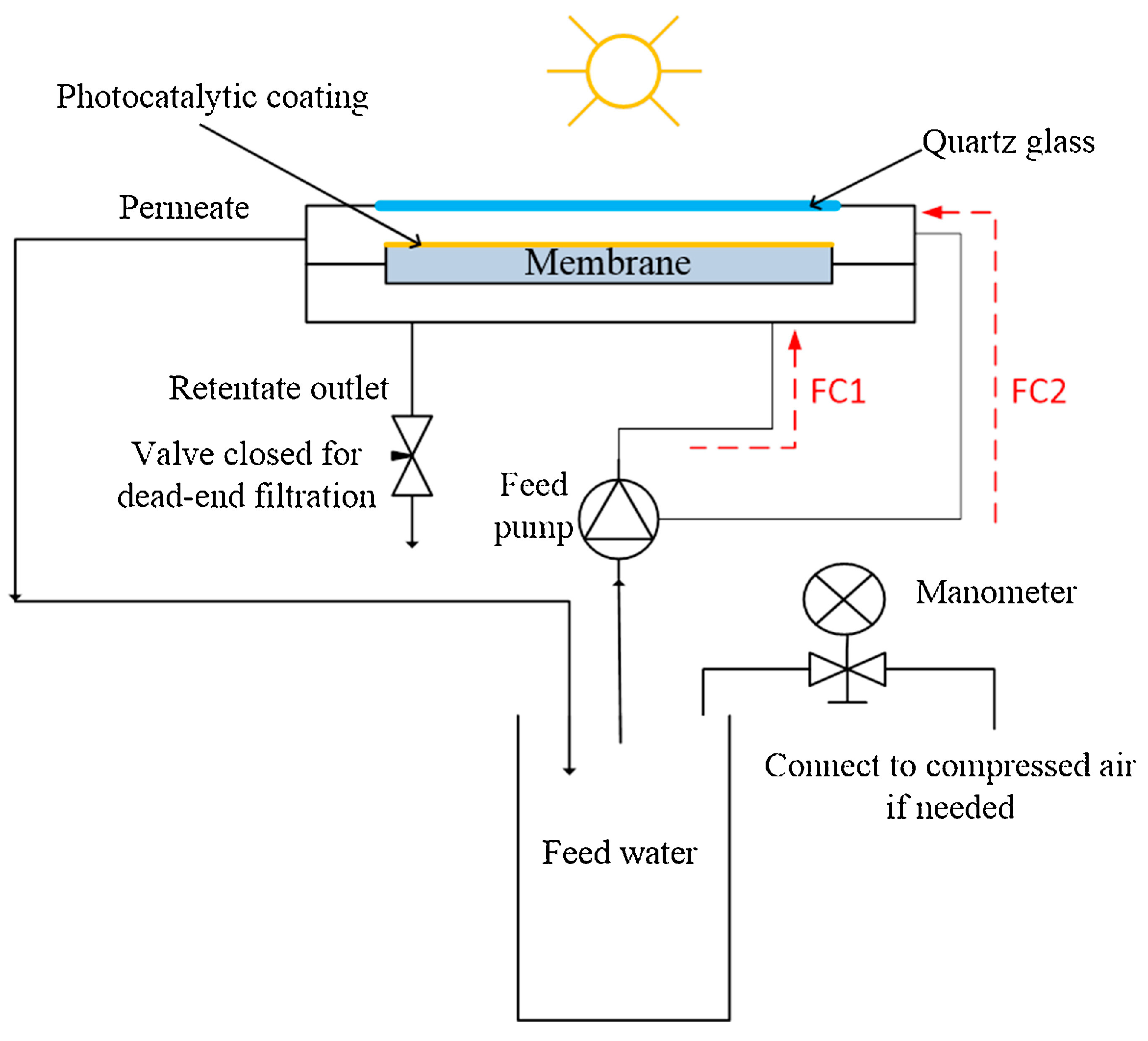
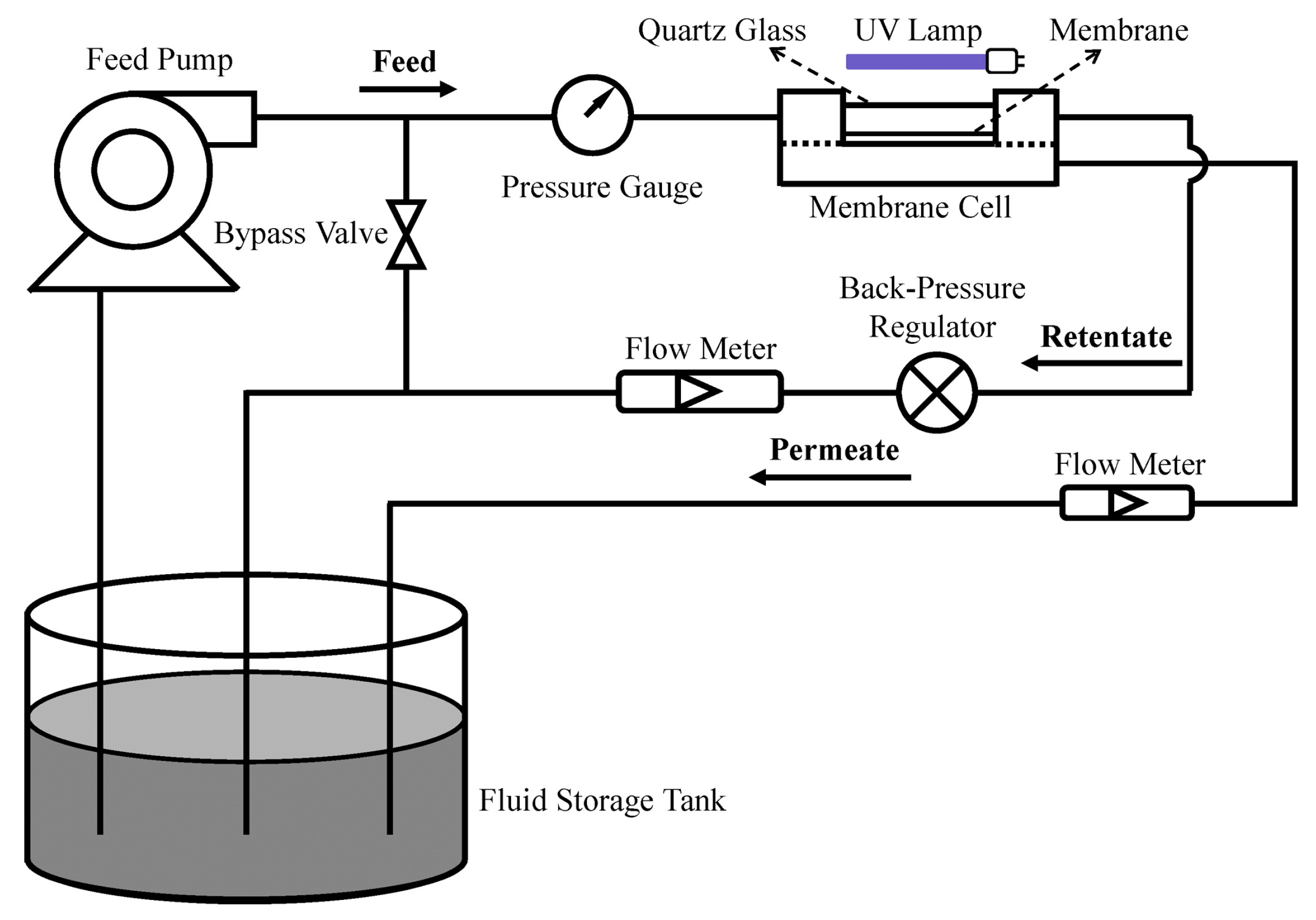
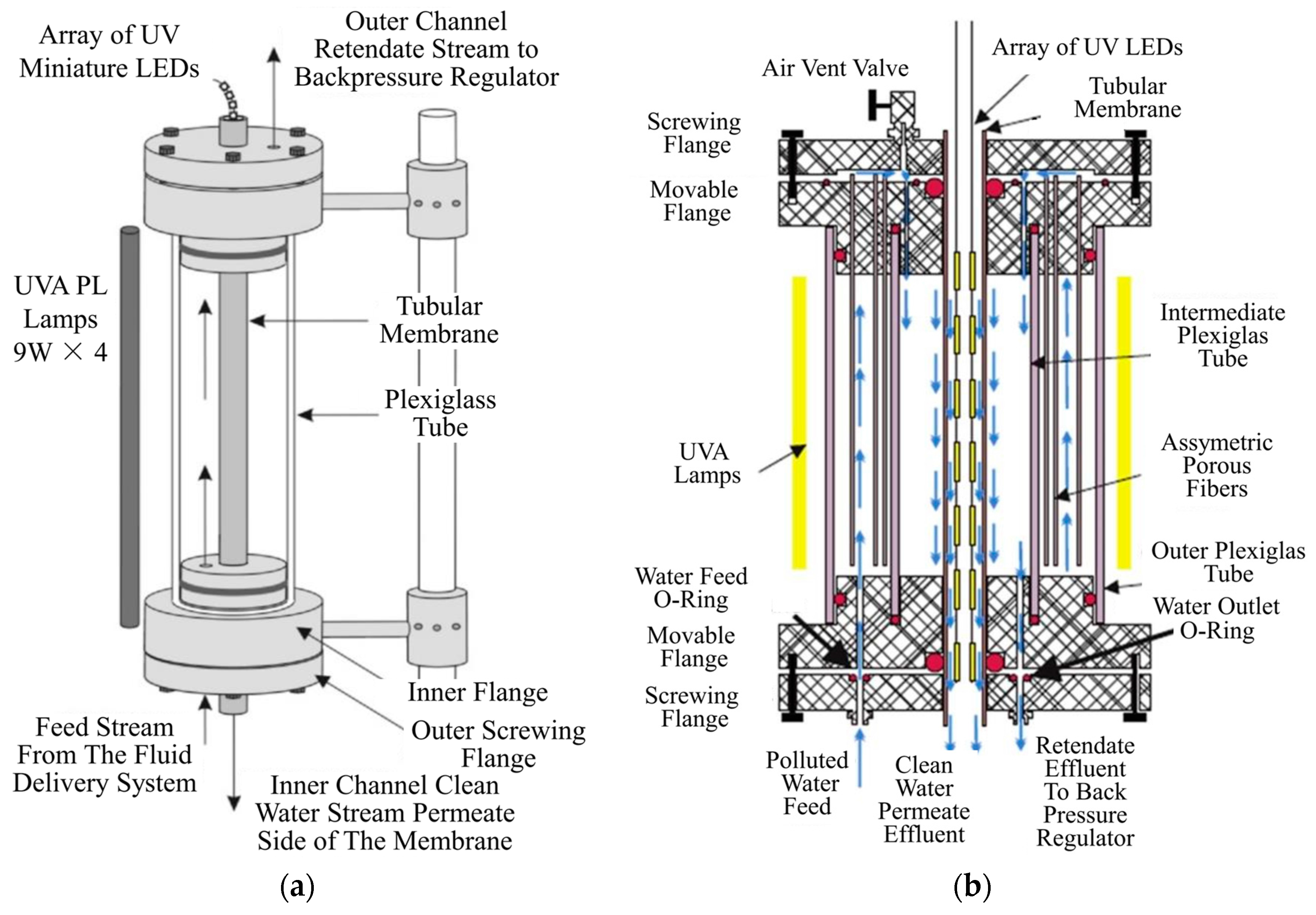
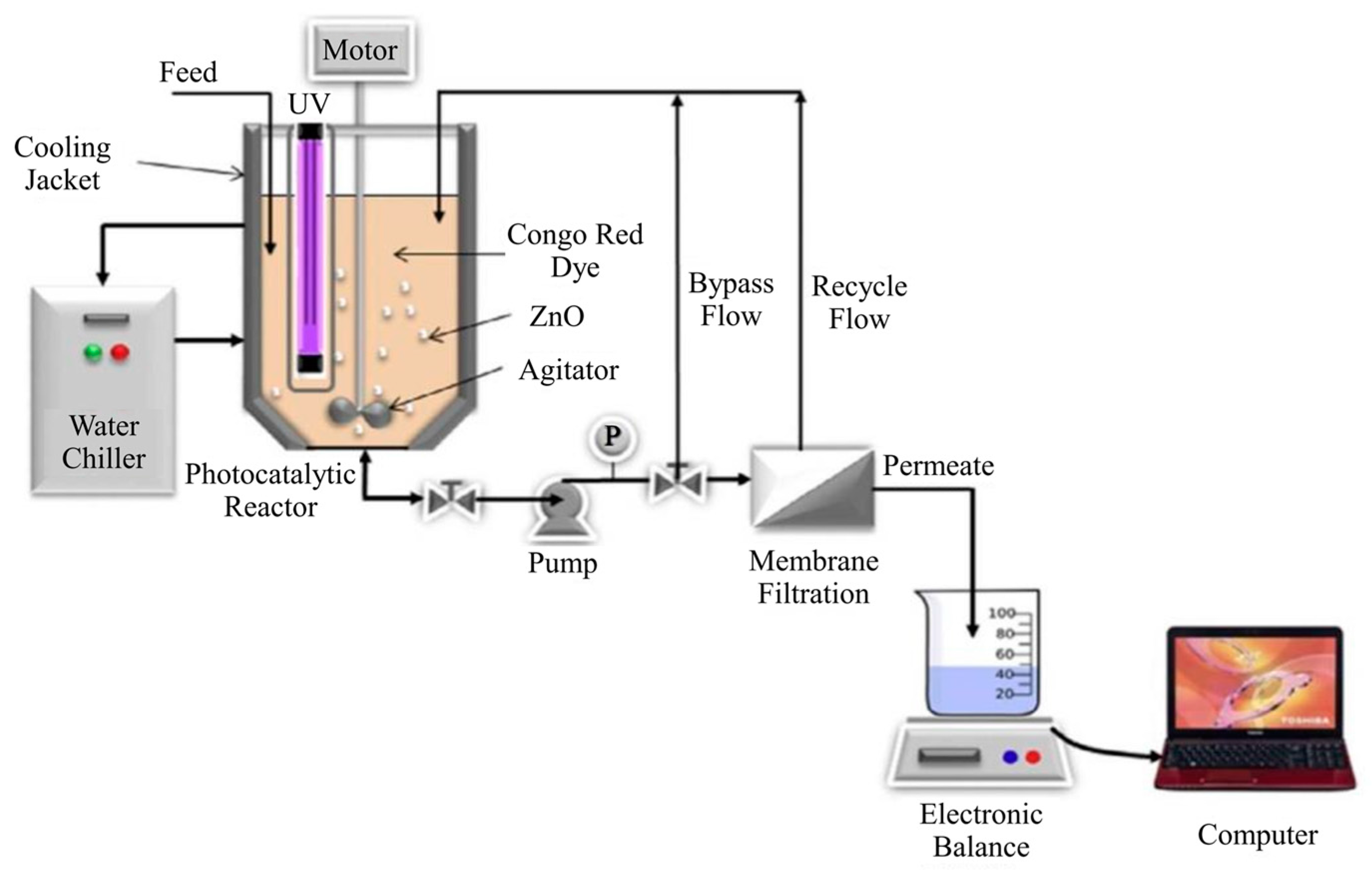
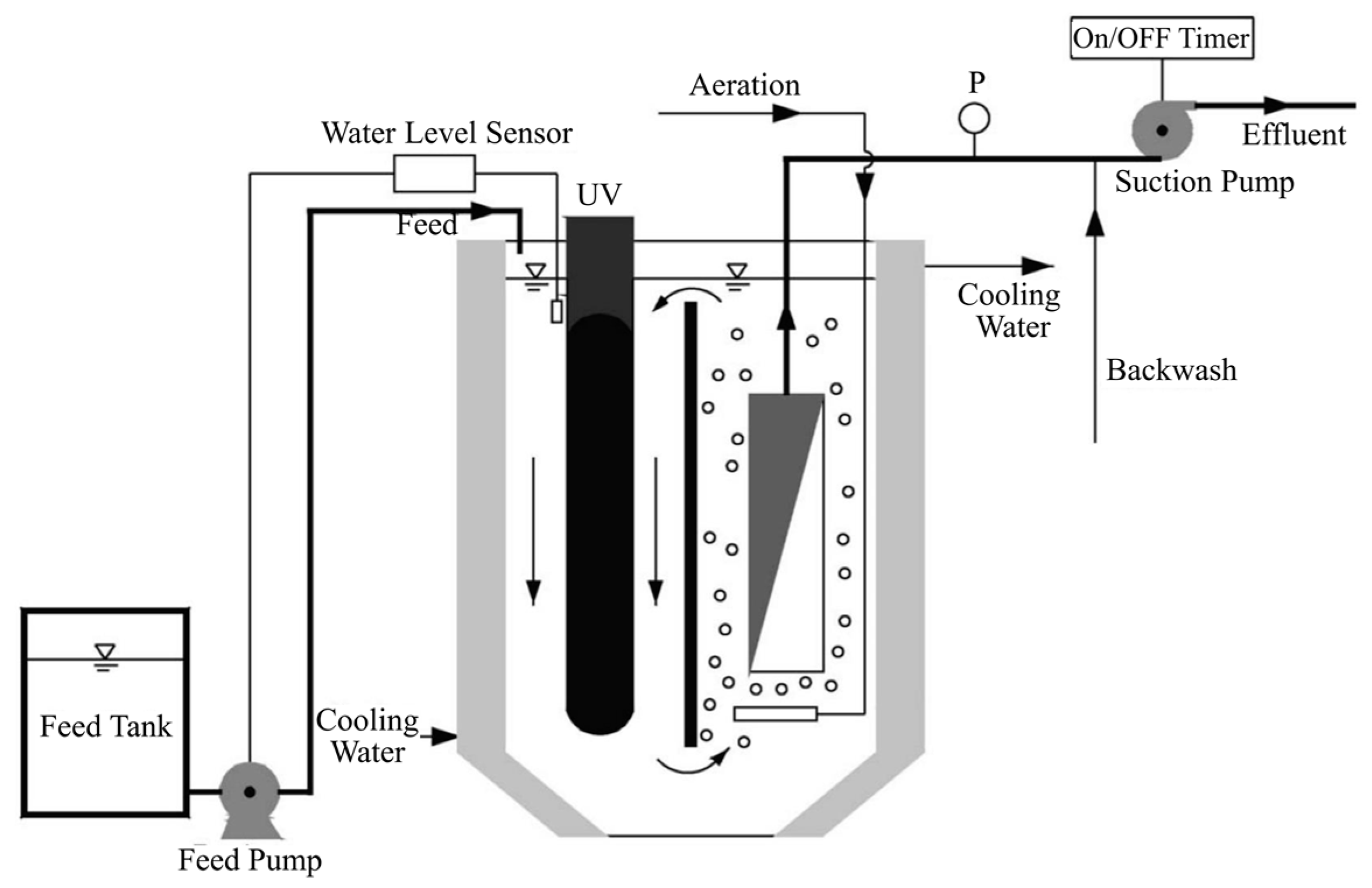
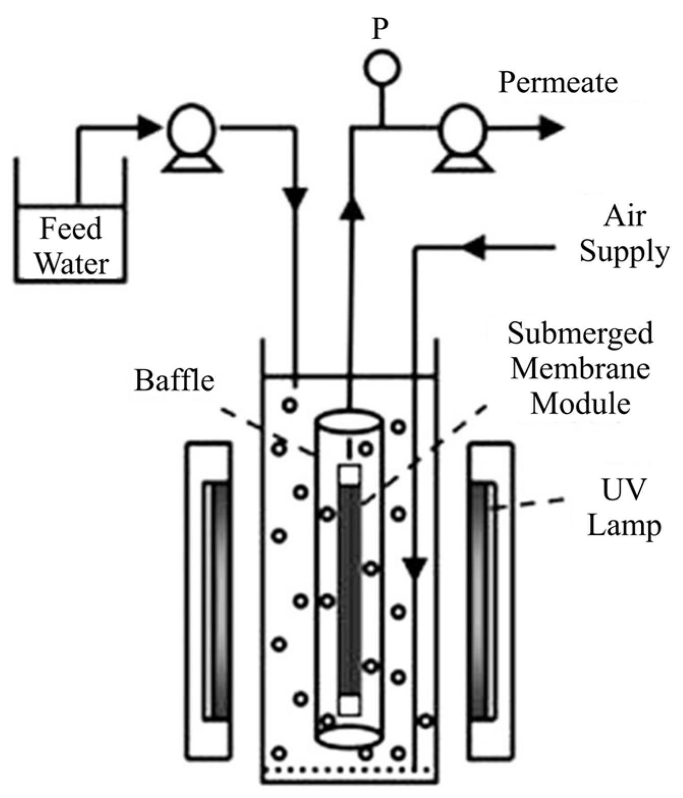
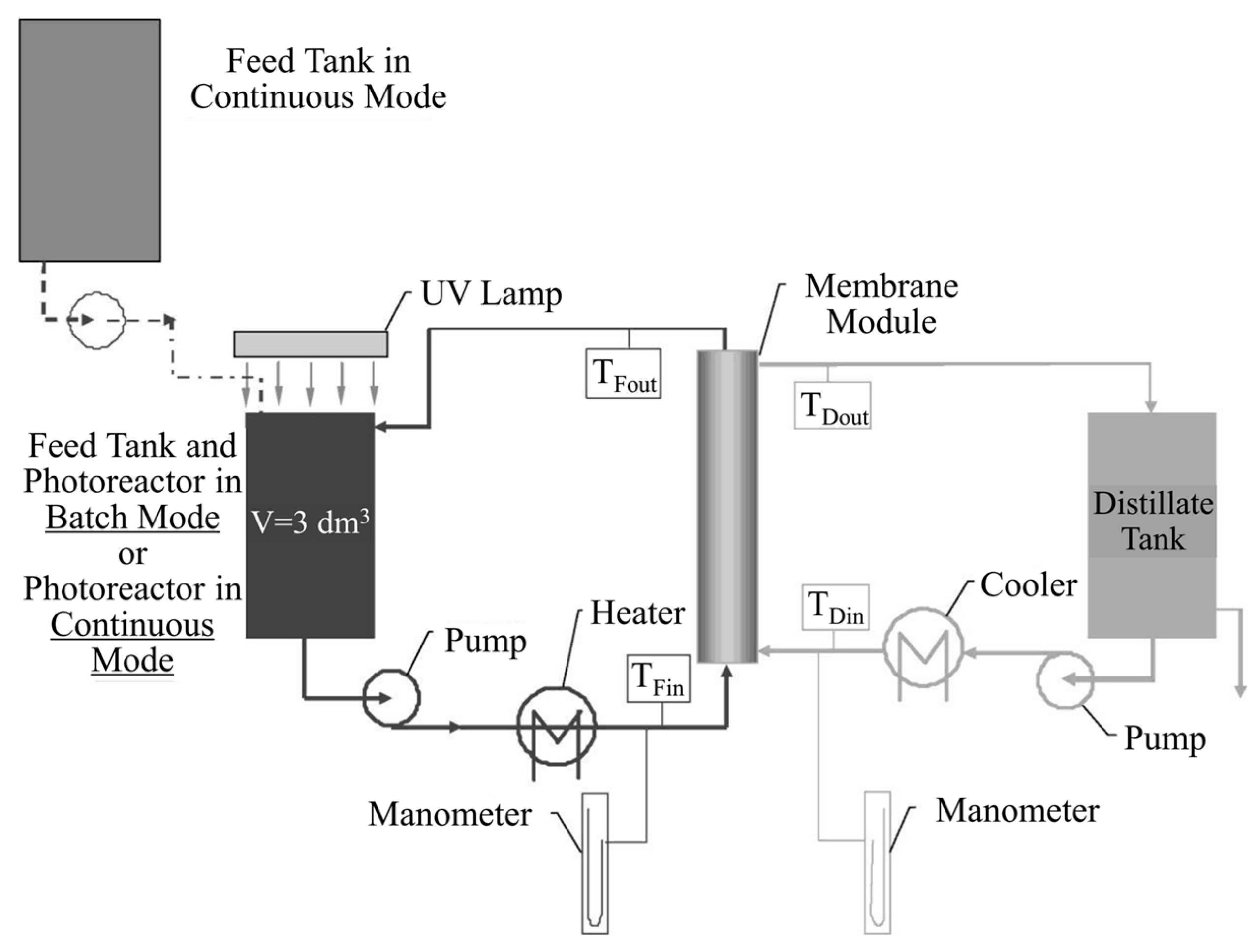
Table 1.
Examples of membranes coated with photocatalyst by different methods.
| Coating Method | Photocatalyst | Membrane | Characteristics | Ref. |
|---|---|---|---|---|
| Dip-coating | TiO2 nanoparticles | α-Al2O3 | TiO2-Al2O3 membrane was synthesized by dipping the α-Al2O3 disk into TiO2 sol. | [53] |
| Electrospraying TiO2 particles | TiO2 nanoparticles | Polyamide-6 nanofiber membrane | A colloid of TiO2 nanoparticles was added into the polyamide-6 solution before the electrospinning process. | [54] |
| Magnetron sputtering | TiO2 nanotubes | Polyethersulfone membrane | A titanium film was magnetron sputtered onto polyethersulfone membrane, and then anodized into TiO2 nanotubes. Subsequent crystallization of TiO2 to anatase structures was conducted at low temperatures. Enhanced photocatalytic performance was achieved by combining nanotubes with porous membrane. | [55] |
| Deposition of gas phase photocatalyst nanoparticles | TiO2 and Pt/TiO2 nano thin films | Glass fiber filters | TiO2 and Pt/TiO2 nanoparticles were prepared through flame spray pyrolysis, followed by expansion in a supersonic beam for the deposition on the glassfiber filters. | [56] |
Table 2.
Main advantages and disadvantages of PMRs with immobilized/suspended photocatalyst [23,32].
| PMR with Immobilized Photocatalyst | PMR with Suspended Photocatalyst | |
|---|---|---|
| Advantages |
|
|
| Disadvantages |
|
|
Table 3.
The optimum photocatalyst loading in different PMR systems.
| Configuration | Photocatalyst (Membrane) | Contaminant | Light Source | Tested Loading | Optimum Loading | Ref. |
|---|---|---|---|---|---|---|
| Immobilized | TiO2-porous stainless steel membrane | Methanol | UVA N/A | 0–34.0 g/m2 | 8.5 g/m2 | [98] |
| Immobilized | TiO2-ceramic membrane | Acid Red 4 | UVA 4 mW/cm2 | 0.03, 0.13, 0.29 and 0.44 g | 0.29 g | [99] |
| Immobilized | TiO2-PVDF membrane | Oily wastewater | UVA 0.333 mW/cm2 | 0–4 wt % | 2 wt % | [39] |
| Suspended | TiO2-P25 | Diclofenac | UVA 14.4 mW/cm2 | 0.3, 0.5 and 0.75 g/L | 0.5 g/L | [69] |
| Suspended | TiO2-P25 | Humic acids | UVC 0.154 mW/cm2 | 0.5, 1.0, 1.5 and 2.0 g/L | 1.5 g/L | [100] |
| Suspended | TiO2 | Acid Red 1 | UVC 62.91 mW/cm2 | 0–2 g/L | 0.5 g/L | [101] |
Table 4.
Optimal pH values attained in different PMR systems.
| Configuration | Photocatalyst (Membrane) | Contaminant | Tested pH Value | Optimum pH Value | Ref. |
|---|---|---|---|---|---|
| Suspended | TiO2-P25 | Diclofenac | 4.1, 6.2 and 7.5 | 6.2 | [69] |
| Suspended | TiO2-P25 | Humic acid | 3.0, 6.5 and 9.0 | 3.0 | [100] |
| Suspended | TiO2 | Fulvic acid | 3.4, 6.5, 8.2 and 10.3 | 3.4 | [73] |
| Immobilized | TiO2/Al2O3 membranes | Acid Orange 7 | 4.0, 6.0 and 8.0 | 4.0 | [106] |
| Suspended | TiO2-ZrO2 | Humic acid | 4.0, 7.0 and 10.0 | 4.0 | [107] |
Table 5.
Comparison of different kinds of membrane in application.
| Material | Configuration | Stability | Cost | Fouling | Surface Area |
|---|---|---|---|---|---|
| polymer | inside-out hollow fiber | normal | low | severe | large |
| polymer | outside-in hollow fiber | normal | low | normal | large |
| polymer | flat sheet | normal | low | normal | normal |
| ceramic | tubular | excellent | high | normal | normal |
© 2017 by the authors. Licensee MDPI, Basel, Switzerland. This article is an open access article distributed under the terms and conditions of the Creative Commons Attribution (CC BY) license (http://creativecommons.org/licenses/by/4.0/).
Share and Cite
MDPI and ACS Style
Zheng, X.; Shen, Z.-P.; Shi, L.; Cheng, R.; Yuan, D.-H. Photocatalytic Membrane Reactors (PMRs) in Water Treatment: Configurations and Influencing Factors. Catalysts 2017, 7, 224. https://doi.org/10.3390/catal7080224
AMA Style
Zheng X, Shen Z-P, Shi L, Cheng R, Yuan D-H. Photocatalytic Membrane Reactors (PMRs) in Water Treatment: Configurations and Influencing Factors. Catalysts. 2017; 7(8):224. https://doi.org/10.3390/catal7080224
Chicago/Turabian StyleZheng, Xiang, Zhi-Peng Shen, Lei Shi, Rong Cheng, and Dong-Hai Yuan. 2017. "Photocatalytic Membrane Reactors (PMRs) in Water Treatment: Configurations and Influencing Factors" Catalysts 7, no. 8: 224. https://doi.org/10.3390/catal7080224
Note that from the first issue of 2016, this journal uses article numbers instead of page numbers. See further details here.