Continuous-Flow Photocatalytic Degradation of Organics Using Modified TiO2 Nanocomposites


Department of Civil and Environmental Engineering, Hanyang University, 222 Wangsimni-ro, Seongdong-gu, Seoul 04763, Korea
*
Author to whom correspondence should be addressed.
Catalysts 2018, 8(2), 43; https://doi.org/10.3390/catal8020043
Submission received: 27 December 2017
/
Revised: 15 January 2018
/
Accepted: 21 January 2018
/
Published: 24 January 2018
Abstract
:In this study, TiO2 nanotubes (TNTs) were fabricated on a Ti sheet following the anodic oxidation method and were decorated with reduced graphene oxide (RGO), graphene oxide (GO), and bismuth (Bi) via electrodeposition. The surface morphologies, crystal structures, and compositions of the catalyst were characterized by field emission scanning electron microscopy, Auger electron spectroscopy, X-ray diffraction, photoluminance spectra, X-ray photoelectron spectroscopy, and energy dispersive X-ray spectroscopy. The TNTs loaded with RGO, GO, and Bi were used in a continuous-flow system as photocatalysts for the degradation of methylene blue (MB) dye. It was found that the TNTs are efficient photocatalysts for the removal of color from water; upon UV irradiation on TNTs, the MB removal ratio was ~89%. Moreover, the photocatalytic activities of the decorated TNTs were higher than that of pristine TNTs in visible light. In comparison with TNTs, the rate of MB removal in visible light was increased by a factor of 3.4, 3.2, and 2.9 using RGO-TNTs, Bi-TNTs, and GO-TNTs, respectively. The reusability of the catalysts were investigated, and their quantum efficiencies were also calculated. The cylindrical anodized TNTs were excellent photocatalysts for the degradation of organic pollutants. Thus, it was concluded that the continuous-flow photocatalytic reactor comprising TNTs and modified TNTs is suitable for treating wastewater in textile industries.
1. Introduction
TiO2 nanotubes (TNTs) synthesized via anodization have generated significant attention in recent years [1,2] because of their extraordinarily technological importance and improved photoelectric properties for a wide variety of applications such as solar cells [3], photocatalysis [4], gas sensors [5,6], water splitting [7,8], and developing functional surface devices [9]. Moreover, TiO2 decorated with reduced graphene oxide (RGO) [10], graphene oxide (GO) [11,12], and bismuth (Bi) [13] have been widely investigated owing to their lack of toxicity, high chemical stability, and capability of photooxidative destruction of most organic pollutants [14].
Bismuth has a good thermal conductivity and electrical resistance. These metallic properties are mostly important because they result in a high Fermi surface, a low effective mass, and the potential to induce a semiconductor transition [15]. Bismuth oxide is a p-type semiconducting material that has conduction band (CB) and valance band (VB) edges of +0.334 and +0.131 (vs. NHE), respectively [16]. Bismuth on the surface of TiO2 can trap photogenerated electrons, therefore reducing the recombination of electron and hole, and can improve the visible-light photocatalytic activity of TiO2 [17]. Graphene has attracted attention due to its thermal, mechanical, and electronic properties [18]. Graphene–TiO2 composites have improved efficiency in visible light, enhanced adsorption of contaminants on TiO2 surfaces, and reduced charge recombination [19].
Various high-efficiency TiO2-based heterogeneous photocatalysts, such as nanoparticles, nanofibers, nanowires, nanotubes, and nanorods, have been described as exhibiting high prospects for photocatalysts for the degradation of organic compounds. However, there are several practical problems that need to be addressed for the photocatalysts to be applied in in-situ wastewater treatment systems. For example, the use of TiO2-based nano-scale photocatalysts is limited because removing photocatalysts from the suspension is difficult and incurs additional costs. Furthermore, nano-structured TiO2 tends to aggregate easily, and suspensions are hard to operate in continuous-flow systems.
Nevertheless, several efforts have been made to reduce the abovementioned difficulties. Among various approaches described in previous studies, the immobilization of TiO2 particles on solid substrates is considered an effective and promising method because of the relative convenience and simplicity. Although, TiO2 particles immobilized on a solid substrates often show a low surface area. Moreover, disordered grain boundaries and arrangements discourage the transfer of photon-generated carriers. Thus, the efficiency of photocatalytic degradation of organic compounds over immobilized TiO2 particles is insufficient. As compared with immobilized TiO2 particles, TNTs possess a higher aspect ratio and a larger specific surface area, which suggest the fabrication and design of TNTs may be a more attractive and fruitful endeavor to achieve the photocatalytic degradation of organic compounds. In addition, the anodized TNTs can strongly bind to Ti foil, which is convenient for recycling TiO2 [20,21,22]. An easy separation of TNTs is preferred for the reuse of the catalyst in the continuous-flow photocatalytic treatment.
TNTs provide a decent channel for electron transfer and facilitate electron transport in the TiO2 photoelectrode. This is favorable for the light harvesting and transfer of photogenerated carriers. TNTs serve as flexible, supporting, and stable substrates and are more suitable for the design of photocatalytic reactors. They are used in a continuous-flow photocatalytic reactor. Therefore, it can be concluded that TNTs are promising candidates for the photodegradation of organic pollutants in a continuous-flow system. Thus, we prepared TNTs using the anodization technique and prepared their composites with RGO, GO, and Bi via electrodeposition. The photocatalytic activities of the TNTs loaded with RGO, GO, and Bi were explored systematically for degradation of methylene blue (MB) as a sacrificial agent in a continuous-flow photocatalytic reactor.
We developed a facile photocatalytic reactor composed of UV C and visible light sources. TNTs, GO-TNTs, RGO-TNTs, and Bi-TNTs were synthesized by the anodization method on Ti foil. The designed reactor was utilized for the photocatalytic degradation of MB. The degraded samples were analyzed using a UV-Vis spectrometer. Reusability tests of TNTs were performed to examine the stability of the photocatalyst, and quantum efficiency of the system was also evaluated. In our previous studies, we optimized the synthesis of nanomaterials on small lab-scale process (batch reactor: 35 mL capacity). The current study focused on a scale-up process using a continuous-flow reactor (1500 mL capacity) with a high production of nanomaterials. The continuous-flow reactor was found to be suitable for treating wastewater effluent in textile industries.
2. Results and Discussion
2.1. Characterization Results
2.1.1. Field Emission Scanning Electron Microscopy
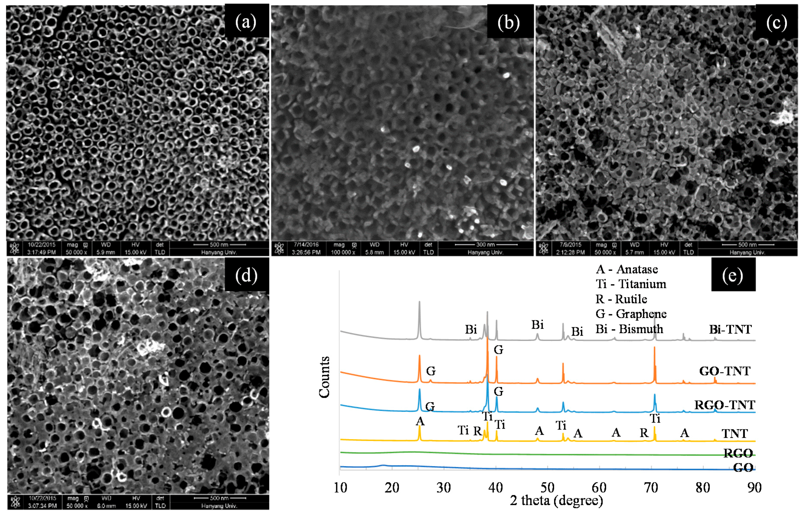
The structures and morphologies of the synthesized TNTs and modified TNTs were examined by field emission scanning electron microscopy (FESEM). Figure 1a displays the top view of pristine TNTs. It is evident that cylindrical nanotubes with an average inner diameter of 50–70 nm were formed on Ti foil by anodization [23]. The nanotube wall thickness was around 6–10 nm. It can be seen from the FESEM image of GO-TNTs (Figure 1b) that GO was attached on the surface of TiO2. The graphene sheet was not perfectly smooth, but showing roughness. TiO2 nanotubes can be seen situated below the graphene sheet. From surface morphology, it was observed that graphene was packed densely with TiO2 nanotube surfaces, showing a good composite of graphene–TiO2. RGO can be observed in Figure 1c with the anodized TiO2 nanotubes. The RGO at some parts is thicker as compared with other surface areas of the TiO2. Figure 1d displays the FESEM image of Bi-TNTs. Bi was composite on a TiO2 nanotube surface, but some of the surface area of the TiO2 nanotubes was filled by the Bi. RGO and Bi, as compared with the GO sheet, were not uniformly distributed on the surface of the TiO2.
2.1.2. X-ray Diffraction
The crystal structures of GO, RGO, TNTs, and modified TNTs were investigated using X-ray diffraction (XRD) as shown in Figure 1e. The main anatase TiO2 diffraction peaks were located at 25.36°, 48.13°, and 55°, corresponding to (101, (200), and (105) planes, respectively [24]. The rutile peaks were identified at 37.23° and 68.57°, and main Ti peaks were found at 35.10°, 41.10°, 53.98°, and 70.92°. XRD patterns of TNTs revealed that, after annealing at 550 °C, most of the Ti was converted into an anatase crystal structure, and some of it into a rutile crystal structure. The XRD spectra of RGO-TNTs and GO-TNTs composites showed graphene peaks together with the diffraction peaks of Ti, rutile, and anatase phases, as two graphene peaks of less intensity were detected at 26.3° [25] and 41.1° and overlapped with the Ti peak [26,27]. Regarding the XRD patterns of the GO powder, the GO peak shifted to around 17.1°, indicating that, after oxidation, the interlayer space increased. Regarding the RGO powder, due to the reduction, the peak of the GO disappeared, and another peak was observed at 24.0°. This may be due to the exfoliation of the layered GO structure [28]. In the XRD patterns of the Bi-TNTs composite, bismuth was present in a separate phase of bismuth oxide. The main bismuth peaks were observed at 27.4°, 47.1°, and 56.0° [17,29,30].
2.1.3. Energy Dispersive X-ray Spectroscopy
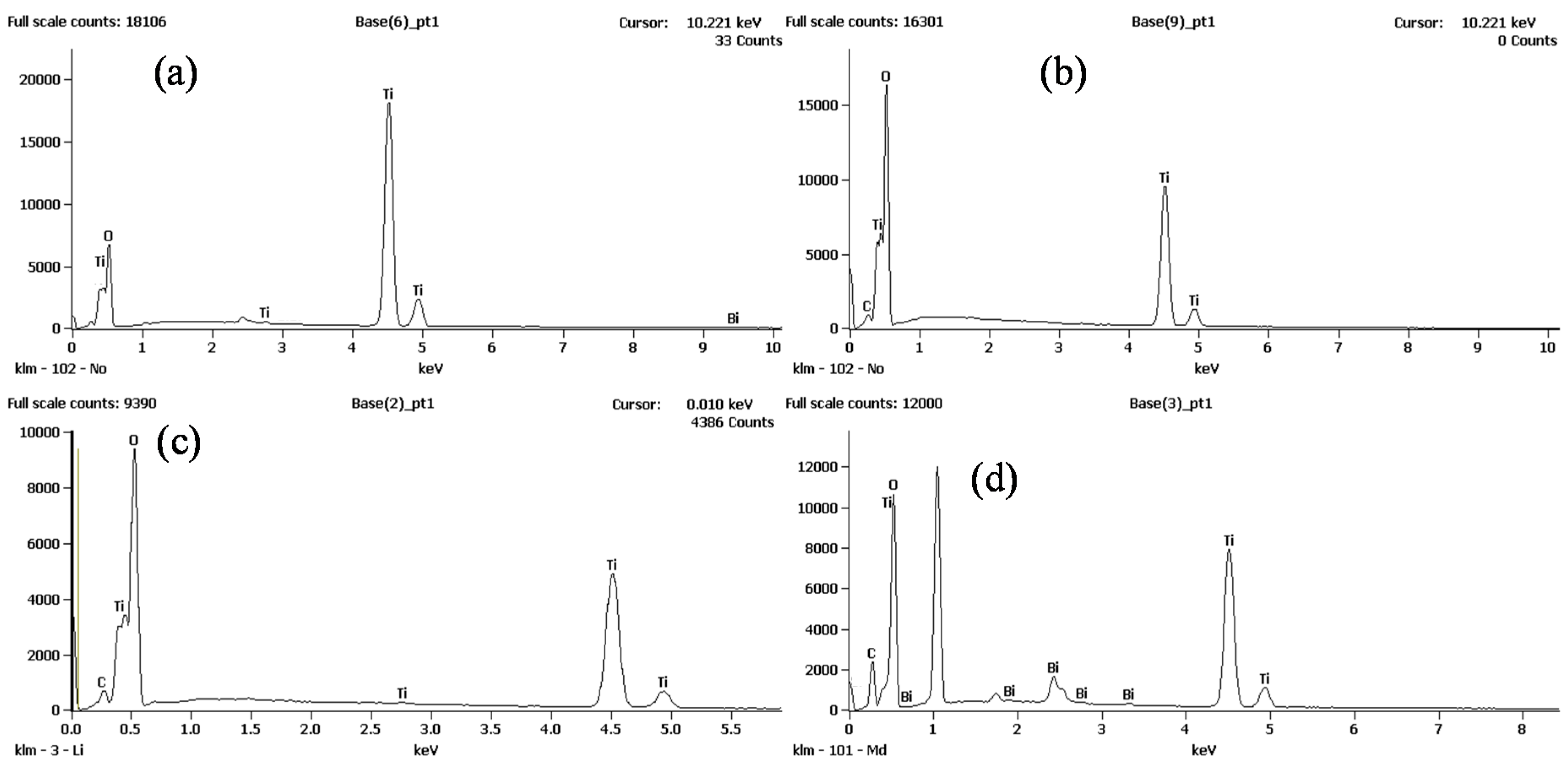
The elemental composition of TNTs, GO-TNTs, RGO-TNTs, and Bi-TNTs composites was achieved using energy dispersive X-ray spectroscopy (EDX) as shown in Figure 2. In EDX spectrum of TNTs (Figure 2a), Ti and oxygen peaks were detected. In GO-TNTs and RGO-TNTs, carbon peaks were also observed together with Ti and oxygen peaks as shown in Figure 2b,c, respectively. In the EDX spectrum of Bi-TNTs (Figure 2d), the deposit was mostly comprised of bismuth [31,32]. These EDX results correspond to Section 2.1.4 and Section 2.1.6.
2.1.4. Auger Electron Spectroscopy
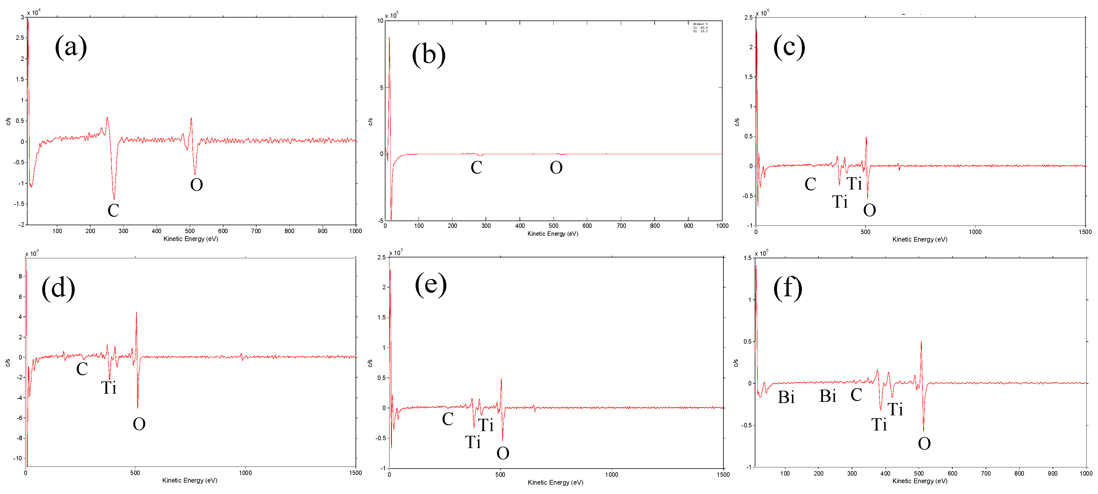
Elemental and atomic compositions of the GO, RGO, TNTs, and modified TNTs were determined by Auger electron spectroscopy (AES), as shown in Figure 3. The AES atomic composition of GO, RGO, TNTs, and modified TNTs is presented in Table 1. In TNTs and modified TNTs, the atomic concentration of oxygen was high, because Ti and Bi were mostly converted in oxides. The AES atomic spectra of GO, RGO, TNTs, and modified TNTs contain Ti, C, Bi, and O peaks (Figure 3a–f). The AES spectrum of GO and RGO shows C and O peaks as shown in Figure 3a,b, respectively. For TNTs, Ti peaks were observed together with O and C peaks (Figure 3c). Graphene as carbon peaks can be seen in the AES spectra of GO-TNTs and RGO-TNTs as shown in Figure 3d,e, respectively, while Bi-TNTs contain bi peaks (Figure 3f). This can be confirmed from AES results, which show that RGO, Bi, and GO were effectively composite on the surfaces of anodized TNTs.
2.1.5. Photoluminescence Spectroscopy
Photoluminescence (PL) spectra of pure TNTs, GO-TNTs, Bi-TNTs, and RGO-TNTs (Figure 4a) were obtained to examine their excited states. The emissions were monitored in a single scan mode from 300 to 800 nm. The excitation wavelength was 325 nm using an He–Cd laser. The PL intensities of the semiconductor materials were affected by the recombination rates of photo-induced electrons (e−) and holes (h+). A lower PL intensity indicated an improved charge separation of e− and h+ [33]. A lower PL intensity was examined for the modified TNTs in contrast to that of the pristine TNTs in Figure 4a. This result could be attributed to the composite of Bi, GO, and RGO with TiO2, since graphene acted as an e− transportation layer for TiO2 to reduce charge recombination. This reduction enhanced the charge separation efficiency, which improved the overall efficiency of the photocatalytic process.
2.1.6. X-ray Photoelectron Spectroscopy
Figure 4b shows the full spectrum of X-ray photoelectron spectroscopy (XPS) of GO, RGO, TNTs, RGO-TNTs, GO-TNTs, and Bi-TNTs composites. C 1s and O 1s peaks were detected for GO and RGO samples. C 1s peak at binding energy of 283 eV was assigned to a C–C bond. The O 1s peak at a binding energy of 530 eV was related to the C–O functional group. TNTs and graphene–TNTs composites had a Ti 2p peak together with C 1s and O 1s peaks. The Ti 2p peak at a binding energy of 464 eV corresponded to Ti 2p1/2. Bi 4f peaks were detected at binding energies of 159 eV and 164 eV belonging to Bi 4f7/2 and Bi 4f5/2 regions, which could be determined as bismuth oxide [34,35]. No Ti–C or Ti–Bi bonds were detected, which indicates that graphene and Bi elements did not enter the TiO2 lattice. According to XPS analysis, the fabricated catalysts were composites.
2.2. Photocatalytic Degradation in Continuous-Flow Treatment
2.2.1. Photocatalytic Degradation under UV C Light
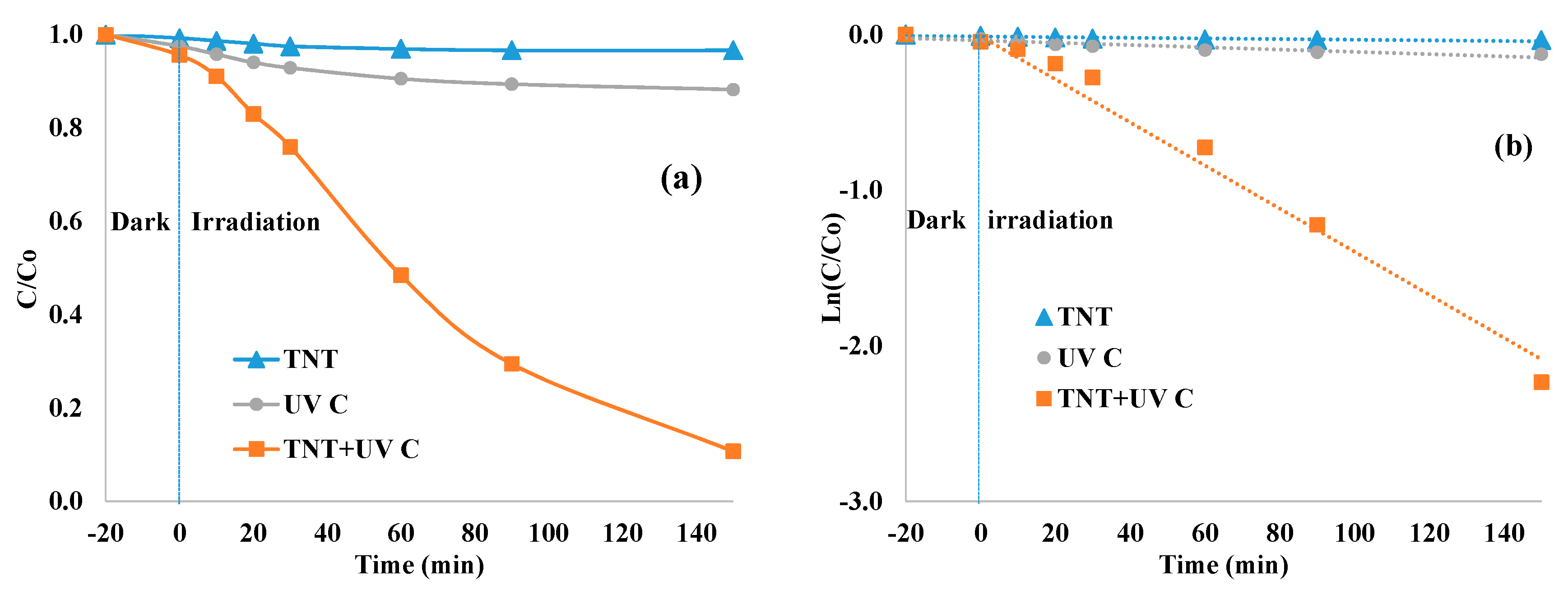
To estimate the photocatalytic degradation of MB dye using TNTs and composites, a continuous-flow test was carried out. Figure 5 displays the photodegradation rate of MB dye over TNTs, UV C, and TNTs + UV C light. Before the start of the experiment, the catalyst was placed in the dark for 20 min to achieve sufficient adsorption. Almost no MB degradation was found when the experiment was performed using only TNTs (in the dark). This control experiment proved that TiO2 requires a light source for its activation to degrade the pollutant. Almost 12% MB degradation was observed when the experiment was performed using only UV C light (without TNTs). For continuous-flow treatment using TNTs + UV C light, the extent of MB degradation was 89% at a hydraulic retention time (HRT) of 150 min.
2.2.2. Photocatalytic Degradation under Visible Light
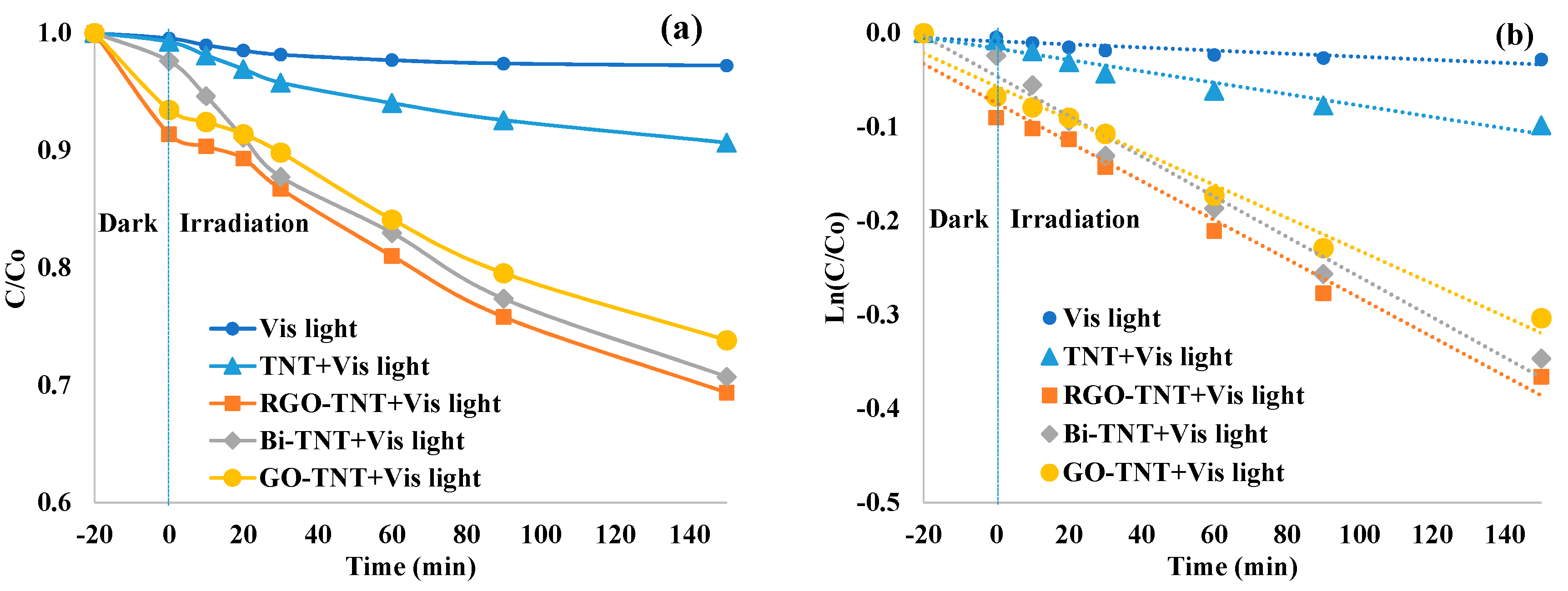
The degradation of MB was also evaluated using TNTs and modified TNTs under visible light using a continuous-flow photocatalytic reactor. Figure 6 shows the degradation rate of the MB dye over Vis light, TNTs + Vis light, RGO-TNTs + Vis light, Bi-TNTs + Vis light, and GO-TNTs + Vis light at an HRT of 150 min. Before the start of the experiment, the catalyst was placed in a dark solution for 20 min to achieve sufficient adsorption. Graphene–TiO2 composites show MB dye adsorption up to 10%, as in previous studies it was observed that graphene metal oxide compounds can adsorb dyes before any photocatalytic degradation [36,37]. The synergic effect of dye adsorption on photocatalytic activity of graphene–TiO2 composites is due to the strong π connection of graphene surface [38]. Almost no MB degradation was observed when the experiment was performed using only visible light (without TNTs). The MB degradation rates achieved by using TNT + Vis light, RGO-TNTs + Vis light, Bi-TNTs + Vis light, and GO-TNTs + Vis light were 9%, 31%, 29%, and 26%, respectively. In comparison with pristine TNTs under visible light, the degradation of MB increased by a factor of 3.4, 3.2, and 2.9 using RGO-TNTs, Bi-TNTs, and GO-TNTs, respectively.
The first order reaction rate constants were estimated using Equation (1):
where C is the concentration of MB dye at a specific time, C0 is the initial MB dye concentration, k is the pseudo first order reaction rate constant (h−1), and t is the reaction time (h). Table 2 displays a summary of first order reaction rate constant k values and R2 values. The continuous-flow experiments for TNTs + UV C light gave a reaction rate constant of 0.893 h−1. The continuous-flow experiments using RGO-TNTs + Vis light had the highest reaction rate constant (0.146 h−1) compared to other catalysts employed under the same conditions.
ln(C/C0) = −k t
The higher visible light photocatalytic efficiency of the modified TNTs may be due to the following. The RGO-, Bi-, and GO-TNT composites reduce the band gap and increase the absorption of TiO2 under visible light irradiation [39,40]. In GO-TNT and RGO-TNT catalysts, graphene acts as an e− transporting layer for CB of TiO2 and reduces charge recombination. In the Bi-TNT catalyst, the Bi composite on the surface of TiO2 can trap photo-generated electrons; as Bi has a positive charge on its surface, it can capture and immobilize electrons and thereby reduce the recombination of e− and h+ [41]. This process promotes the formation of OH radicals and superoxides. Studies have revealed that the self-organized photocatalytic system of TNTs can efficiently degrade the MB dye. Hence, a continuous-flow reactor based on a TNT photocatalyst is suitable for treating wastewater effluent in textile industries.
2.3. Reusability Test
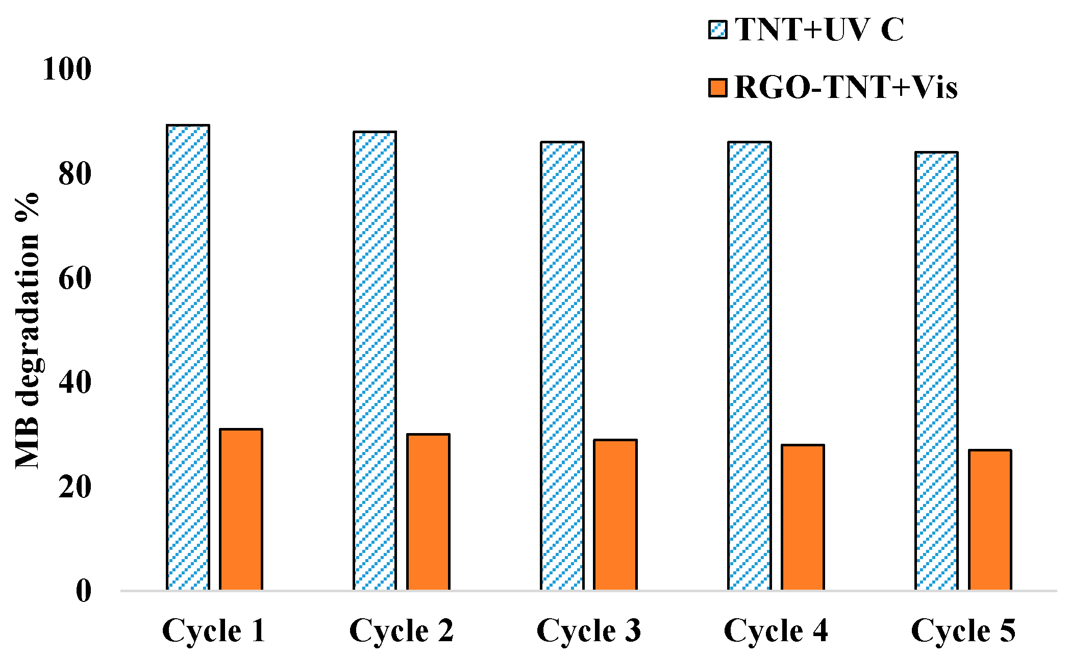
The recycling of TNTs + UV C and RGO-TNTs + Vis light was performed to examine the stability of the catalysts (Figure 7). Recycling experimental conditions were the same as those for the continuous-flow experiment. After each cycle, the catalyst was washed in DI water and dried to remove any deposits from the surface. Recycling results indicated that the both catalysts were stable for five catalytic cycles. The MB degradation efficiency dropped to only 5% and 4% for TNTs + UV C and RGO-TNTs + Vis light, respectively. Furthermore, TNTs + UV C showed a higher MB removal efficiency because of the use of UV C light. We are working on enhancing the photocatalytic activity of the continuous-flow system under visible light.
2.4. Calculation of Quantum Efficiencies
In a photocatalytic system, the quantum efficiency can be defined as the ratio of the number of pollutant molecules degraded during a given time t to the total number of photons absorbed by the catalyst to be activated [42]. The quantum efficiencies of the photocatalytic reactor with TNTs + UV C and RGO-TNTs + Vis lights were calculated separately, as shown in Table 3. The quantum efficiency of the reactors with TNTs + UV C and RGO-TNTs + Vis lights were 9.11 × 10⁻⁵ and 3.22 × 10–5 MB molecule photon−1, respectively. The quantum efficiency of this system is low compared with those of other studies [43], so we are working on improving the quantum efficiency of the continuous-flow system. In this study, we scaled up the process using a continuous-flow mode for the treatment of industrial wastewater with a high production of nanomaterials. In future work (which is in progress), we will take cost calculations into account.
3. Materials and Methods
3.1. Chemicals and Materials
All chemical reagents were used without further purification and purchased from commercial sources. Ti foil (purity 99.5%, size 4 × 5 cm2, and thickness 0.25 mm) was obtained from Ti-Shop.com, London, UK. Graphite powder (99.99%) was purchased from Alfa Aesar, Seoul, Korea. Bismuth nitrate (98.0%), ethylene glycol (94.5%), sodium nitrate (>99.0%), hydrazine monohydrate (>80.0%), and sulfuric acid (98.1%) were purchased from Daejung Chemicals & Metal Co. Ltd., Shiheung, Korea. Ammonium fluoride (97.0%) was purchased from Junsei Chemical Co. Ltd., Tokyo, Japan.
3.2. Synthesis of the Catalysts
3.2.1. Synthesis of GO and RGO
GO was made using modified Hummer’s method [44]. Initially, graphite powder (1 g), sodium nitrate (0.5 g), and sulfuric acid (25 mL) were stirred together for 1 h. Then, potassium permanganate (3 g) was added and stirred further for 10 h at 40 °C. The brown-colored GO solution was obtained and washed five times with hydrochloric acid (1 M) and deionized (DI) water, and subsequently vacuum dried at 60 °C. To prepare RGO, DI water (100 mL) and GO powder (0.1 g) were sonicated. Hydrazine monohydrate (1 mL) was then added, and the mixture was dried at 100 °C for 10 h. The obtained RGO was washed in DI water and vacuum-dried at 50 °C.
3.2.2. Synthesis of GO-TNT
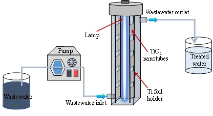
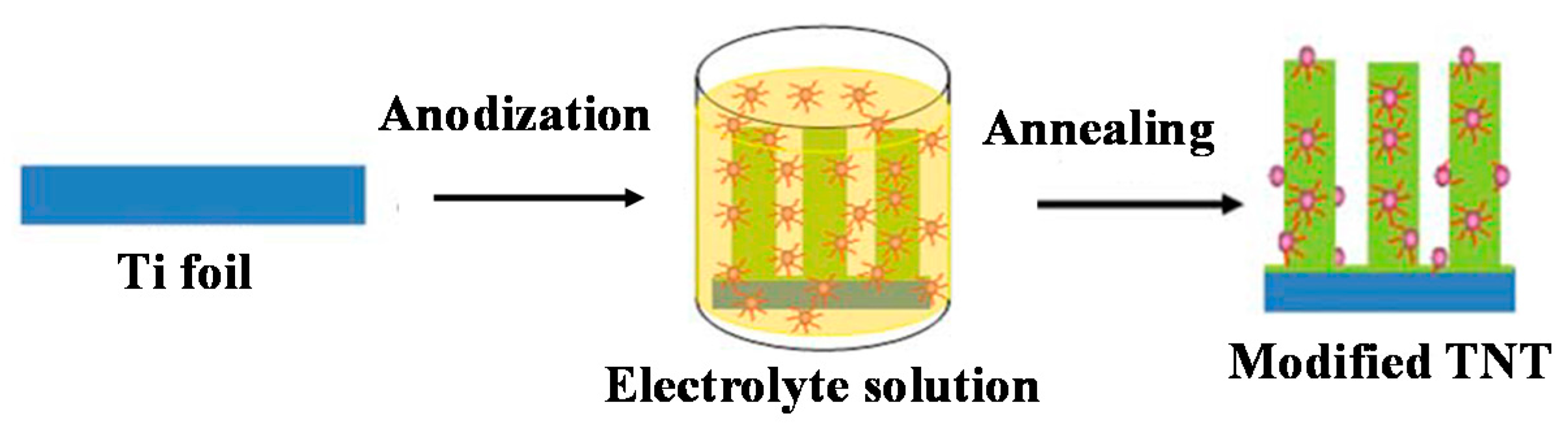
The one-step synthesis of GO-TNTs was performed as described in our previous work [45]. For all experiments, as an initial step, Ti foil was sonicated (for 10 min each) in acetone, ethanol, and DI water to remove impurities and then dried in N2. The electrolyte solution was prepared from ethylene glycol (EG) (94 wt %), DI water (5 wt %) together with ammonium fluoride (1 wt %), and GO (0.25 g L−1). For all experiments, Ti foil was used as the working electrode (anode), and a platinum mesh was used as the counter electrode (cathode) at a distance of 2 cm. Anodization was performed at 48 V for 2 h using an N6702A power supply (Agilent Technologies, Madrid, Spain), as shown in Figure 8. After anodization, Ti foil was rinsed using DI water and dried in N2. In order to enhance the crystalline structure of TiO2, annealing was achieved at 550 °C for 90 min in a furnace for all experiments.
3.2.3. Synthesis of RGO-TNT
The one-step fabrication of RGO-TNTs was performed as described in our previous work [46]. The electrolyte solution was EG (94 wt %), DI water (5 wt %), and NH4F (1 wt %) with 0.5 g L−1 of RGO. Anodization was achieved at 48 V for 2 h. After anodization, the Ti foil was rinsed in DI water and dried using N2. Annealing was performed at 550 °C for 90 min.
3.2.4. Synthesis of Bi-TNT
The one-step fabrication of Bi-TNTs was achieved in accordance with our previous report [47]. An electrolyte comprised of EG, NH4F, DI water, and 1 wt % bismuth nitrate was utilized for this purpose. Anodization was achieved at a voltage of 40 V for 2 h. After anodization, the Ti foil was washed using DI water and dried in N2. Annealing was performed at 550 °C for 90 min.
3.3. Characterization
The surface morphologies of the catalysts were studied by FE-SEM, Sigma, Carl Zeiss Co., Oberkochen, Germany. The crystal structure was examined by XRD, D8-Advance, Bruker-AXS Co., Karlsruhe, Germany. The elemental analyses were performed using AES 700, PHI 700 xi (Physical Electronics, Inc., Chanhassen, MN, USA). The excited state of catalyst was evaluated by Micro Confocal PL, Mono Ra 750i (DongWoo Optron Co., Ltd., Gwangju, South Korea). The examination of chemical composition of the composites were determined with EDX, Noran System 7, Thermo Scientific, Waltham, MA, USA, and XPS, Thermo Fisher Scientific Co., Bartlesville, OK, USA.
3.4. Continuous-Flow Photocatalytic Experiment
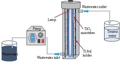
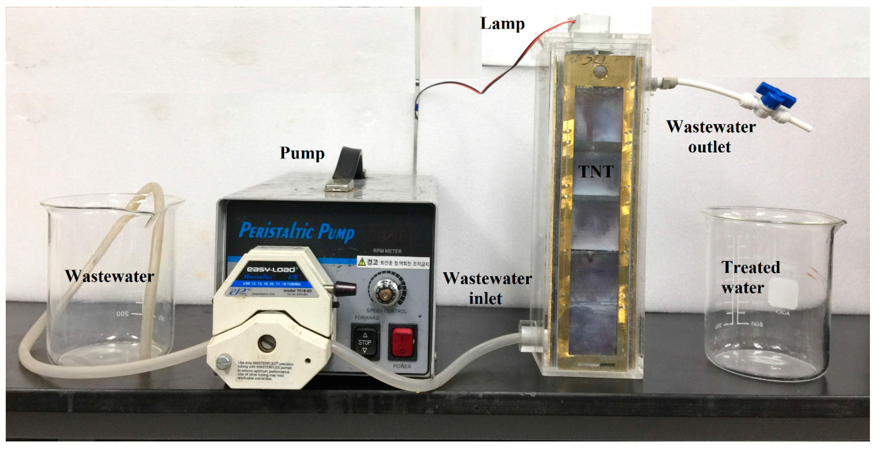
In order to examine the photocatalytic degradation of MB solution by TNTs and modified TNTs, a continuous-flow photocatalytic reactor was designed on a laboratory scale, as shown in Figure 9. The light sources were a UV C fluorescent lamp (16 W, λ = 254 nm, Philips Co., Amsterdam, The Netherlands) and a visible fluorescent lamp (8 W, λ = 420–700 nm, Philips Co., Amsterdam, The Netherlands). The lamps were immersed in the solution at the center of the reactor. The description of the continuous-flow photocatalytic reactor is given in Table 4. The size of TNTs film was 4 × 5 cm2 and a total of 10 TNTs films were used for each experiment. An initial concentration of 5 mg L−1 with 2.0 L of MB solution was used for each experiment. The MB solution was pumped into the photoreactor using an external pump with a flow rate of 10 mL min−1 and the HRT was 150 min. The continuous mixing of solution in a reactor was performed using a magnetic stirrer. The photocatalytic reaction of the TNTs was performed at 25–28 °C. Initially to achieve sufficient adsorption, the experiments were achieved in the dark for 20 min, and then light irradiation was switched on for 150 min. Ten milliliters of the treated solution was withdrawn at every sampling time for analysis. The amount of MB dye degradation was determined at a wavelength of 664 nm by a UV-Vis spectrophotometer (HACH, DR3900, HACH, Loveland, CO, USA).
4. Conclusions
In this work, a continuous-flow photocatalytic reactor was designed for treating colored wastewater. TNTs and TNTs modified with RGO, Bi, and GO were synthesized by anodization. Application of TNTs in a continuous-flow reactor under UV C light showed 89% degradation of MB at an HRT of 150 min. As compared to pristine TNTs in visible light, the degradation of MB was increased by a factor of 3.4, 3.2, and 2.9 by RGO-TNTs, Bi-TNTs, and GO-TNTs, respectively. Recycling results of the TNTs indicated that the catalysts were stable for five cycles. The quantum efficiencies of the UV C TNTs and visible RGO-TNTs systems were 9.11 × 10⁻⁵ and 3.22 × 10–5 MB molecules photon−1, respectively. The continuous-flow photocatalytic reactor was thus demonstrated to be suitable for treating wastewater in textile industries.
Acknowledgments
This study was supported by a grant from the National Research Foundation of Korea (NRF) funded by the Korean Government (grant number NRF-2016R1A2A1A05005388).
Author Contributions
Imran Ali conceived, designed, and performed the experiments and wrote the paper under the guidance and supervision of Jong-Oh Kim.
Conflicts of Interest
The authors declare no conflict of interest.
References
- Liu, Y.; Zhang, Y.; Wang, L.; Yang, G.; Shen, F.; Deng, S.; Zhang, X.; He, Y.; Hu, Y.; Chen, X. Fast and large-scale anodizing synthesis of pine-cone TiO2 for solar-driven photocatalysis. Catalysts 2017, 7, 229. [Google Scholar] [CrossRef]
- Meriam Suhaimy, S.H.; Abd Hamid, S.B.; Lai, C.W.; Hasan, M.R.; Johan, M.R. TiO2 nanotubes supported Cu nanoparticles for improving photocatalytic degradation of simazine under UV illumination. Catalysts 2016, 6, 167. [Google Scholar] [CrossRef]
- Kuang, D.; Brillet, J.; Chen, P.; Takata, M.; Uchida, S.; Miura, H.; Sumioka, K.; Zakeeruddin, S.M.; Grätzel, M. Application of highly ordered TiO2 nanotube arrays in flexible dye-sensitized solar cells. ACS Nano 2008, 2, 1113–1116. [Google Scholar] [CrossRef] [PubMed]
- Albu, S.P.; Ghicov, A.; Macak, J.M.; Hahn, R.; Schmuki, P. Self-organized, free-standing TiO2 nanotube membrane for flow-through photocatalytic applications. Nano Lett. 2007, 7, 1286–1289. [Google Scholar] [CrossRef] [PubMed]
- Paulose, M.; Varghese, O.K.; Mor, G.K.; Grimes, C.A.; Ong, K.G. Unprecedented ultra-high hydrogen gas sensitivity in undoped titania nanotubes. Nanotechnology 2005, 17, 398–402. [Google Scholar] [CrossRef]
- Liu, J.; Han, T.; Sun, B.; Kong, L.; Jin, Z.; Huang, X.; Liu, J.; Meng, F. Catalysis-based cataluminescent and conductometric gas sensors: Sensing nanomaterials, mechanism, applications and perspectives. Catalysts 2016, 6, 210. [Google Scholar] [CrossRef]
- Guayaquil-Sosa, J.; Calzada, A.; Serrano, B.; Escobedo, S.; de Lasa, H. Hydrogen production via water dissociation using Pt–TiO2 photocatalysts: An oxidation–reduction network. Catalysts 2017, 7, 324. [Google Scholar] [CrossRef]
- Fiorenza, R.; Bellardita, M.; D’Urso, L.; Compagnini, G.; Palmisano, L.; Scirè, S. Au/TiO2-CeO2 catalysts for photocatalytic water splitting and vocs oxidation reactions. Catalysts 2016, 6, 121. [Google Scholar] [CrossRef]
- Zheng, Q.; Zhou, B.; Bai, J.; Li, L.; Jin, Z.; Zhang, J.; Li, J.; Liu, Y.; Cai, W.; Zhu, X. Self-organized TiO2 nanotube array sensor for the determination of chemical oxygen demand. Adv. Mater. 2008, 20, 1044–1049. [Google Scholar] [CrossRef]
- Lin, L.; Wang, H.; Jiang, W.; Mkaouar, A.R.; Xu, P. Comparison study on photocatalytic oxidation of pharmaceuticals by TiO2-Fe and TiO2-reduced graphene oxide nanocomposites immobilized on optical fibers. J. Hazard. Mater. 2017, 333, 162–168. [Google Scholar] [CrossRef] [PubMed]
- Giovannetti, R.; Rommozzi, E.; Zannotti, M.; D’Amato, C.A. Recent advances in graphene based TiO2 nanocomposites (GTiO2Ns) for photocatalytic degradation of synthetic dyes. Catalysts 2017, 7, 305. [Google Scholar] [CrossRef]
- Zabihi, F.; Ahmadian-Yazdi, M.-R.; Eslamian, M. Photocatalytic graphene-TiO2 thin films fabricated by low-temperature ultrasonic vibration-assisted spin and spray coating in a sol-gel process. Catalysts 2017, 7, 136. [Google Scholar] [CrossRef]
- Wang, J.; Jing, L.; Xue, L.; Qu, Y.; Fu, H. Enhanced activity of bismuth-compounded TiO2 nanoparticles for photocatalytically degrading rhodamine B solution. J. Hazard. Mater. 2008, 160, 208–212. [Google Scholar] [CrossRef] [PubMed]
- Fischer, K.; Gawel, A.; Rosen, D.; Krause, M.; Abdul Latif, A.; Griebel, J.; Prager, A.; Schulze, A. Low-temperature synthesis of anatase/rutile/brookite TiO2 nanoparticles on a polymer membrane for photocatalysis. Catalysts 2017, 7, 209. [Google Scholar] [CrossRef]
- Cadevall, M.; Ros, J.; Merkoçi, A. Bismuth-based nanomaterials and platforms for sensing and biosensing applications. In Functional and Physical Properties of Polymer Nanocomposites; John Wiley & Sons: Chichester, UK, 2016; p. 159. [Google Scholar]
- Chai, S.Y.; Kim, Y.J.; Jung, M.H.; Chakraborty, A.K.; Jung, D.; Lee, W.I. Heterojunctioned biocl/Bi2O3, a new visible light photocatalyst. J. Catal. 2009, 262, 144–149. [Google Scholar] [CrossRef]
- Li, D.; Zhang, Y.; Zhang, Y.; Zhou, X.; Guo, S. Fabrication of bidirectionally doped β-Bi2O3/TiO2-NTs with enhanced photocatalysis under visible light irradiation. J. Hazard. Mater. 2013, 258, 42–49. [Google Scholar] [CrossRef] [PubMed]
- Geim, A.K.; Novoselov, K.S. The rise of graphene. Nat. Mater. 2007, 6, 183–191. [Google Scholar] [CrossRef] [PubMed]
- Xiang, Q.; Yu, J.; Jaroniec, M. Graphene-based semiconductor photocatalysts. Chem. Soc. Rev. 2012, 41, 782–796. [Google Scholar] [CrossRef] [PubMed]
- Li, L.; Zhou, Z.; Lei, J.; He, J.; Zhang, S.; Pan, F. Highly ordered anodic TiO2 nanotube arrays and their stabilities as photo (electro) catalysts. Appl. Surf. Sci. 2012, 258, 3647–3651. [Google Scholar] [CrossRef]
- Zhang, A.; Zhou, M.; Han, L.; Zhou, Q. Combined potential of three catalysis types on TiO2 nanotube (TNT)/Ti and nanoparticle (TNP)/Ti photoelectrodes: A comparative study. Appl. Catal. A Gen. 2010, 385, 114–122. [Google Scholar] [CrossRef]
- Wu, M.; Duan, T.; Chen, Y.; Wen, Q.; Wang, Y.; Xin, H. Surface modification of TiO2 nanotube arrays with metal copper particle for high efficient photocatalytic reduction of Cr(VI). Desalin. Water Treat. 2015, 57, 10790–10801. [Google Scholar] [CrossRef]
- Feng, C.; Xu, G.; Lv, J.; Huang, Q.; Zheng, Z.; Wu, Y. Comparison of photoelectrochemical and electrochemical properties of TiO2 nanotube arrays crystallized by hydrothermal and annealing methods. J. Electrochem. Soc. 2013, 160, H727–H732. [Google Scholar] [CrossRef]
- Almeida, L.C.; Zanoni, M.V. Decoration of Ti/TiO2 nanotubes with PT nanoparticles for enhanced Uv-vis light absorption in photoelectrocatalytic process. J. Braz. Chem. Soc. 2014, 25, 579–588. [Google Scholar]
- Khalid, N.; Ahmed, E.; Hong, Z.; Sana, L.; Ahmed, M. Enhanced photocatalytic activity of graphene–TiO2 composite under visible light irradiation. Curr. Appl. Phys. 2013, 13, 659–663. [Google Scholar] [CrossRef]
- Gobal, F.; Faraji, M. Electrochemical synthesis of reduced graphene oxide/TiO2 nanotubes/ti for high-performance supercapacitors. Ionics 2015, 21, 525–531. [Google Scholar] [CrossRef]
- Liu, H.; Wang, Y.; Shi, L.; Xu, R.; Huang, L.; Tan, S. Utilization of reduced graphene oxide for the enhancement of photocatalytic property of TiO2 nanotube. Desalin. Water Treat. 2016, 57, 13263–13272. [Google Scholar] [CrossRef]
- Zhang, K.; Zhang, Y.; Wang, S. Enhancing thermoelectric properties of organic composites through hierarchical nanostructures. Sci. Rep. 2013, 3, 3448. [Google Scholar] [CrossRef] [PubMed]
- Zhao, X.; Liu, H.; Qu, J. Photoelectrocatalytic degradation of organic contaminants at Bi2O3/TiO2 nanotube array electrode. Appl. Surf. Sci. 2011, 257, 4621–4624. [Google Scholar] [CrossRef]
- Sarma, B.; Jurovitzki, A.L.; Smith, Y.R.; Mohanty, S.K.; Misra, M. Redox-induced enhancement in interfacial capacitance of the titania nanotube/bismuth oxide composite electrode. ACS Appl. Mater. Interfaces 2013, 5, 1688–1697. [Google Scholar] [CrossRef] [PubMed]
- Ge, M.; Cao, C.; Li, S.; Zhang, S.; Deng, S.; Huang, J.; Li, Q.; Zhang, K.-Q.; Al-deyab, S.S.; Lai, Y. Enhanced photocatalytic performances of n-TiO2 nanotubes by uniform creation of p–n heterojunctions with p-Bi2O3 quantum dots. Nanoscale 2015, 7, 11552–11560. [Google Scholar] [CrossRef] [PubMed]
- Solís, M.; Rincón, M.E.; Calva, J.C.; Alvarado, G. Bismuth sulfide sensitized TiO2 arrays for photovoltaic applications. Electrochim. Acta 2013, 112, 159–163. [Google Scholar] [CrossRef]
- Thien, G.S.; Omar, F.S.; Blya, N.I.S.A.; Chiu, W.S.; Lim, H.N.; Yousefi, R.; Sheini, F.-J.; Huang, N.M. Improved synthesis of reduced graphene oxide-titanium dioxide composite with highly exposed {001} facets and its photoelectrochemical response. Int. J. Photoenergy 2014, 2014, 650583. [Google Scholar] [CrossRef]
- Zhang, Y.; Lu, J.; Hoffmann, M.R.; Wang, Q.; Cong, Y.; Wang, Q.; Jin, H. Synthesis of g-C3N4/Bi2O3/TiO2 composite nanotubes: Enhanced activity under visible light irradiation and improved photoelectrochemical activity. RSC Adv. 2015, 5, 48983–48991. [Google Scholar] [CrossRef]
- Lin, D.-J.; Huang, H.-L.; Hsu, J.-T.; Shieh, T.-M.; Fuh, L.-J.; Chen, W.-C. Surface characterization of bismuth-doped anodized titanium. J. Med. Biol. Eng. 2012, 33, 538–544. [Google Scholar] [CrossRef]
- Meidanchi, A.; Akhavan, O. Superparamagnetic zinc ferrite spinel–graphene nanostructures for fast wastewater purification. Carbon 2014, 69, 230–238. [Google Scholar] [CrossRef]
- Khraisheh, M.; Wu, L.; Ala’a, H.; Al-Ghouti, M.A. Photocatalytic disinfection of Escherichia coli using TiO2 P25 and Cu-doped TiO2. J. Ind. Eng. Chem. 2015, 28, 369–376. [Google Scholar] [CrossRef]
- Wu, T.; Cai, X.; Tan, S.; Li, H.; Liu, J.; Yang, W. Adsorption characteristics of acrylonitrile, p-toluenesulfonic acid, 1-naphthalenesulfonic acid and methyl blue on graphene in aqueous solutions. Chem. Eng. J. 2011, 173, 144–149. [Google Scholar] [CrossRef]
- Song, P.; Zhang, X.; Sun, M.; Cui, X.; Lin, Y. Graphene oxide modified TiO2 nanotube arrays: Enhanced visible light photoelectrochemical properties. Nanoscale 2012, 4, 1800–1804. [Google Scholar] [CrossRef] [PubMed]
- Huang, J.; Cheuk, W.; Wu, Y.; Lee, F.S.; Ho, W. Fabrication of Bi-doped TiO2 spheres with ultrasonic spray pyrolysis and investigation of their visible-light photocatalytic properties. J. Nanotechnol. 2012, 2012, 214783. [Google Scholar] [CrossRef]
- Natarajan, T.S.; Natarajan, K.; Bajaj, H.C.; Tayade, R.J. Enhanced photocatalytic activity of bismuth-doped TiO2 nanotubes under direct sunlight irradiation for degradation of rhodamine B dye. J. Nanopart. Res. 2013, 15, 1–18. [Google Scholar] [CrossRef]
- Braun, A.M.; Maurette, M.-T.; Oliveros, E. Photochemical Technology; John Wiley & Son Ltd.: Chichester, UK, 1991. [Google Scholar]
- Zimbone, M.; Cacciato, G.; Sanz, R.; Carles, R.; Gulino, A.; Privitera, V.; Grimaldi, M. Black TiOx photocatalyst obtained by laser irradiation in water. Catal. Commun. 2016, 84, 11–15. [Google Scholar] [CrossRef]
- Lingappan, N.; Gal, Y.-S.; Lim, K.T. Synthesis of reduced graphene oxide/polypyrrole conductive composites. Mol. Cryst. Liq. Cryst. 2013, 585, 60–66. [Google Scholar] [CrossRef]
- Ali, I.; Kim, S.-R.; Park, K.; Kim, J.-O. One-step electrochemical synthesis of graphene oxide-TiO2 nanotubes for improved visible light activity. Opt. Mater. Express 2017, 7, 1535–1546. [Google Scholar] [CrossRef]
- Ali, I.; Kim, S.-R.; Park, K.; Kim, J.-O. Response surface methodology for optimization of the one-step preparation of RGO-TNTs as visible light catalyst. Chem. Eng. Commun. 2017, 240, 1049–1060. [Google Scholar] [CrossRef]
- Ali, I.; Kim, S.-R.; Kim, S.-P.; Kim, J.-O. Anodization of bismuth doped TiO2 nanotubes composite for photocatalytic degradation of phenol in visible light. Catal. Today 2017, 282, 31–37. [Google Scholar] [CrossRef]
Figure 1.
FESEM images of (a) TNTs, (b) GO-TNTs, (c) RGO-TNTs, and (d) Bi-TNTs composites; (e) XRD patterns.
Figure 1.
FESEM images of (a) TNTs, (b) GO-TNTs, (c) RGO-TNTs, and (d) Bi-TNTs composites; (e) XRD patterns.

Figure 2.
EDX spectrum of (a) TNTs, (b) GO-TNTs, (c) RGO-TNTs, and (d) Bi-TNTs composites.

Figure 3.
AES spectra of (a) GO, (b) RGO, (c) TNTs, (d) RGO-TNTs, (e) GO-TNTs, and (f) Bi-TNTs composites.
Figure 3.
AES spectra of (a) GO, (b) RGO, (c) TNTs, (d) RGO-TNTs, (e) GO-TNTs, and (f) Bi-TNTs composites.

Figure 4.
(a) PL spectra; (b) XPS full spectrum of TNTs, RGO-TNTs, Bi-TNTs, and GO-TNTs.
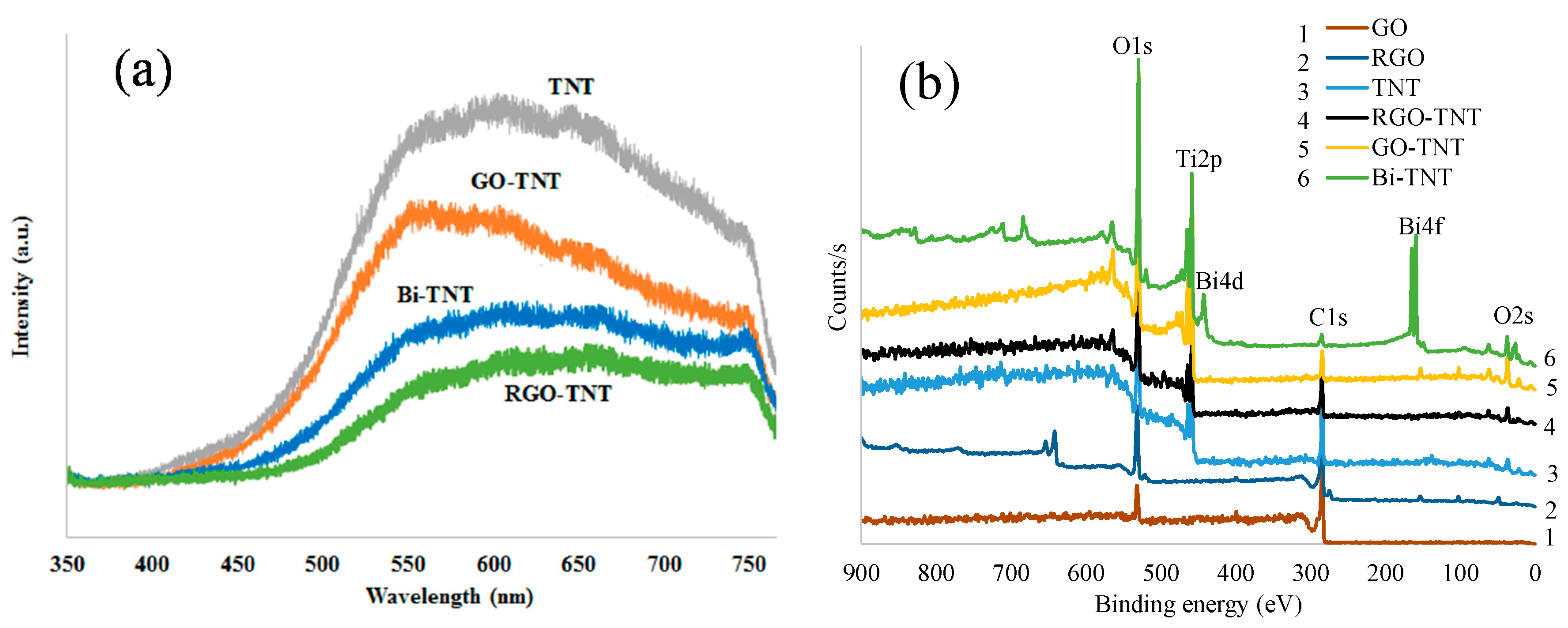
Figure 5.
Photocatalytic degradation of MB dye in a continuous-flow experiment over TNTs, UV C, and TNTs + UV C: (a) C/C0 and (b) ln(C/C0).
Figure 5.
Photocatalytic degradation of MB dye in a continuous-flow experiment over TNTs, UV C, and TNTs + UV C: (a) C/C0 and (b) ln(C/C0).

Figure 6.
Photocatalytic degradation of MB dye in a continuous-flow reactor over Vis light, TNTs + Vis light, RGO-TNTs + Vis light, Bi-TNTs + Vis light, and GO-TNTs + Vis light: (a) C/C0 and (b) ln(C/C0).
Figure 6.
Photocatalytic degradation of MB dye in a continuous-flow reactor over Vis light, TNTs + Vis light, RGO-TNTs + Vis light, Bi-TNTs + Vis light, and GO-TNTs + Vis light: (a) C/C0 and (b) ln(C/C0).

Figure 7.
Recycling of TNTs + UV C and RGO-TNTs + Vis light in a continuous-flow experiment.

Figure 8.
Schematic diagram of the one-step fabrication of modified TNTs by anodization.

Figure 9.
Image of the continuous-flow photocatalytic reactor prepared in the lab.


Table 1.
The elemental analysis of the AES spectrum of GO, RGO, TNTs and modified TNTs.
| Element (Atomic %) | Ti | O | C | Bi |
|---|---|---|---|---|
| GO | 18.6 | 81.4 | ||
| RGO | 27.2 | 72.8 | ||
| TNT | 33.4 | 62.5 | 4.1 | |
| RGO-TNT | 26.0 | 62.9 | 11.1 | |
| Bi-TNT | 12.9 | 68.9 | 8.2 | 10.0 |
| GO-TNT | 32.2 | 62.0 | 5.8 |
Table 2.
First order rate constants k and the R2 values.
| Continuous Process | Rate Constant k (h−1) | R2 |
|---|---|---|
| TNT | 0.014 | 0.759 |
| UV C | 0.050 | 0.861 |
| TNTs + UV C | 0.893 | 0.966 |
| Vis light | 0.011 | 0.809 |
| TNTs + Vis light | 0.039 | 0.953 |
| RGO-TNTs + Vis light | 0.146 | 0.977 |
| Bi-TNTs + Vis light | 0.139 | 0.981 |
| GO-TNTs + Vis light | 0.121 | 0.982 |
Table 3.
Calculation of quantum efficiency of the photocatalytic reactor using UV C and visible lamp.
Table 3.
Calculation of quantum efficiency of the photocatalytic reactor using UV C and visible lamp.
| Detail | Unit | TNTs + UV C | RGO-TNTs + Vis |
|---|---|---|---|
| Step 1: Degraded MB Molecules Calculation | |||
| MB solution | L | 2 | 2 |
| MB concentration | g L−1 | 0.005 | 0.005 |
| MB weight in solution | g | 0.01 | 0.01 |
| MB molecular weight | g mol−1 | 319.85 | 319.85 |
| No. of MB moles in a solution | mol | 3.13 × 10⁻⁵ | 3.13 × 10⁻⁵ |
| No. of MB molecules in a mole | molecules mol−1 | 6.02 × 10²³ | 6.02 × 10²³ |
| Total no. of MB molecules | molecules | 1.88 × 10¹⁹ | 1.88 × 10¹⁹ |
| MB degradation in reactor | % | 89 | 31 |
| No. of degraded MB molecules | molecules | 1.68 × 10¹⁹ | 5.84 × 10¹⁸ |
| Step 2: Photon Energy Calculation | |||
| h is Planck constant | J s | 6.63 × 10⁻³⁴ | 6.63 × 10⁻³⁴ |
| c is speed of light | m s−1 | 3.00 × 10⁸ | 3.00 × 10⁸ |
| λ is wavelength | m | 2.54 × 10⁻⁷ | 5.00 × 10⁻⁷ |
| Photon energy (hc/λ) | J | 7.83 × 10⁻¹⁹ | 3.98 × 10⁻¹⁹ |
| Lamp power | J s−1 | 16 | 8 |
| Photons/second | photon s−1 | 2.04 × 10¹⁹ | 2.01 × 10¹⁹ |
| Irradiation time | s | 9000 | 9000 |
| Total no. of photons | photon | 1.84 × 10²³ | 1.81 × 10²³ |
| Quantum efficiency | MB molecule photon−1 | 9.11 × 10⁻⁵ | 3.22 × 10⁻⁵ |
Table 4.
Description of the continuous-flow photocatalytic reactor.
| Detail | Value |
|---|---|
| Reactor length | 9 cm |
| Reactor height | 30 cm |
| Reactor width | 9 cm |
| Reactor wall thickness | 0.5 cm |
| Reactor effective volume | 1500 mL |
| Reactor material | Acrylic |
| Pipe diameter | 0.5 cm |
| Lamp diameter | 2 cm |
| Lamp length | 18 cm |
© 2018 by the authors. Licensee MDPI, Basel, Switzerland. This article is an open access article distributed under the terms and conditions of the Creative Commons Attribution (CC BY) license (http://creativecommons.org/licenses/by/4.0/).
Share and Cite
MDPI and ACS Style
Ali, I.; Kim, J.-O. Continuous-Flow Photocatalytic Degradation of Organics Using Modified TiO2 Nanocomposites. Catalysts 2018, 8, 43. https://doi.org/10.3390/catal8020043
AMA Style
Ali I, Kim J-O. Continuous-Flow Photocatalytic Degradation of Organics Using Modified TiO2 Nanocomposites. Catalysts. 2018; 8(2):43. https://doi.org/10.3390/catal8020043
Chicago/Turabian StyleAli, Imran, and Jong-Oh Kim. 2018. "Continuous-Flow Photocatalytic Degradation of Organics Using Modified TiO2 Nanocomposites" Catalysts 8, no. 2: 43. https://doi.org/10.3390/catal8020043
Note that from the first issue of 2016, this journal uses article numbers instead of page numbers. See further details here.