In-Situ Liquid Hydrogenation of m-Chloronitrobenzene over Fe-Modified Pt/Carbon Nanotubes Catalysts

1
Provincial Key Laboratory of Oil & Gas Chemical Technology, College of Chemistry & Chemical Engineering, Northeast Petroleum University, Daqing 163318, China
2
Key Laboratory of Enhanced oil & Gas Recovery of Education Ministry, College of Petroleum Engineering, Northeast Petroleum University, Daqing 163318, China
*
Author to whom correspondence should be addressed.
Catalysts 2018, 8(2), 62; https://doi.org/10.3390/catal8020062
Submission received: 11 January 2018
/
Revised: 1 February 2018
/
Accepted: 1 February 2018
/
Published: 4 February 2018
Abstract
:In-situ liquid-phase hydrogenation of m-chloronitrobenzene (m-CNB) based on aqueous-phase reforming (APR) of ethanol and catalytic hydrogenation was carried out over Fe-modified Pt/carbon nanotubes (CNTs) catalysts. The effects of Pt loading over CNTs and Fe modification on the catalytic performance of Pt/CNTs catalysts were studied. In-tube loading of Pt particles, compared with out-tube loading, considerably improved the catalytic activity. With in-tube loading, Fe-modified Pt/CNTs catalysts further improved the m-CNB in-situ hydrogenation performance. After Fe modification, Pt–Fe/CNTs catalysts formed, inside CNTs, a Pt–Fe alloy and iron oxides, which both improved catalytic hydrogenation performance and significantly enhanced ethanol APR hydrogen producing performance, thereby increasing the m-CNB in-situ hydrogenation reactivity.

1. Introduction
Aromatic haloamines are important intermediates in the chemistry of various organic compounds, such as drugs, dyes, and pesticides [1]. Compared with the traditional Bechamp reaction in a metal–acid system, catalytic hydrogenation of chloronitrobenzenes (CNBs) to chloroanilines (CANs) is of industrial interest, owing to its less severe harm to the environment. However, the selectivity of this process is not satisfactory due to the use of extensive dehalogenation and hydrogen as reducing agents, which require special equipment for H2 reservation and transportation.
In-situ hydrogenation is a new way to prepare desired chemical compounds. The aqueous-phase reforming (APR) of oxygenated hydrocarbons for hydrogen production is coupled with the organic hydrogenation in the liquid phase [2]. This novel catalytic hydrogenation system without external H2 usage has attracted much attention, owing to the simplified working process and greater safety. Xu et al. employed a Raney Ni and Ni/CMK-3 catalyst and used different hydrogen donors of methanol, ethanol, and formic acid to upgrade bio-oil model compounds and raw bio-oil through the APR of oxygenated hydrocarbons coupled with the hydrogenation of model compounds [3,4,5]. Fisk et al. upgraded bio-oil using in-situ-generated hydrogen over supported Pt catalysts [6]. Among those tested catalysts, Pt/Al2O3 exhibited the highest activity for hydrodeoxygenation of model oil, with the oxygen content decreasing from 41.4 to 2.8 wt %.
Many oxygenated compounds (e.g., methanol, ethylene glycol, glycerol, and xylitol) have been investigated in the APR process. Ethanol, derived from renewable resources such as lignocellulosic biomass, is an attractive source of H2 owing to its high hydrogen content, non-toxicity, and convenient storage and transportation. Ethanol can generate hydrogen through APR in the presence of catalysts [7,8,9]. However, selective generation of H2 and CO2 by APR is difficult because CO and/or CO2 can react with H2 to alkanes through methanation or Fischer–Tropsch reactions, which reduce hydrogen yield.
Among different transition metal catalysts, platinum catalysts have been investigated not only for APR of ethanol, but also for the hydrogenation of CNBs. However, the use of platinum is limited by its high cost and low durability due to CO-caused catalyst poisoning. It is well known that bimetallic catalysts show higher activity and stability than their monometallic analogues due to “synergistic” effects between the (two) metals [10,11]. Bimetallic Pt–Fe catalysts prepared by mixing Pt and Fe components within a single catalyst exhibit superior activity and selectivity for the APR process [12] and CNB hydrogenation [13] compared with the monometallic Pt catalyst.
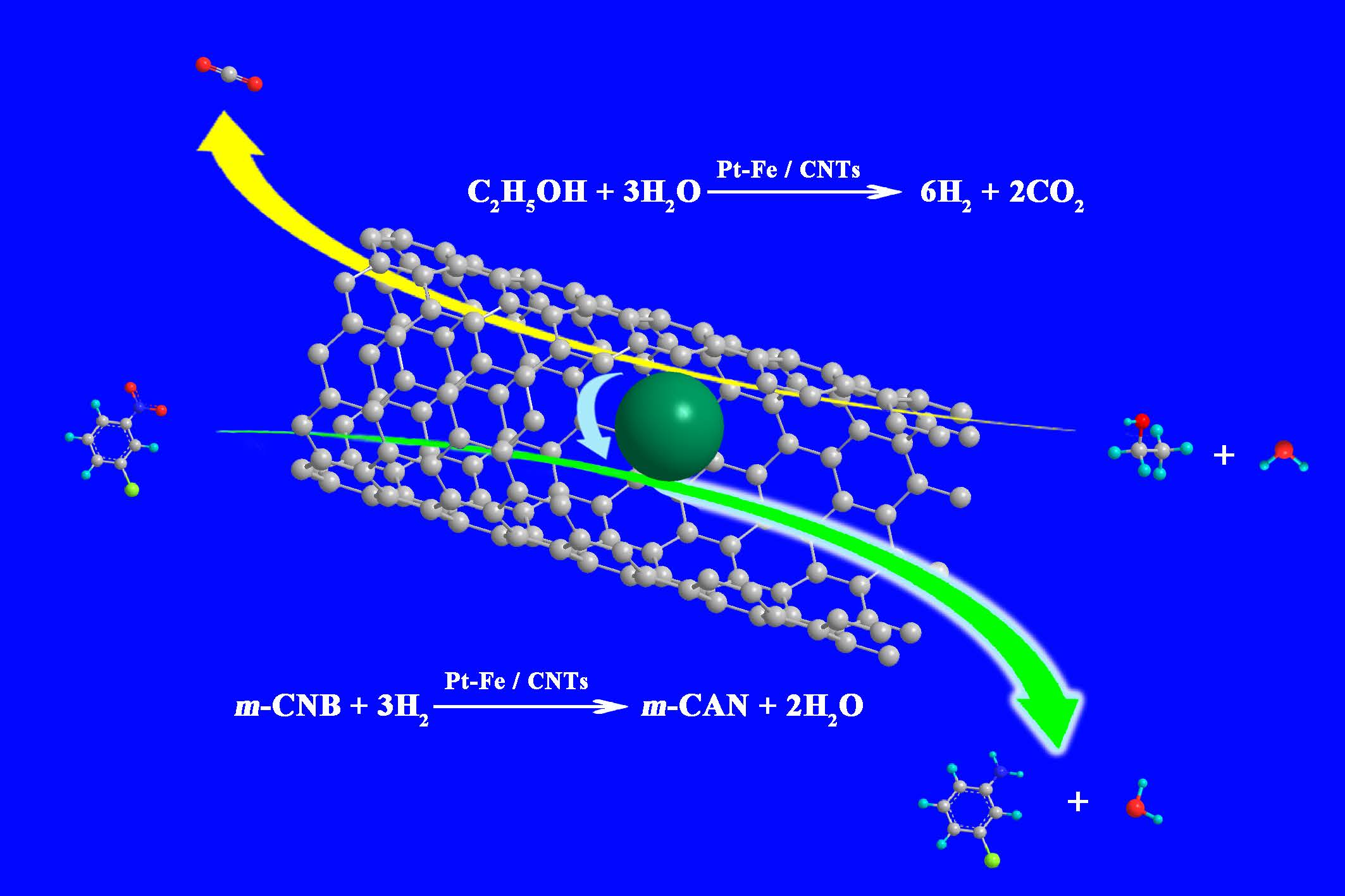
In this study, in-situ liquid-phase hydrogenation of m-CNB to m-CAN was realized over Pt/carbon nanotubes (CNTs) catalysts and Fe-modified Pt/CNTs catalysts. Specifically, ethanol was used as the hydrogen donor by APR instead of an external hydrogen source. We also studied how the Pt loading over CNTs and Fe modification would affect the catalytic performance of Pt/CNTs catalysts.
2. Results and Discussion
2.1. Catalyst Characterization
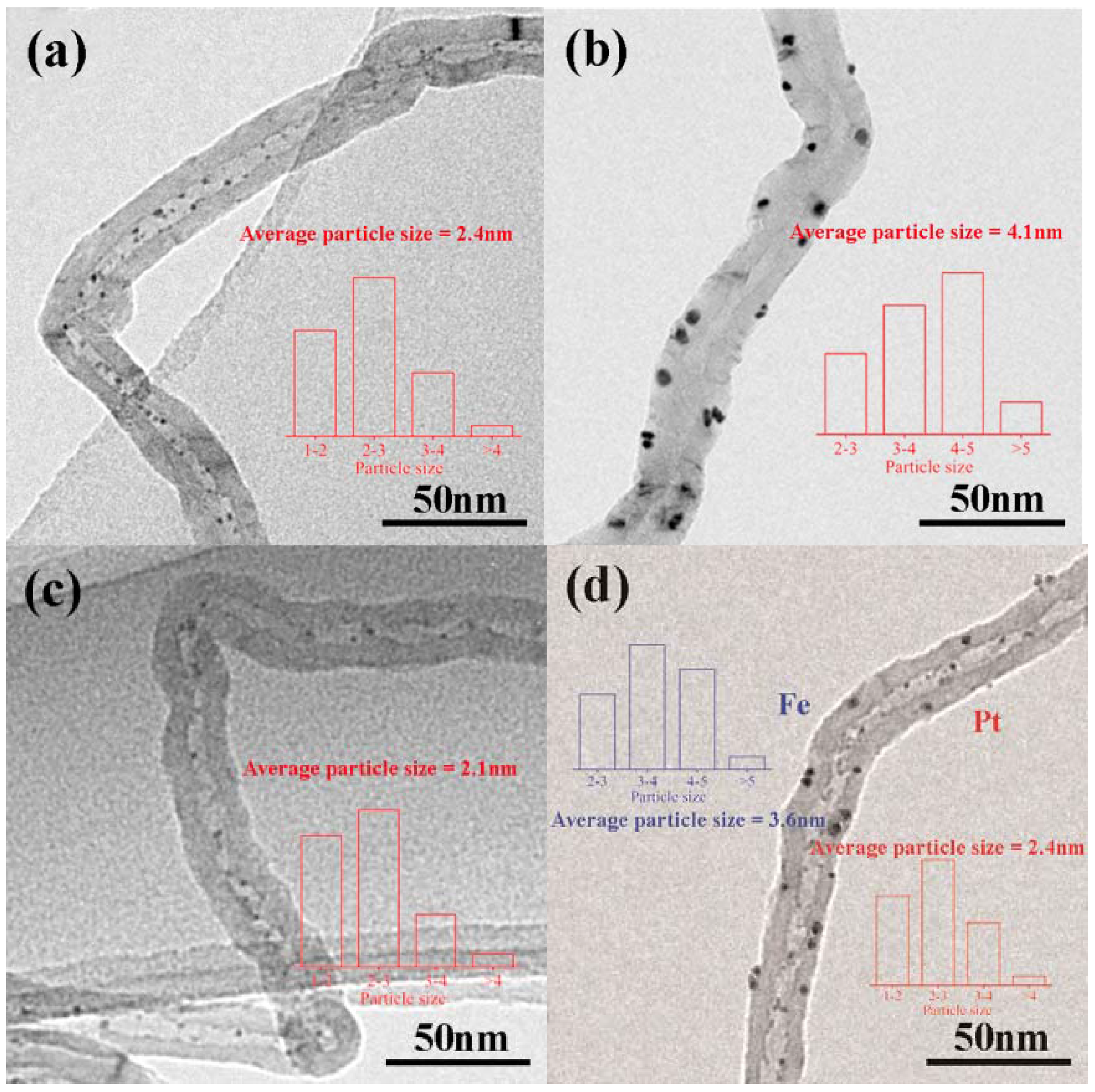
Figure 1 shows TEM images of catalysts with different loading methods, where the bars depict particle size distributions. The Pt particles in Pt–in/CNTs are homogeneously distributed inside the tubes, while the Pt particles in Pt–out/CNTs are distributed outside the tubes (Figure 1a,b). The average Pt particle sizes of Pt–in/CNTs and Pt–out/CNTs are about 2.4 and 4.1 nm, respectively. Clearly, this phenomenon can be attributed to the space confinement effect in nanotubes that restricts particle growth. For Pt–Fe(1.0)–in/CNTs, the average Pt particle size decreases to 2.1 nm compared with Pt–in/CNTs. For Pt–in–Fe–out/CNTs, the average Pt particle size inside CNTs is about 2.4 nm and the average Fe particle size outside of CNTs is about 3.6 nm.
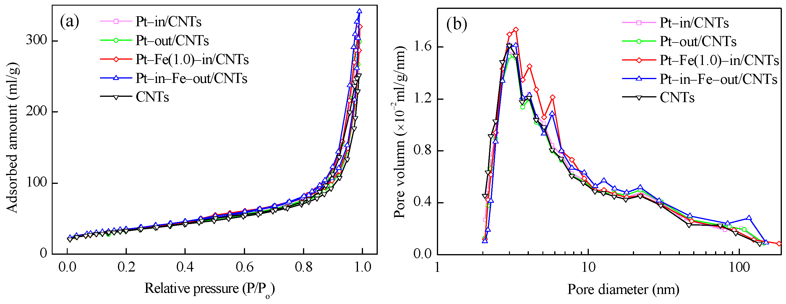
As shown in Table 1, Pt–in/CNTs and Pt–out/CNTs have similar textural characteristics, but both have smaller BET surface areas and larger pore volumes and average pore sizes compared to CNTs. It is worth noting that both in-tube and out-tube Fe modifications enlarge the BET surface area and pore volume of Pt–in/CNTs but decrease the average pore diameter. The N2 adsorption–desorption isotherms and pore size distributions of CNTs and different catalysts are shown in Figure 2. Clearly, the isotherms of CNTs and all catalysts are similar in shape and can be ascribed to Type III (Figure 2a). The introduction of Fe into CNTs increases the amount of pores with diameters from 2 to 7 nm, and the pore diameters become more uniform in Pt–Fe(1.0)–in/CNTs (Figure 2b).
The XRD patterns of catalysts with different loading modes are shown in Figure 3. All catalysts exhibit two peaks at 26.1 and 43.1°, which are ascribed to the hexagonal graphite structures (002) and (100), respectively, indicating that CNTs have a hexagonal graphite structure [14]. The XRD patterns of Pt–in/CNTs show no peak attributable to Pt, but a small hump at nearly 39.7° corresponding to Pt (111) in Pt–out/CNTs proves that the Pt particles agglomerate in Pt–out/CNTs but are highly dispersed in Pt–in/CNTs. Similarly, the characteristic peaks of Pt do not appear in Pt–Fe(1.0)–in/CNTs or Pt–in–Fe–out/CNTs with Pt confined inside the CNT channels. The absence of characteristic peaks of Fe species in Pt–Fe(1.0)–in/CNTs and Pt–in–Fe–out/CNTs can be attributed to the small load (1 wt %).
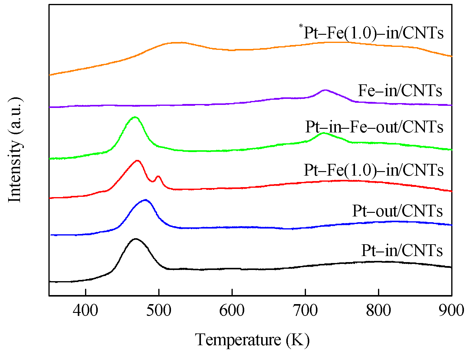
H2–TPR profiles of catalyst precursors are shown in Figure 4. It is clear that Pt–in/CNTs and Pt–out/CNTs exhibit two similar peaks, where the low-temperature peak (467 and 481 K) is ascribed to the reduction of Pt4+ that is loaded on CNTs [15], while the high-temperature peak (>600 K) can be related to the decomposition of functional groups on the surfaces of CNTs [16]. Compared with Pt–out/CNTs, the reduction peak temperature of the Pt precursor complex in the Pt–in/CNTs drops from 481 to 467 K, i.e., the Pt4+ loaded inside the CNTs is more prone to reduction than the Pt4+ loaded outside the CNTs, which can be ascribed to the confinement effect of CNTs [17,18].
Fe–in/CNTs show a reduction peak at 727 K, indicating that a high reduction temperature is required to reduce Fe oxide species to metallic Fe. Pt–Fe(1.0)–in/CNTs show two reduction peaks at 471 and 500 K, while Pt–in–Fe–out/CNTs exhibit two reduction peaks at 467 and 724 K. The Pt4+ reduction peaks of these two catalysts are not significantly different, but compared with Pt–in–Fe–out/CNTs, the reduction peak of the Fe precursor complex in Pt–Fe(1.0)–in/CNTs drops from 724 to 500 K. Under the influence of the hydrogen overflow effect [19], the presence of platinum favors the iron reduction, and hydrogen is likely to be dissociatively adsorbed onto Pt0 particles, thus decreasing the reduction temperature of nearby iron cations. The reduced Pt–Fe(1.0)–in/CNTs was oxidized again for H2–TPR trials (*Pt–Fe(1.0)–in/CNTs) and showed one reducing peak at 525 K on the H2–TPR spectrum. This temperature was between the Pt reducing peak temperature in Pt–in/CNTs and the Fe reducing peak temperature in Fe–in/CNTs, indicating that Pt and Fe formed a Pt–Fe alloy during hydrogen reduction.
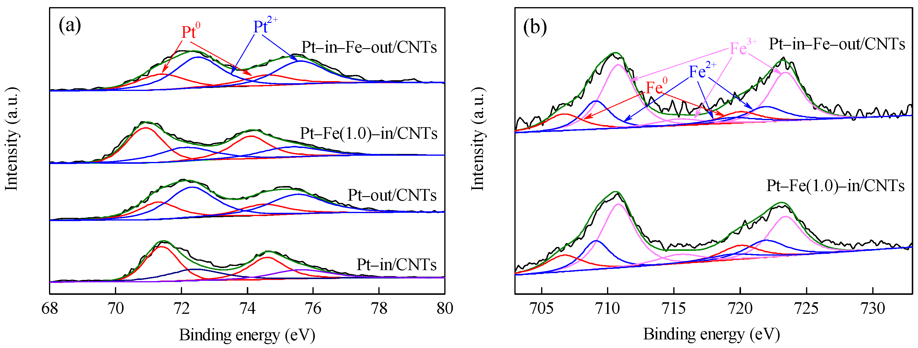
Pt 4f and Fe 2p XPS spectra of CNTs-supported catalysts are shown in Figure 5, and the element compositions with different chemical states calculated from the peak areas are listed in Table 1. As shown in Figure 5, the Pt species in all catalysts exist as metallic Pt0 and oxidized Pt2+, while the Fe species are present as metallic Fe0 and oxidized Fe2+ and Fe3+ (FexOy, including FeO, Fe2O3 and Fe3O4) [20,21,22]. Yan et al. modified the Ru/Al2O3 catalyst with iron salt as a precursor and found the iron salt after hydrogen reduction at 573 K mainly existed as Fe3O4 [23]. Comparison between Pt–in/CNTs and Pt–out/CNTs shows that the binding energies (BEs) of Pt with different chemical states are not different between the two catalysts. However, the percentage of Pt0/(Pt0+Pt2+) in Pt–in/CNTs is much higher than that of Pt–out/CNTs (52.8% vs. 31.5%), indicating that the reduction of Pt4+ to Pt0 significantly occurs more easily inside CNTs than outside CNTs. Chen et al. found the confinement of Fe particles within CNTs improved reducibility and hence promoted the formation of catalytically active iron carbide species under reaction conditions [24]. Compared with Pt–in/CNTs, the Pt 4f7/2 BE decreases from 71.4 to 70.9 eV in Pt–Fe(1.0)–in/CNTs, but does not change in Pt–in–Fe–out/CNTs and is still 71.4 eV. This is because the Pt and Fe in Pt–in–Fe–out/CNTs are located inside and outside of CNTs, respectively, rather than being under contact or experiencing electron transfer. On the contrary, the Pt and Fe in Pt–Fe(1.0)–in/CNTs are both loaded inside CNTs and interact chemically with each other. The Fe0 BE of Pt–Fe(1.0)–in/CNTs at 706.8 eV is higher than the standard value of 706.7 eV, which further confirms electron donation from Fe to Pt to form electron-rich Pt. These results indicate that, in addition to the form of FexOy, a part of Fe bonded with Pt to form a Pt–Fe alloy [23]. Moreover, after Fe modification, the particle sizes inside CNTs decline from 2.4 nm in the Pt–in/CNTs to 2.1 nm in the Pt–Fe(1.0)–in/CNTs (Figure 1), while the size-dependent effect of the nanoparticles could also result in the BE decrease of Pt [25].
2.2. Catalytic Activity of Catalysts
Table 2 presents the in-situ hydrogenation of m-CNB over CNTs, Pt–in/CNTs, and Pt–out/CNTs. The blank experiments show that CNTs do not exhibit the in-situ hydrogenation activity of m-CNB. The m-CNB in-situ hydrogenation activities of Pt–in/CNTs and Pt–out/CNTs are 18.6 and 12.3 h−1, respectively, with the corresponding m-CAN selectivity of 94.6% and 96.3%, respectively. These results indicate that the different loading methods of Pt particles to CNTs significantly affected the catalytic activity. CNTs can be considered as a one-dimensional tubular material curled by graphene sheets, since the π electron clouds, which were originally symmetrically distributed due to the curvature, were distorted to move from inside to outside of the tubes. Such intratubal nano-space and electron structure endowed CNTs with a unique catalysis confinement effect during catalyst preparation and catalysis applications. During catalyst preparation, compared with out-tube loading, the in-tube loading was impacted by the intratubal nano-space and electron structure of CNTs, which limited the aggregation and growth of metal particles and promoted the reduction of metal ions [24], which is in agreement with the result of TEM (Figure 1), H2–TPR (Figure 4), and XPS (Table 1), thereby enlarging the active specific surface areas of catalysts. From the perspective of catalysis, the CNTs interacted with the reactant molecules, leading to local concentration enrichment, thereby promoting catalysis.
Table 3 presents the in-situ hydrogenation of m-CNB over Fe-modified Pt–in/CNTs. An appropriate addition of Fe could significantly enhance the m-CNB in-situ hydrogenation activity of the Pt–in/CNTs. Compared with the Pt–in/CNTs, the m-CNB in-situ hydrogenation activity of 1 wt % Fe-modified Pt–in/CNTs was enhanced from 10.0 to 76.7 h−1. With a further increase in Fe load, the m-CNB in-situ hydrogenation activity of Pt–Fe(x)–in/CNTs (x > 1.0) was reduced. This was because the high Fe load increased FexOy concentration and accelerated the water–gas shift (WGS) and the Fischer–Tropsch synthesis (FTS), thereby slowing down the CO adsorption poisoning and allowing more Pt–Fe active centers to participate in in-situ liquid-phase hydrogenation. However, excessive load of FexOy led to the overconsumption of ethanol water during FTS, leading to reformed active hydrogen. Meanwhile, a part of Pt–Fe active sites were covered by FexOy, which reduced the effective utilization rate of active components [26]. On the contrary, the Fe–in/CNTs did not show the m-CNB in-situ hydrogenation activity, while the catalytic activity of Pt–in–Fe–out/CNTs was improved only to 16.7 h−1. Given that Pt and Fe were loaded inside and outside of the CNTs, respectively, in the Pt–in–Fe–out/CNTs, and were nearly used alone, it can be stated that Fe had no catalytic activity.
H2–TPR (Figure 4) and XPS (Figure 5) show that the metals of Pt–Fe–in/CNTs exist as Pt–Fe alloy and FexOy. The m-CNB in-situ hydrogenation of Pt–Fe–in/CNTs mainly involved two reactions: m-CNB catalytic hydrogenation and ethanol APR hydrogen generation. Clearly, with the presence of H2, the noble metal Pt could undergo m-CNB catalytic hydrogenation at normal temperature and normal pressure, while the Fe modification further enhanced the catalytic activity [27,28]. Zhao et al. studied the hydrogenation of p-CNB on an Fe-modified NiCoB nanoalloy catalyst and believed that the oxidized state of the Fe modifier had a unique Lewis acidity, which influenced the product distributions in the p-CNB hydrogenation [20]. Therefore, compared with hydrogenation of m-CNB using molecular hydrogen, APR of ethanol for hydrogen generation is important for m-CNB in-situ hydrogenation.
Ethanol is the simplest molecule containing a single-bonded C–C–O backbone. The ethanol rupture mainly involved the C–C bond rupture, which forms H2 and C–O bond rupture which mainly forms different alkane compounds. The generation of H2 and CO2 by ethanol APR is an ideal situation. Pt-based catalysts are a type of noble metal catalysts that can be used in ethanol reforming-based hydrogen preparation [29,30,31,32]. During the hydrogen generation via ethanol reforming on Pt-based catalysts, the O–H and C–H of ethanol needed similar energy, but Pt–C was more stable than Pt–O and more likely to be formed [33,34]. Thus, ethanol molecules tended to undergo C–C bond rupture on Pt active sites, forming CO and H2, while CO further reacted with water to form CO2 and H2. However, in practice, this reaction is a complex process with much more diverse product distribution. On one hand, APR of ethanol is performed at low temperature and high pressure to maintain liquid-phase conditions. The low temperature highly favors the FTS reactions of H2 and CO or CO2 to form alkanes. The non-activated methyl group is easily transformed to CH4 [7]. Alkanes can also form by parallel pathways involving cleavage of C–O bonds. On the other hand, the adsorbed CO leads to low catalytic activity. Therefore, the adsorbed CO must be removed from the catalyst surface by WGS reaction to form CO2 and H2 [35,36]. Thus, a good APR of ethanol process must inhibit C–O bond cleavage, FTS, and methanation reactions, but are rapid at C–C bond cleavage and WGS reaction.
Different from Pt–in/CNTs single-metal loaded catalysts, the Pt–Fe(1.0)–in/CNTs were found to form a Pt–Fe alloy and FexOy. Kim et al. studied the APR of polyols for hydrogen production using mesoporous carbon-supported Pt–Fe bimetallic catalysts and found that Fe-modified Pt/CMK-9 can activate C–C bond cleavage, contribute to the promoting ability of the WGS reactions, and prevent methanation and FTS reactions [12]. Huber et al. studied the APR of ethylene glycol over Pd/Al2O3 catalysts and found that the APR activity can be increased by adding Fe2O3 that acted as a WGS promoter [37]. In addition, the formation of Fe3O4 via Fe2O3 reduction can increase the number of Lewis acid sites [38]. The stronger Pt-metal oxide nanoparticle interaction with weaker surface acidity enhanced the H2 productivity and inhibited coke formation [39]. As reported, Fe3O4 is an excellent catalyst for WGS and FTS reactions and can enhance the CO poisoning resistance of the catalyst [40,41,42]. Thus, the existence of the Pt–Fe alloy and FexOy in Pt–Fe(1.0)–in/CNTs can improve the APR of ethanol reactivity and H2 selectivity, thereby increasing the m-CNB in-situ hydrogenation activity.
2.3. In-Situ Hydrogenation of m-CNB
Table 4 shows the in-situ hydrogenation of m-CNB over Pt–Fe(1.0)–in/CNTs under different reaction conditions. The water and ethanol in the reaction system act as solvents and hydrogen suppliers. With the increase in the water/ethanol ratio, the m-CNB catalytic hydrogenation reactivity first increased and then declined, maximizing at a water/ethanol ratio of 3:7. This was because, with a low water content, the surface acid sites on the catalyst were prone to catalytic ethanol dehydrogenation/dehydration, forming by-products such as aldehyde and ethylene and reducing H2 selectivity [2,20,43]. Moreover, the high ethanol concentrations enhanced its competitive adsorption for active sites over m-CNB and thereby inhibited hydrogenation [37]. The increase in water content can promote H2 production and reduce CO with APR and WGS reactions [44]. However, with further water addition, the water insolubility of m-CNB would reduce the solubility in the water–ethanol system. The rise of reaction temperature only slightly affected the m-CAN selectivity, but increased the m-CNB in-situ hydrogenation activity. As the reaction temperature rose from 433 to 453 K, the catalytic activity was enhanced from 57.6 to 74.1 h−1, and with a further temperature rise to 473 K, the catalytic activity increased slowly to 76.7 h−1. This was because a high reaction temperature can accelerate the endothermic ethanol APR hydrogen generation and quicken the vapor transformation to remove surface CO [45,46], but excessively high temperature was unfavorable for exothermic nitro-hydrogenation [47]. The N2 pressure did not largely affect the m-CNB catalytic activity or m-CAN selectivity. The m-CNB in-situ hydrogenation mainly depends on the active hydrogen atoms generated from APR, which is not affected by pressure [48,49].
3. Materials and Methods
3.1. Chemicals
CNTs were obtained from Shenzhen Nanotech Port Co., Ltd. (Shenzhen, China, with purity of >97.0%). H2PtCl6 was purchased from Shenyang Jinke Reagent Company (Shenyang, China). Fe(NO3)3·6H2O was purchased from Beijing Shuanghuan Chemical Reagents Company (Beijing, China). HNO3 and C2H5OH were obtained from Haerbin Chemical Reagent Company (Haerbin, China). All the chemicals were of analytical grade and used with no further treatment. Deionized water was used for solution preparation.
3.2. Catalyst Preparation
Pt/CNTs with Pt particles loaded inside or outside of CNTs, marked as Pt–in/CNTs and Pt–out/CNTs, respectively, were prepared based on the difference between ethanol–CNT interface energy and water-CNT interface energy [50]. Prior to impregnation, the raw CNTs were refluxed in 68 wt % HNO3 for 6 h. For Pt–in/CNTs, 0.1 g CNTs were impregnated first with 0.35 mL of H2PtCl6 ethanol solution and then with 0.26 mL of H2O. After drying, the precursor was reduced in an H2 flow at 573 K for 3 h. The Pt theoretical load was 2 wt %. For Pt–out/CNTs, 0.1 g CNTs were impregnated first with 0.52 mL of ethanol and then with 0.35 mL of H2PtCl6 aqueous solution. After these were dried and reduced, Pt–out/CNTs were prepared. Fe-modified Pt–in/CNT catalysts with different Fe loads were prepared using a mixed ethanol solution of H2PtCl6 and Fe(NO3)3, while the other steps were the same as those of Pt–in/CNTs. The catalysts were denoted as Pt–Fe(x)–in/CNTs, where x is the Fe load (wt %). For comparison, the catalyst with 2 wt % Pt loaded inside the CNTs and 1 wt % Fe loaded outside the CNTs was prepared and denoted as Pt–in–Fe–out/CNTs. The catalyst with 1 wt % Fe loaded inside the CNTs was denoted as Fe–in/CNTs.
3.3. Catalyst Characterization
The catalyst morphologies were observed with a transmission electron microscope (TEM, JEOL JEM-4000EX, Tikyo, Japan). X-ray diffraction (XRD) analysis was performed on a Rigaku D/max-2200 XRD meter using Cu Kα radiation (Rigaku, Tokyo, Japan). The textural properties of the catalysts were determined by the Brunauer–Emmett–Teller (BET) method using a Tristar II 3020 surface area and porosity analyzer (Micromeritic, Atlanta, GA, USA). X-ray photoelectron spectrometer (XPS) spectra were acquired with a Thermo Fisher Scientific K-Alpha instrument (Thermofisher, New York, NY, USA). Temperature programmed reduction (TPR) was performed on a Chem BET 3000 chemical adsorption instrument (Quantachrome, Boynton Beach, FL, USA). Samples were heated at 10 K/min from room temperature to 1173 K in a 5 vol % H2/N2 mixture flow (30 mL/min).
3.4. Catalytic Test
In-situ hydrogenation of m-CNB was carried out in a mechanically stirred 50 mL stainless autoclave. Certain amounts of m-CNB, ethanol, deionized water, and a catalyst were loaded into a reactor, which was purged with N2 in advance to remove air. After that, the mixture was heated to the reaction temperature and mixed at 600 rpm to eliminate the effect of diffusion on dynamics. After the reaction, the reactor was cooled down to ambient temperature, and the liquid products were then analyzed with gas chromatography (GC, Shimadzu GC-14C, FID, SE-30 capillary column, Tokyo, Japan) and identified by gas chromatography/mass spectrometry (GC/MS, Agilent 5890, Santa Clara, CA, USA).
4. Conclusions
Pt/CNTs were prepared with Pt particles loaded inside or outside of CNTs. Pt/CNTs were used into ethanol APR for hydrogen generation, and the resulting H2 was directly used in m-CNB hydrogenation, which realized the in-situ hydrogenation without extra hydrogen addition condition. Compared with out-tube loading, the Pt/CNTs prepared from in-tube loading was affected by the confinement effect of CNTs and showed very high m-CNB in-situ hydrogenation activity. Pt–Fe/CNTs were prepared from Fe modification and Pt–Fe in-tube loading into CNTs. The formation of Pt–Fe alloy and the existence of FexOy improved the m-CNB hydrogenation activity and significantly enhanced the ethanol APR hydrogenation activity, which together increased the H2 selectivity and thereby the m-CNB in-situ hydrogenation activity.
Acknowledgments
The authors acknowledge the financial support from the Graduate Innovation Project of Northeast Petroleum University (YJSCX2016-020NEPU).
Author Contributions
Feng Li and Hua Song conceived and designed the experiments; Feng Li, Jinrong Liang, and Wenxi Zhu performed the experiments; Hua Song, Keliang Wang, and Cuiqin Li analyzed the data; Feng Li contributed reagents/materials/analysis tools; Feng Li and Hua Song wrote the paper.
Conflicts of Interest
The authors declare no conflict of interest.
References
- Xiong, J.; Chen, J.; Zhang, J. Liquid-phase hydrogenation of O-chloronitrobenzene over supported nickel catalysts. Catal. Commun. 2007, 8, 345–350. [Google Scholar] [CrossRef]
- Cortright, R.D.; Davda, R.; Dumesic, J.A. Hydrogen from catalytic reforming of biomass-derived hydrocarbons in liquid water. Nature 2002, 418, 964–967. [Google Scholar] [CrossRef] [PubMed]
- Xu, Y.; Long, J.; Liu, Q.; Li, Y.; Wang, C.; Zhang, Q.; Lv, W.; Zhang, X.; Qiu, S.; Wang, T.; et al. In situ hydrogenation of model compounds and raw bio-oil over Raney Ni catalyst. Energy Convers. Manag. 2015, 89, 188–196. [Google Scholar] [CrossRef]
- Xu, Y.; Li, Y.; Wang, C.; Wang, C.; Ma, L.; Wang, T.; Zhang, X.; Zhang, Q. In-situ hydrogenation of model compounds and raw bio-oil over Ni/CMK-3 catalyst. Fuel Process. Technol. 2017, 161, 226–231. [Google Scholar] [CrossRef]
- Xu, Y.; Qiu, S.; Long, J.; Wang, C.; Chang, J.; Tan, J.; Liu, Q.; Ma, L.; Wang, T.; Zhang, Q. In situ hydrogenation of furfural with additives over a RANEY®Ni catalyst. RSC. Adv. 2015, 5, 91190–91195. [Google Scholar] [CrossRef]
- Fisk, C.A.; Morgan, T.; Ji, Y.; Crocker, M.; Crofcheck, C.; Lewis, S.A. Bio-oil upgrading over platinum catalysts using in situ generated hydrogen. Appl. Catal. A 2009, 358, 150–156. [Google Scholar] [CrossRef]
- Nozawa, T.; Mizukoshi, Y.; Yoshida, A.; Naito, S. Aqueous phase reforming of ethanol and acetic acid over TiO2 supported Ru catalysts. Appl. Catal. B 2014, 146, 221–226. [Google Scholar] [CrossRef]
- Nozawa, T.; Yoshida, A.; Hikichi, S.; Naito, S. Effects of Re addition upon aqueous phase reforming of ethanol over TiO2 supported Rh and Ir catalysts. Int. J. Hydrogen Energy 2015, 40, 4129–4140. [Google Scholar] [CrossRef]
- Xiong, H.; DeLaRiva, A.; Wang, Y.; Datye, A.K. Low-temperature aqueous-phase reforming of ethanol on bimetallic PdZn catalysts. Catal. Sci. Technol. 2014, 5, 254–263. [Google Scholar] [CrossRef]
- Sankar, M.; Dimitratos, N.; Miedziak, P.J.; Wells, P.P.; Kiely, C.J.; Hutchings, G.J. Designing bimetallic catalysts for a green and sustainable future. Chem. Soc. Rev. 2012, 41, 8099–8139. [Google Scholar] [CrossRef] [PubMed]
- Santo, V.D.; Gallo, A.; Naldoni, A.; Guidotti, M.; Psaro, R. Bimetallic heterogeneous catalysts for hydrogen production. Catal. Today 2012, 197, 190–205. [Google Scholar] [CrossRef]
- Kim, M.C.; Kim, T.W.; Kim, H.J.; Kim, C.U.; Bae, J.W. Aqueous phase reforming of polyols for hydrogen production using supported PtFe bimetallic catalysts. Renew. Energy 2016, 95, 396–403. [Google Scholar] [CrossRef]
- Han, X.; Zhou, R.; Lai, G.; Yue, B.; Zheng, X. Effect of transition metal (Cr, Mn, Fe, Co, Ni and Cu) on the hydrogenation properties of chloronitrobenzene over Pt/TiO2 catalysts. J. Mol. Catal. A 2004, 209, 83–87. [Google Scholar] [CrossRef]
- Cano, O.A.; González, C.A.R.; Paz, J.F.H.; Madrid, P.A.; Casillas, P.E.G.; Hernández, A.C.M.; Pérez, C.A.M. Catalytic activity of palladium nanocubes/multiwalled carbon nanotubes structures for methyl dye removal. Catal. Today 2017, 282, 168–173. [Google Scholar] [CrossRef]
- Yang, L.; Lin, G.D.; Zhang, H.B. Highly efficient Pd-ZnO catalyst doubly promoted by CNTs and Sc2O3 for methanol steam reforming. Appl. Catal. A 2013, 455, 137–144. [Google Scholar] [CrossRef]
- Stassi, J.P.; Zgolicz, P.D.; de Miguel, S.R.; Scelza, O.A. Formation of different promoted metallic phases in PtFe and PtSn catalysts supported on carbonaceous materials used for selective hydrogenation. J. Catal. 2013, 306, 11–29. [Google Scholar] [CrossRef]
- Deng, D.; Yu, L.; Chen, X.; Wang, G.; Jin, L.; Pan, X.; Deng, J.; Sun, G.; Bao, X. Iron encapsulated within pod-like carbon nanotubes for oxygen reduction reaction. Angew. Chem. Int. Ed. 2013, 52, 371–375. [Google Scholar] [CrossRef] [PubMed]
- Zhang, Y.; Liu, Y.; Yang, G.; Endo, Y.; Tsubaki, N. The solvent effects during preparation of Fischer-Tropsch synthesis catalysts: Improvement of reducibility, dispersion of supported cobalt and stability of catalyst. Catal. Today 2009, 142, 85–89. [Google Scholar] [CrossRef]
- Sirijaruphan, A.; Goodwin, J.G.; Rice, R.W. Effect of Fe promotion on the surface reaction parameters of Pt/γ-Al2O3 for the selective oxidation of CO. J. Catal. 2004, 224, 304–313. [Google Scholar] [CrossRef]
- Zhao, B.; Chen, Y.W. Hydrogenation of p-chloronitrobenzene on Mo, La, Fe, and W-modified NiCoB nanoalloy catalysts. J. Noncryst. Solids 2010, 356, 839–847. [Google Scholar] [CrossRef]
- Grosvenor, A.P.; Kobe, B.A.; Biesinger, M.C.; McIntyre, N.S. Investigation of multiplet splitting of Fe 2p XPS spectra and bonding in iron compounds. Surf. Interface Anal. 2004, 36, 1564–1574. [Google Scholar] [CrossRef]
- Yamashita, T.; Hayes, P. Analysis of XPS spectra of Fe2+ and Fe3+ ions in oxide materials. Appl. Surf. Sci. 2008, 254, 2441–2449. [Google Scholar] [CrossRef]
- Chen, A.A.; Xu, X.S.; Hua, Y.X.; Gu, H.Z.; Yan, X.H. Fe3O4 modified alumina supported ruthenium catalyst for novel in-situ liquid phase catalytic hydrogenation. Acta Phys. Chim. Sin. 2013, 29, 799–805. [Google Scholar]
- Chen, W.; Fan, Z.; Pan, X.; Bao, X. Effect of confinement in carbon nanotubes on the activity of Fischer-Tropsch iron catalyst. J. Am. Chem. Soc. 2008, 130, 9414–9419. [Google Scholar] [CrossRef] [PubMed]
- Antonetti, C.; Oubenali, M.; Galletti, A.M.R.; Serp, P.; Vannucci, G. Novel microwave synthesis of ruthenium nanoparticles supported on carbon nanotubes active in the selective hydrogenation of p-chloronitrobenzene to p-chloroaniline. Appl. Catal. A 2012, 421, 99–107. [Google Scholar] [CrossRef]
- Yan, X.; Sun, J.; Wang, Y.; Yang, J. A Fe-promoted Ni-P amorphous alloy catalyst (Ni-Fe-P) for liquid phase hydrogenation of m- and p-chloronitrobenzene. J. Mol. Catal. A 2006, 252, 17–22. [Google Scholar] [CrossRef]
- Xu, X.; Li, X.; Gu, H.; Huang, Z.; Yan, X. A highly active and chemoselective assembled Pt/C(Fe) catalyst for hydrogenation of o-chloronitrobenzene. Appl. Catal. A 2012, 429, 17–23. [Google Scholar] [CrossRef]
- Zhang, J.; Wang, Y.; Ji, H.; Wei, Y.; Wu, N.; Zuo, B.; Wang, Q. Magnetic nanocomposite catalysts with high activity and selectivity for selective hydrogenation of ortho-chloronitrobenzene. J. Catal. 2005, 229, 114–118. [Google Scholar] [CrossRef]
- Bossola, F.; Pereira-Hernández, X.I.; Evangelisti, C.; Wang, Y.; Santo, V.D. Investigation of the promoting effect of Mn on a Pt/C catalyst for the steam and aqueous phase reforming of glycerol. J. Catal. 2017, 349, 75–83. [Google Scholar] [CrossRef]
- Kourtelesis, M.; Panagiotopoulou, P.; Verykios, X. Influence of structural parameters on the reaction of low temperature ethanol steam reforming over Pt/Al2O3 catalsyts. Catal. Today 2015, 258, 247–255. [Google Scholar] [CrossRef]
- Bilal, M.; Jackson, S.D. Ethanol steam reforming over Pt/Al2O3 catalysts: The effect of impurities on selectivity and catalyst deactivation. Appl. Catal. A 2017, 529, 98–107. [Google Scholar] [CrossRef]
- He, C.; Zheng, J.; Wang, K.; Lin, H.; Wang, J.Y.; Yang, Y. Sorption enhanced aqueous phase reforming of glycerol for hydrogen production over Pt–Ni supported on multi-walled carbon nanotubes. Appl. Catal. B 2015, 162, 401–411. [Google Scholar] [CrossRef]
- Greeley, J.; Mavrikakis, M. A first-principles study of methanol decomposition on Pt(111). J. Am. Chem. Soc. 2002, 124, 7193–7201. [Google Scholar] [CrossRef] [PubMed]
- Yang, J.; Sun, J.; Li, X.; Yan, X. Liquid-phase hydrogenation of nitrobenzene to aniline using solvent hydrogen from ethanol reforming. Chin. J. Catal. 2006, 27, 559–561. [Google Scholar]
- Larimi, A.S.; Kazemeini, M.; Khorasheh, F. Aqueous phase reforming of glycerol using highly active and stable Pt0.05CexZr0.95–xO2 ternary solid solution catalysts. Appl. Catal. A 2016, 523, 230–240. [Google Scholar] [CrossRef]
- Ciftci, A.; Michel Ligthart, D.A.J.; Oben Sen, A.; van Hoof, A.J.F.; Friedrich, H.; Hensen, E.J.M. Pt-Re synergy in aqueous-phase reforming of glycerol and the water-gas shift reaction. J. Catal. 2014, 311, 88–101. [Google Scholar] [CrossRef]
- Yu, Y.; Xu, Y.; Wang, T.; Ma, L.; Zhang, Q.; Zhang, X.; Zhang, X. In-situ hydrogenation of lignin depolymerization model compounds to cyclohexanol. J. Fuel Chem. Technol. 2013, 41, 443–448. [Google Scholar] [CrossRef]
- Soares, A.V.H.; Atia, H.; Armbruster, U.; Passos, F.B.; Martin, A. Platinum, palladium and nickel supported on Fe3O4 as catalysts for glycerol aqueous-phase hydrogenolysis and reforming. Appl. Catal. A 2017, 548, 179–190. [Google Scholar] [CrossRef]
- He, Z.; Yang, M.; Wang, X.; Zhao, Z.; Duan, A. Effect of the transition metal oxide supports on hydrogen production from bio-ethanol reforming. Catal. Today 2012, 194, 2–8. [Google Scholar] [CrossRef]
- Li, T.; Yang, Y.; Tao, Z.; Zhang, C.; Xiang, H.; Li, Y. Study on an iron-manganese Fischer-Tropschsynthesis catalyst prepared from ferrous sulfate. Fuel Process. Technol. 2009, 90, 1247–1251. [Google Scholar] [CrossRef]
- Wan, H.J.; Wu, B.S.; Li, T.Z.; Tao, Z.C.; Xia, A.; Xiang, H.W.; Li, Y.W. Study of an iron-based Fischer-Tropsch synthesis catalyst incorporated with SiO2. J. Fuel Chem. Technol. 2007, 35, 589–594. [Google Scholar] [CrossRef]
- Smit, E.D.; Beale, A.M.; Nikitenko, S.; Weckhuysen, B.M. Local and long range order in promoted iron-based Fischer-Tropsch catalysts: A combined in situ X-ray absorption spectroscopy/wide angle X-ray scattering study. J. Catal. 2009, 262, 244–256. [Google Scholar] [CrossRef]
- Deluga, G.; Salge, J.R.; Schmidt, L.D.; Verykios, X.E. Renewable hydrogen from ethanol by autothermal reforming. Science 2004, 303, 993–997. [Google Scholar] [CrossRef] [PubMed]
- Zhou, L.; Gu, H.; Yan, X. A novel transfer hydrogenation with high hydrogen utilization for the hydrogenation of halogenated nitrobenzene without hydrodehalogenation. Catal. Lett. 2009, 132, 16–21. [Google Scholar] [CrossRef]
- Li, X.; Xiang, Y. A novel liquid system of catalytic hydrogenation. Sci. China Ser. B 2007, 50, 746–753. [Google Scholar] [CrossRef]
- Liu, L.; Qiao, B.; Chen, Z.; Zhang, J.; Deng, Y. Novel chemoselective hydrogenation of aromatic nitro compounds over ferric hydroxide supported nanocluster gold in the presence of CO and H2O. Chem. Commun. 2009, 6, 653–655. [Google Scholar] [CrossRef] [PubMed]
- Fatsikostas, A.N.; Kondarides, D.I.; Verykios, X.E. Production of hydrogen for fuel cells by reformation of biomass-derived ethanol. Catal. Today 2002, 75, 145–155. [Google Scholar] [CrossRef]
- Yin, A.Y.; Guo, X.Y.; Dai, W.L.; Fan, K.N. The synthesis of propylene glycol and ethylene glycol from glycerol using Raney Ni as a versatile catalyst. Green Chem. 2009, 11, 1514–1516. [Google Scholar] [CrossRef]
- Kong, D.; Jiang, T.; Zhang, Y.; Cao, F. Catalytic performance of activated carbon supported Pt–Ni biometallic catalyst for glycerol in situ hydrogenolysis. Chem. J. Chin. Univ. 2016, 36, 1140–1147. [Google Scholar]
- Tessonnier, J.P.; Ersen, O.; Weinberg, G.; Pham-Huu, C.; Su, D.S.; Schlögl, R. Selective deposition of metal nanoparticles inside or outside multiwalled carbon nanotubes. ACS Nano 2009, 3, 2081–2089. [Google Scholar] [CrossRef] [PubMed]
Figure 1.
TEM images of (a) Pt–in/CNTs, (b) Pt–out/CNTs, (c) Pt–Fe(1.0)–in/CNTs, and (d) Pt–in–Fe–out/CNTs.
Figure 1.
TEM images of (a) Pt–in/CNTs, (b) Pt–out/CNTs, (c) Pt–Fe(1.0)–in/CNTs, and (d) Pt–in–Fe–out/CNTs.

Figure 2.
(a) N2 adsorption–desorption isotherms and (b) pore size distribution curves of CNTs, Pt–in/CNTs, Pt–out/CNTs, Pt–Fe(1.0)–in/CNTs, and Pt–in–Fe–out/CNTs.
Figure 2.
(a) N2 adsorption–desorption isotherms and (b) pore size distribution curves of CNTs, Pt–in/CNTs, Pt–out/CNTs, Pt–Fe(1.0)–in/CNTs, and Pt–in–Fe–out/CNTs.

Figure 3.
XRD patterns of Pt–in/CNTs, Pt–out/CNTs, Pt–Fe(1.0)–in/CNTs, and Pt–in–Fe–out/CNTs. (a) 2θ = 10–80°, (b) 2θ = 30–50°.
Figure 3.
XRD patterns of Pt–in/CNTs, Pt–out/CNTs, Pt–Fe(1.0)–in/CNTs, and Pt–in–Fe–out/CNTs. (a) 2θ = 10–80°, (b) 2θ = 30–50°.
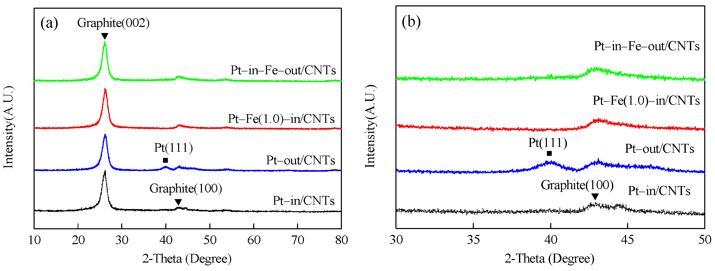
Figure 4.
H2–TPR profiles of Pt–in/CNTs, Pt–out/CNTs, Pt–Fe(1.0)–in/CNTs, Pt–in–Fe–out/CNTs, Fe–in/CNT catalyst precursors, and *Pt–Fe(1.0)–in/CNTs.
Figure 4.
H2–TPR profiles of Pt–in/CNTs, Pt–out/CNTs, Pt–Fe(1.0)–in/CNTs, Pt–in–Fe–out/CNTs, Fe–in/CNT catalyst precursors, and *Pt–Fe(1.0)–in/CNTs.

Figure 5.
XPS spectra of Pt–in/CNTs, Pt–out/CNTs, Pt–Fe(1.0)–in/CNTs, and Pt–in–Fe–out/CNTs. (a) Pt4f; (b) Fe2p.
Figure 5.
XPS spectra of Pt–in/CNTs, Pt–out/CNTs, Pt–Fe(1.0)–in/CNTs, and Pt–in–Fe–out/CNTs. (a) Pt4f; (b) Fe2p.


Table 1.
Physicochemical properties of carbon nanotubes (CNTs) and catalysts.
| Sample | SBET (m²/g) | Vpore (cm³/g) | Dpore (nm) | dPt1 (nm) | dFe2 (nm) | Pt 3 (wt %) | Pt0/Pt2+ 4 | Fe0/Fe2+/Fe3+ 5 |
|---|---|---|---|---|---|---|---|---|
| CNTs 6 | 113.5 | 0.39 | 13.8 | — | — | — | — | — |
| Pt–in/CNTs | 111.5 | 0.45 | 16.3 | 2.4 | — | 1.93 | 52.8/47.2 | — |
| Pt–out/CNTs | 111.3 | 0.44 | 16.3 | 4.1 | — | 1.92 | 31.5/68.5 | — |
| Pt–Fe(1.0)–in/CNTs | 121.7 | 0.51 | 15.8 | 2.1 7 | — | 1.91 | 60.3/39.7 | 19.1/24.4/56.5 |
| Pt–in–Fe–out/CNTs | 118.6 | 0.48 | 16.2 | 2.4 | 3.6 | 1.91 | 31.7/68.3 | 16.2/23.6/60.2 |
1, 2 Determined by TEM. 3 Pt load determined by ICP. 4, 5 Calculated by XPS. 6 CNTs after pretreatment with HNO3. 7 Pt–Fe particles.
Table 2.
In-situ hydrogenation of m-CNB over CNTs, Pt–in/CNTs, and Pt–out/CNTs. 1.
| Catalysts | Conversion (%) | Selectivity (%) | TOF 2 | ||
|---|---|---|---|---|---|
| m-CAN | AN | Others | |||
| CNTs | <1 | — | — | — | — |
| Pt–in/CNTs | 91.5 | 94.6 | 5.0 | 0.4 | 18.6 |
| Pt–out/CNTs | 60.4 | 96.3 | 3.1 | 0.3 | 12.3 |
1 Reaction conditions: 60 mg catalyst, 0.5 mmol m-CNB, 3 mL H2O, 7 mL C2H5OH, 3 MPa N2, 473 K, 4 h. 2 The m-CNB mole consumption per mol Pt and per hour, h−1.
Table 3.
The effect of Fe content on the in-situ hydrogenation of m-CNB over Fe–modified Pt–in/CNTs. 1.
Table 3.
The effect of Fe content on the in-situ hydrogenation of m-CNB over Fe–modified Pt–in/CNTs. 1.
| Catalysts | Conversion (%) | Selectivity (%) | TOF 2 | ||
|---|---|---|---|---|---|
| m-CAN | AN | Others | |||
| Pt–in/CNTs | 12.3 | 97.7 | 2.3 | 0 | 10.0 |
| Fe–in/CNTs | <1 | — | — | — | — |
| Pt–Fe(0.5)–in/CNTs | 18.4 | 97.3 | 2.5 | 0.2 | 15.0 |
| Pt–Fe(0.75)–in/CNTs | 67.5 | 97.1 | 2.6 | 0.3 | 54.9 |
| Pt–Fe(1.0)–in/CNTs | 94.3 | 95.6 | 4.0 | 0.4 | 76.7 |
| Pt–Fe(1.25)–in/CNTs | 83.2 | 94.8 | 5.1 | 0.1 | 67.6 |
| Pt–Fe(1.5)–in/CNTs | 29.6 | 93.4 | 6.4 | 0.2 | 24.1 |
| Pt–in–Fe–out/CNTs | 20.5 | 93.8 | 6.2 | 0 | 16.7 |
1 Reaction conditions: 15 mg catalyst, 0.5 mmol m-CNB, 3 mL H2O, 7 mL C2H5OH, 3 MPa N2, 473 K, 4 h. 2 The m-CNB mole consumption per mol Pt and per hour.
Table 4.
In-situ hydrogenation of m-CNB over Pt–Fe(1.0)–in/CNTs. 1.
| H2O/C2H5OH 2 | T (K) | P (MPa) | Conversion (%) | Selectivity (%) | TOF 3 | ||
|---|---|---|---|---|---|---|---|
| m-CAN | AN | Others | |||||
| 1/9 | 473 | 3 | 71.5 | 96.4 | 3.5 | 0.1 | 58.1 |
| 2/8 | 473 | 3 | 85.4 | 96.1 | 3.7 | 0.2 | 69.4 |
| 3/7 | 473 | 3 | 94.3 | 95.6 | 4.0 | 0.4 | 76.7 |
| 4/6 | 473 | 3 | 89.7 | 95.9 | 3.7 | 0.4 | 72.9 |
| 3/7 | 453 | 3 | 91.2 | 96.8 | 2.9 | 0.3 | 74.1 |
| 3/7 | 433 | 3 | 70.8 | 97.4 | 2.4 | 0.2 | 57.6 |
| 3/7 | 473 | 4 | 91.6 | 95.4 | 4.1 | 0.5 | 74.5 |
| 3/7 | 473 | 2 | 92.3 | 96.2 | 3.6 | 0.2 | 75.0 |
| 3/7 | 473 | 1 | 92.1 | 96.3 | 3.4 | 0.3 | 74.9 |
1 Reaction conditions are similar to Table 3. 2 Volume ratio of H2O to C2H5OH. 3 The m-CNB mole consumption per mol Pt and per hour.
© 2018 by the authors. Licensee MDPI, Basel, Switzerland. This article is an open access article distributed under the terms and conditions of the Creative Commons Attribution (CC BY) license (http://creativecommons.org/licenses/by/4.0/).
Share and Cite
MDPI and ACS Style
Li, F.; Liang, J.; Zhu, W.; Song, H.; Wang, K.; Li, C. In-Situ Liquid Hydrogenation of m-Chloronitrobenzene over Fe-Modified Pt/Carbon Nanotubes Catalysts. Catalysts 2018, 8, 62. https://doi.org/10.3390/catal8020062
AMA Style
Li F, Liang J, Zhu W, Song H, Wang K, Li C. In-Situ Liquid Hydrogenation of m-Chloronitrobenzene over Fe-Modified Pt/Carbon Nanotubes Catalysts. Catalysts. 2018; 8(2):62. https://doi.org/10.3390/catal8020062
Chicago/Turabian StyleLi, Feng, Jinrong Liang, Wenxi Zhu, Hua Song, Keliang Wang, and Cuiqin Li. 2018. "In-Situ Liquid Hydrogenation of m-Chloronitrobenzene over Fe-Modified Pt/Carbon Nanotubes Catalysts" Catalysts 8, no. 2: 62. https://doi.org/10.3390/catal8020062
Note that from the first issue of 2016, this journal uses article numbers instead of page numbers. See further details here.