Article

Fabrication of a Z-Scheme g-C3N4/Fe-TiO2 Photocatalytic Composite with Enhanced Photocatalytic Activity under Visible Light Irradiation

1
Environmental Science Research Institute, Huazhong University of Science and Technology, Wuhan 430074, China
2
Department of Chemistry, PSG College of Technology, Peelamedu, Coimbatore 641004, India
*
Author to whom correspondence should be addressed.
Catalysts 2018, 8(3), 112; https://doi.org/10.3390/catal8030112
Submission received: 30 January 2018 / Revised: 7 March 2018 / Accepted: 8 March 2018 / Published: 13 March 2018
(This article belongs to the Special Issue Photocatalysts for Organics Degradation)

Abstract

:
In the present study, a nanocomposite material g-C3N4/Fe-TiO2 has been prepared successfully by a simple one-step hydrothermal process and its structural properties were thoroughly studied by various characterization techniques, such as X-ray diffraction (XRD), Fourier Transform Infrared (FTIR) spectroscopy, electron paramagnetic resonance (EPR) spectrum, X-ray photoelectron spectroscopy (XPS), and UV-vis diffuse reflectance spectrometry (UV-vis DRS). The performance of the fabricated composite material towards the removal of phenol from aqueous phase was systematically evaluated by a photocatalytic approach and found to be highly dependent on the content of Fe3+. The optimum concentration of Fe3+ doping that showed a dramatic enhancement in the photocatalytic activity of the composite under visible light irradiation was observed to be 0.05% by weight. The separation mechanism of photogenerated electrons and holes of the g-C3N4/Fe-TiO2 photocatalysts was established by a photoluminescence technique in which the reactive species generated during the photocatalytic treatment process was quantified. The enhanced photocatalytic performance observed for g-C3N4-Fe/TiO2 was ascribed to a cumulative impact of both g-C3N4 and Fe that extended its spectrum-absorptive nature into the visible region. The heterojunction formation in the fabricated photocatalysts not only facilitated the separation of the photogenerated charge carriers but also retained its strong oxidation and reduction ability.

1. Introduction

For the past several decades, many semiconducting materials have been employed as photocatalysts and their photocatalytic performance was proved to be appropriate for organic pollutant degradation, hydrogen production from water splitting, and the reduction of CO2 into fuels [1,2,3]. Among the studied materials, titanium dioxide (TiO2) has been widely investigated owing to its excellent photocatalytic performance, viability, nontoxic nature, and good chemical stability. However, TiO2 badly suffers from its wide band gap (3.0–3.2 eV) and low quantum efficiency, which limits its efficiency in practical applications. The conventional drawback of TiO2 as a photocatalyst is that it can be activated only in the ultraviolet light region. Hence, work on extending its absorptive behavior into the visible range and reducing the photoexcited electron–hole pair recombination rate has been carried out by several strategies, such as the doping of metal (Fe, Cu, V) [4,5,6] and nonmetal (N, S) [7,8] elements into the lattice of TiO2, the deposition of a noble metal (Pt, Au) [9,10] on its surface as a cocatalyst, and coupling it with an another semiconductor to form a heterojunction structure that narrows the band gap of TiO2.
The doping of transition metal into a semiconductor (TiO2) is one of the effective approaches to extend its absorptive behavior into the visible range besides improving the quantum efficiency. In particular, Fe has been considered to be a suitable candidate as the radius of both Fe3+ and Ti4+ (Fe3+: 0.69 Å; Ti4+: 0.745 Å) is almost the same, so that the incorporation of Fe into the crystal lattice of TiO2 becomes easier [11]. In addition, as the energy level of Fe2+/Fe3+ is much closer to that of Ti3+/Ti4+, Fe3+ could provide a shallow trap for photo-generated charge carriers that favors charge separation, which in turn improves the quantum yield efficiency [11].
In an another approach to enhance the efficiency of charge separation in TiO2, a heterojunction structure consisting of two different semiconductors has been demonstrated [12]. Once the heterojunction has formed between TiO2 and the coupled semiconductor material of a suitable band gap, the photoexcited electron of the lower conduction band (CB) potential of TiO2 will be promoted to the CB potential of the coupled semiconductor material, and similarly, the photoexcited hole of the higher valence band (VB) potential of TiO2 will be transferred to the VB of the coupled semiconductor material [13]. The oxidation and reduction abilities of the composite comes from those of the transferred respective photoexcited carriers, which are weaker than those of the original counterparts. As a result, though the charge separation efficiency of the composite is improved by the heterojunction, the oxidation and reduction abilities of the composite are decreased considerably [14,15,16]. Nevertheless, a coupling of two different semiconductors could lead to a formation of a typical Z-scheme system, in which the photoexcited electrons from the semiconductor with a less negative CB will transfer to the VB of the coupled semiconductor and combine with the photoexcited holes over there [17,18]. A composite following the Z-scheme system exhibits a higher redox capability than either of the components alone, thereby enhancing the charge separation efficiency and increasing the lifetime of charge carries as well. Owing to the above-mentioned advantages, the work on developing TiO2-based Z-scheme photocatalysts has emerged as an important research area in the recent past.
Ever since the debut work carried out on graphite carbon nitride (g-C3N4) in 2009 [19], the metal-free semiconductor has attracted the attention of scientists working in the photocatalytic domain due to its narrow band gap (2.7 eV), extreme negative CB position (−1.12 eV versus Normal Hydrogen Electrode (NHE)), structural flexibility, and good chemical stability. Although the activation of pristine g-C3N4 can be achieved in the visible light region up to 460 nm, its photocatalytic efficiency is limited due to the high recombination probability of photoexcited electron–hole pairs [20]. It is expected that coupling g-C3N4 with TiO2 would form a Z-scheme photocatalytic system and solve the problems normally encountered when using each of the semiconducting materials individually. In order to further improve the photocatalytic performance of the g-C3N4/TiO2 composite under visible-light irradiation, attempts on developing composites, such as g-C3N4-Ti3+/TiO2 and S-, N-, or Fe3+-doped TiO2/g-C3N4, have been made [21,22,23,24]. However, very few works have been done on the fabrication of g-C3N4 and Fe-doped TiO2 nanocomposite structures. Phenol is one of the most common organic water pollutants, because it is toxic even at low concentrations, and also its presence in natural waters can lead further to the formation of substituted compounds during disinfection and oxidation processes. Additionally, phenol is a model non-dye pollutant and a typical refractory aromatic compound considered to be a good probe molecule in testing photocatalytic activity for environmental purposes. The photocatalytic abatement of phenol vapors on anatase TiO2 and g-C3N4-Ti3+/TiO2 nanotubes has been the object of a study [25,26], and the mineralization process is complete in about 3–4 h and 7–8 h, respectively.
The present work focused on preparing a photocatalytic nanocomposite g-C3N4/Fe-TiO2 by a simple one-step hydrothermal process followed by a complete characterization using instrumental techniques such as X-ray Diffraction (XRD), X-ray Photoelectron Spectroscopy (XPS), Scanning Electron Microscopy (SEM), Transmission Electron Microscopy (TEM), Electron Paramagnetic Resonance (ESR), and UV-vis Diffused Reflectance spectrophotometry (UV-vis DRS). The photocatalytic activity of the as-prepared g-C3N4/Fe-TiO2 composites was investigated under the visible light region by preparative degradation experiments using phenol as model pollutant. To further confirm the enhanced activity of the as-prepared g-C3N4/Fe-TiO2 composites, a comparison experiment was carried out with an Fe-TiO2 particle photocatalyst.

2. Results and Discussion

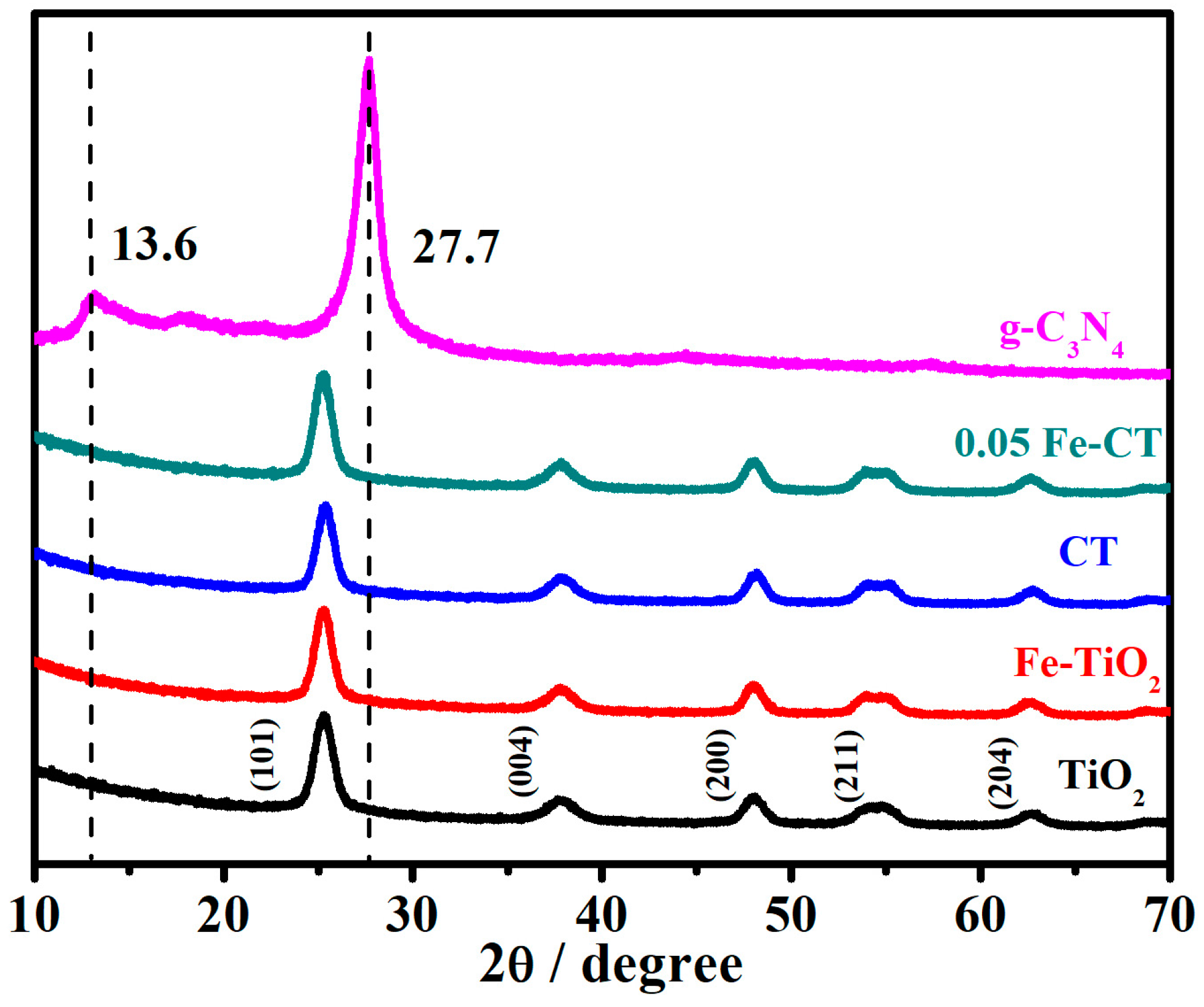
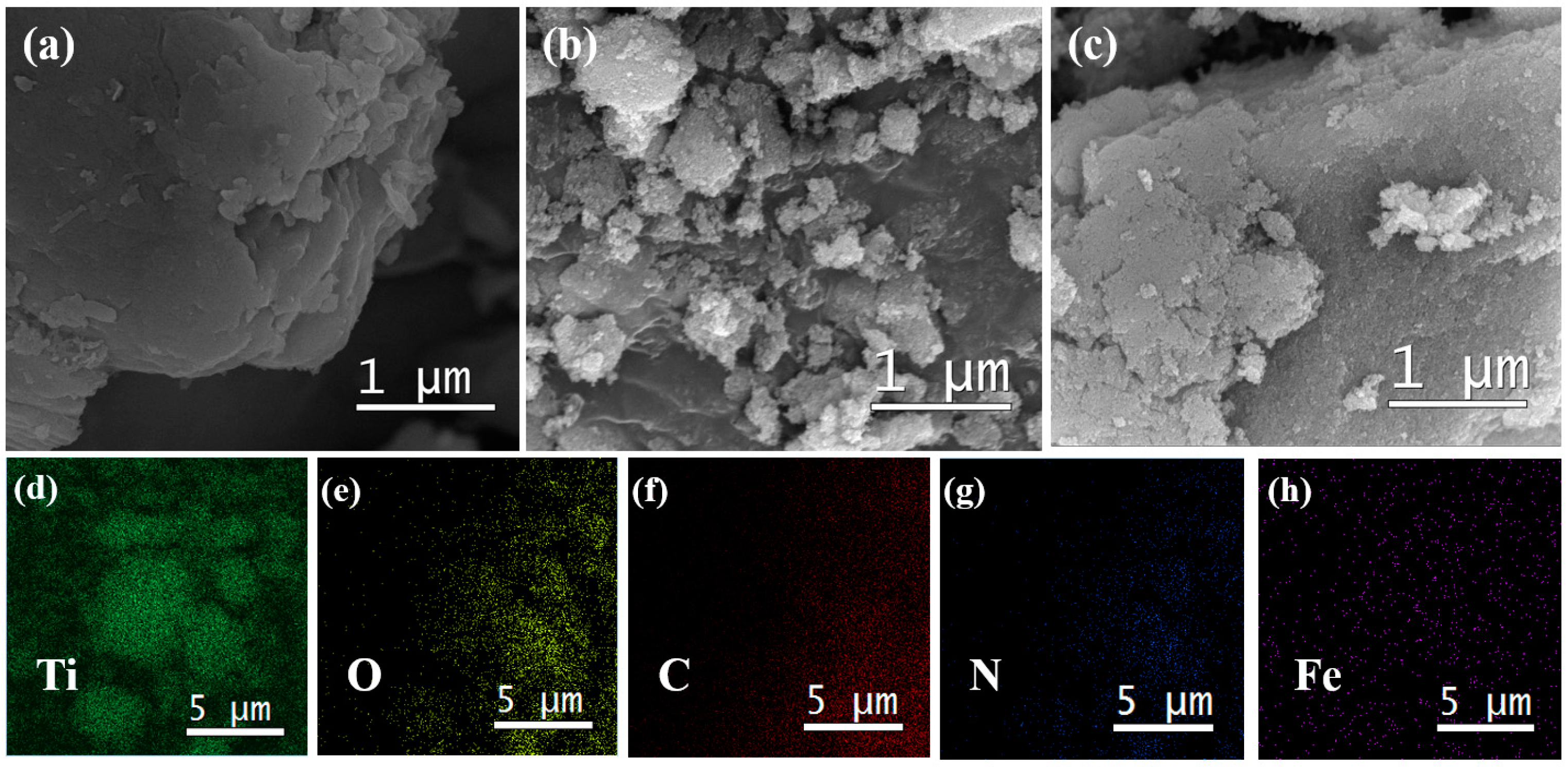
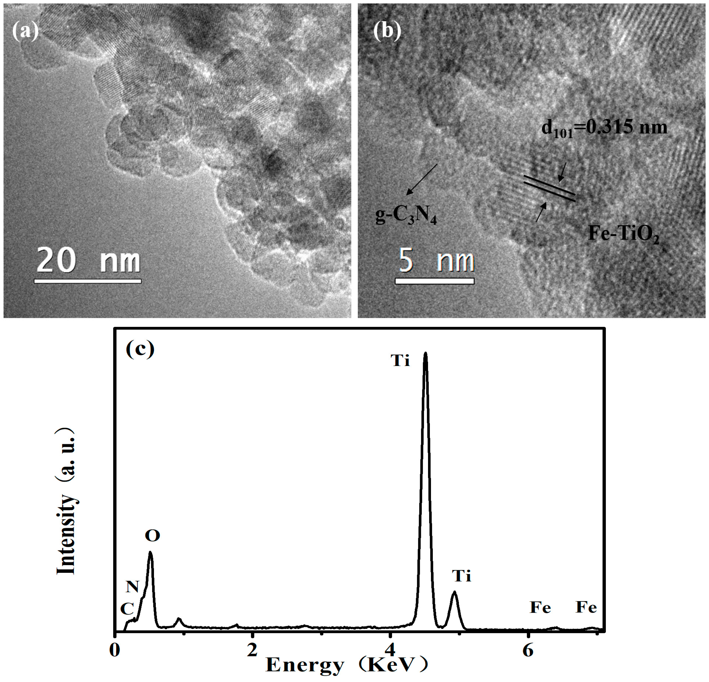
2.1. Phase Structures and Morphology

Figure 1 shows the XRD patterns of the TiO2, Fe-TiO2, g-C3N4/TiO2 (CT), 0.05Fe-CT, and g-C3N4 samples. It can be seen that all of the TiO2-based samples exhibit identical diffraction patterns. The 2θ peaks observed at 25.3°, 37.8°, 48.0°, 54.0°, and 62.4° were well-matched with the standard data and correspond to the (101), (004), (200), (204), and (211) crystal planes of anatase TiO2, respectively [27]. The two prominent diffraction peaks observed at 13.6° and 27.7° for pure g-C3N4 could be attributed to the diffraction patterns of the (100) and (002) crystal planes, respectively [28]. No peak corresponding to the characteristics of g-C3N4 was observed in either the CT or 0.05Fe-CT samples, and this might be due to the relatively poor crystallization and less content of g-C3N4 within the composites [29]. In addition, there is no obvious change in the peaks of anatase TiO2 in both the composites, which indicates that neither the coupling of g-C3N4 nor the Fe-doping affects the phase structure of TiO2.
The images of SEM and TEM taken for the synthesized samples are displayed in Figure 2 and Figure 3, respectively. The pure g-C3N4 sample exhibits a layered structure with a smooth surface that can be clearly seen in Figure 2a. This layered structure is expected to provide more sites for the growth of Fe-TiO2 nanoparticles. Figure 2b reveals that Fe-TiO2 materials consist of the aggregation of small nanocrystals. From the result shown in Figure 2c, it is found that the layered structure remains intact upon the incorporation of Fe-TiO2 nanoparticles; moreover, the surface of g-C3N4 becomes slightly rough due to the formation of Fe-TiO2 nanoparticles, suggesting that at least two semiconductors are in absolute physical contact with each other, which is the premise for the probable formation of either heterojunction or Z-scheme composites. Additionally, Energy Dispersive X-ray Spectroscopy (EDX) mapping of the composite shown in Figure 2d–h confirms the presence of Ti, O, C, N, and Fe elements in the 0.05Fe-CT sample. These results along with those of XRD and SEM suggest that Fe-TiO2 nanoparticles are successfully loaded on the surface of g-C3N4.
From the high resolution transmission electron microscopy (HR-TEM) image of the 0.05Fe-CT sample as shown in Figure 3a,b, a distribution of TiO2 nanoparticles with the size of ~5 nm on the surface of g-C3N4 was confirmed. The lattice spacing of TiO2 nanoparticles was found to be 0.351 nm, which matches with the (101) plane. The corresponding EDX pattern shows the existence of C, N, Ti, O, and Fe elements, which was in accordance with the results of the EDX mapping discussed earlier.
As seen in Figure 4a, the Fourier Transform Infrared (FTIR) spectrum for the g-C3N4, TiO2, CT, and 0.05Fe-CT samples shows strong bands in the region of 450–4000 cm−1. For g-C3N4, the bands observed around 1100–1650 cm−1 could be assigned to C-N and C=N stretching vibrations; the band at 810 cm−1 corresponds to s-triazinering vibrations; and the band around 3000–3300 cm−1 is correlated to N-H stretching vibration modes [30,31,32,33]. For the TiO2 sample, the band observed around 500–700 cm−1 could be accounted for with Ti-O stretching and Ti-O-Ti bridging stretching modes; and the bands at 1630 and 3400 cm−1 are correlated to the H-O-H bending stretch of surface-adsorbed water and its hydroxyl groups, respectively [34]. The characteristic bands observed for g-C3N4 and TiO2 appeared in both the CT and 0.05Fe-CT composite samples too.
As seen in Figure 4b, the optical property of the 0.05Fe-CT, CT, pure TiO2, and g-C3N4 samples was measured by UV-vis diffuse reflectance spectroscopy. The UV-vis DRS spectra of 0.05Fe-CT and CT are quite similar to that of pure TiO2, except for a slight movement of their main absorption edges toward the visible light region. In addition, upon the incorporation of g-C3N4, i.e., for the CT sample, a red shift moving up to 443 nm was observed, which indicates a reduced bandgap absorption edge of 2.80 eV estimated from 1240/λ (λ describes wavelength) [35]. Further, upon the doping of Fe to the CT sample, the light absorption of 0.05Fe-CT was extended to a still longer wavelength region and the appearance of the highest red shift, to a maximum of 461 nm (2.69 eV), was observed. These observations clearly indicate that the incorporation of composite material and the doping of Fe could graft a photocatalyst with the ability to utilize visible light effectively.
EPR as a highly sensitive spectroscopic technique for examining paramagnetic species can give valuable information about the lattice site wherein a paramagnetic doping ion is located. This technique can detect Fe ions to an extent of even less than 0.01 wt % in metal-oxide matrices [36]. The EPR spectra of TiO2, CT, 0.01Fe-CT, 0.03Fe-CT, 0.05Fe-CT, and 0.06Fe-CT are depicted in Figure 5. At high magnetic field, a symmetrical EPR signal is observed at g = 2.004 for both TiO2 and CT as well, which is an identification of the trapping of electrons on oxygen vacancies [37]. In addition, the EPR signal of CT is in accordance with that of TiO2, which strongly indicates that the presence of CNs has no influence on the phase structure of the TiO2. For the xFe-CT samples, unsymmetrical signals are observed at g = 1.99, which can be assigned to the fact that the Fe3+ is substituted for Ti4+ in the octahedral surroundings/atmosphere [37,38], otherwise it could simply be an overlapping of the two kinds of EPR signals. Further, as no signal at other g values was observed, the existence of Fe ions as Fe2O3-type clusters (g = 2.16) could not be possible [39,40]. It is worth noting that the intensity of signals at g = 1.99 of xFe-CT samples as shown in Figure 5a increases with increasing Fe3+ content, which indicates that the substitution of Fe3+ for Ti4+ in the TiO2 lattice was effectively accomplished by a hydrothermal approach of simply increasing the iron content in the solution mixture. As seen in Figure 5b, the EPR spectra at low magnetic field exhibited very weak signals of g value at 4.29, which suggests that Fe3+ was located in a strongly distorted rhombic environment [40]. It is clear that the specific signals of EPR spectra at both high and low magnetic field confirmed the successful incorporation of Fe3+ into the crystal lattice of TiO2 by a one-step hydrothermal method.
In order to examine the chemical states of elements involved in the as-prepared samples, XPS measurements were performed. The comparison of the Ti 2p spectra for samples TiO2, Fe-TiO2, and 0.05Fe-CT is shown in Figure 6a. The Ti 2p3/2 and Ti 2p1/2 peak positions of the TiO2 sample were 458.55 eV and 464.25 eV, whereas they shifted to a higher binding energy of 458.65 eV and 467.35 eV for the Fe-TiO2 and 0.05Fe-CT samples, respectively. The small shifts of binding energy might be due to the effect of the Fe3+ in the interstitial and/or substitutional site in the TiO2 crystal lattice and formed the Ti-O-Fe bonds in the crystal lattice [41,42]. Due to the low doping level, the signals of Fe were too weak to be observed (not shown). As for the O 1s spectra presented in Figure 6b, two peaks of the binding energy at 529.95 and 532 eV for the 0.05Fe-CT sample were associated with the O2 in TiO2 and the -OH terminal on the surface [42]. For the 0.05Fe-CT sample, the formation of the new Ti-O-Fe bonds in the crystal lattice might change the electron densities of Ti4+ cations and O2 anions, which caused a slightly higher shift of O 1s peaks compared to those for TiO2 at 529.75 and 531.65 eV, respectively, and which might be a cause for the enhanced photocatalytic activity [42,43].
From the XPS spectra of C 1s in Figure 6c, three peaks centered at 285, 286.2, and 288.9 eV can be observed in all three samples. The main C 1s corresponds to adventitious carbon species presenting a band located at 284.4 eV [44]. The small shoulder at 286.4 and 288.9 eV could be accounted for with the C-N-C and C-(N)3 groups of g-C3N4, respectively [26,45,46]. In addition, the regional spectrum of N 1s for 0.05Fe-CT as seen in Figure 6d could be fitted into two peaks at 399.2 and 400.4 eV, with the former ascribed to C-N=C [34] and the latter to the N-(C)3 of the g-C3N4 [26]. No peak concerning chemical interaction between Ti and C (Ti-C) or N (Ti-N) is seen for the 0.05Fe-CT sample in the XPS (Figure 6c,d) spectra. Taking into account of the results of FTIR, SEM, and DRS studies together, the deposition of g-C3N4 could only be on the surface of the Fe-TiO2, and there was a chemical reaction between them as no apparent characteristic Ti-C(N) coordination peaks were seen.

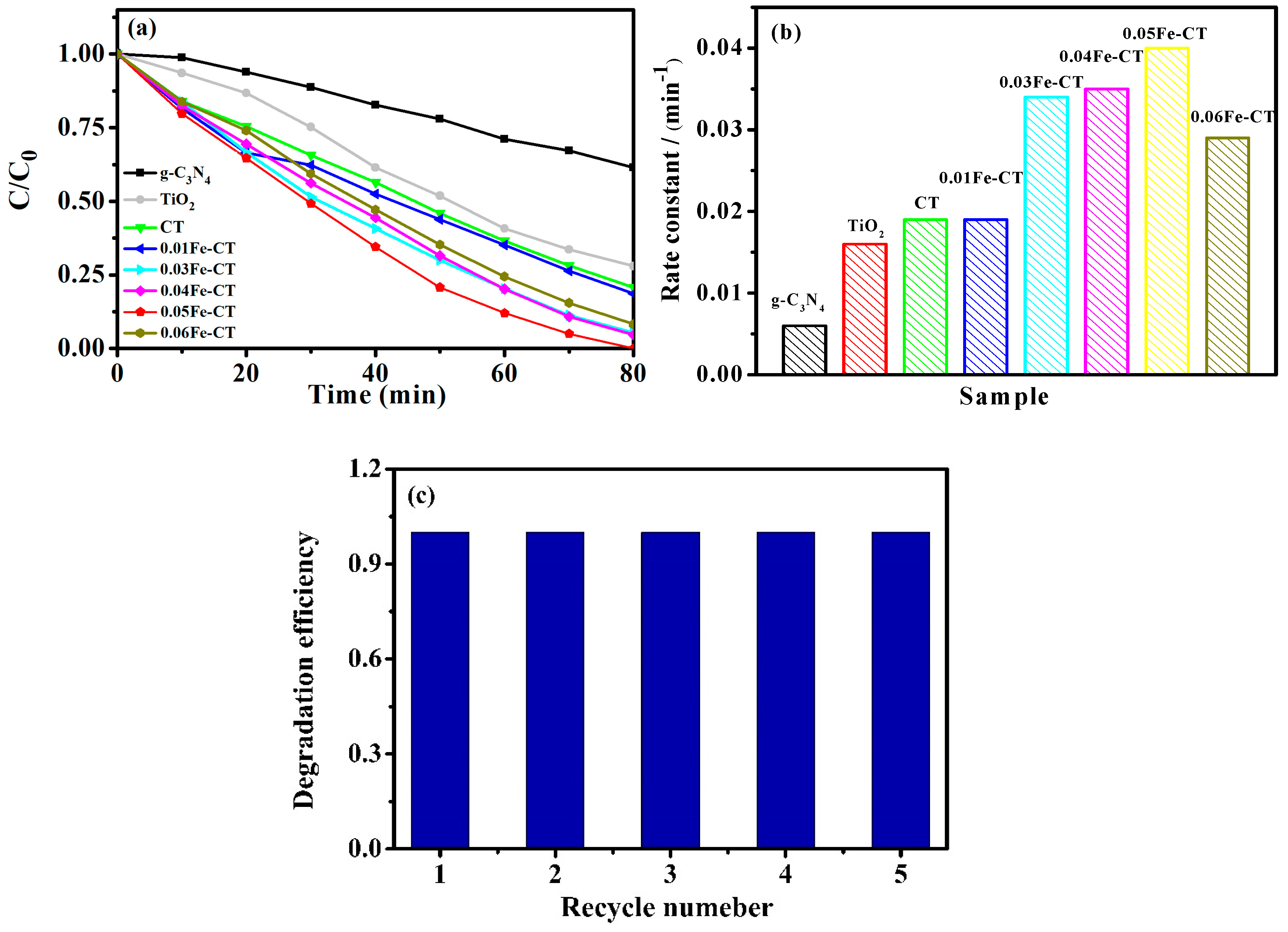
2.2. Photocatalytic Activity Test

The photocatalytic activity of the prepared samples was evaluated in terms of photodegradation of phenol with a concentration of 10 mg dm−3 under visible light irradiation. Phenol was chosen as a model pollutant because it is the basic molecule of phenolic compounds, which are known to be highly toxic, persistent, and biorecalcitrant, widely used in preservative, herbicide, and pesticide products, and being considered to be a grave threat to the health of humankind [47]. The study was carried out under similar experimental conditions using the respective photocatalytic materials.
The change of concentration of phenol during the photodegradation process under visible light irradiation is shown in Figure 7a. The decomposition of phenol was achieved to an extent of 38.6% and 72% at 80 min for pure g-C3N4 and TiO2, respectively. The effective photodegradation of phenol observed (79.2%) in the case of g-C3N4 (CT) could account for the impact of the hybrid structure on enhancing the photocatalytic activity of the material. Upon the incorporation of Fe3+ into CT, i.e., xFe-CT, the observed photocatalytic activity was higher compared to that of TiO2 and CT, separately. Furthermore, the photocatalytic activity of the xFe-CT increased as the content of Fe3+ increased initially from 0.01% to 0.05%, and thereupon there was a decline trend up to 0.06%. Additionally, the 0.05Fe-CT sample showed a highest photocatalytic activity of complete degradation of phenol at 80 min under visible light irradiation. These findings confirmed that the enhanced photocatalytic activity of the composite materials cause a synergetic effect of both g-C3N4 and Fe3+.
The degradation of phenol follows a pseudo-first-order reaction [28,48] of l n ( c t c 0 ) = k t , where C0 is the initial concentration of phenol, Ct is the concentration of phenol at time t, and k is kinetic constant. The kinetic constants (k) of all samples were calculated and are given in Figure 7b. It is 0.019 min−1 for CT composites higher than that of either pure g-C3N4 (the k value was 0.0044 min−1) or TiO2 (the k value was 0.016 min−1). When Fe3+ ions were introduced, an enhanced photocatalytic activity was observed from all of the g-C3N4/Fe-TiO2 composites and the rate constants were 0.016 min−1, 0.034 min−1, 0.035 min−1, 0.04 min−1, and 0.029 min−1 for the samples of 0.01Fe-CT–0.06Fe-CT, respectively. It was found that the incorporation of Fe3+ enhanced the photocatalytic activity of the obtained heterojunctions, and the highest performance was observed in 0.05Fe-CT.
The stability of 0.05Fe-CT was examined by catalyst recycling experiments under similar operating conditions for the photodegradation of phenol. After each cycle, the catalyst was separated by centrifugation, washed with ethanol and millipore deionized water, then dried and reused for a fresh run of photodegradation of phenol with a concentration of 10 mg dm−3. As seen in Figure 7c, no obvious decline in the degradation efficiency was observed after five cycles, suggesting that the combination of g-C3N4 and Fe-TiO2 has high-level photocatalytic stability for phenolic compound degradation.

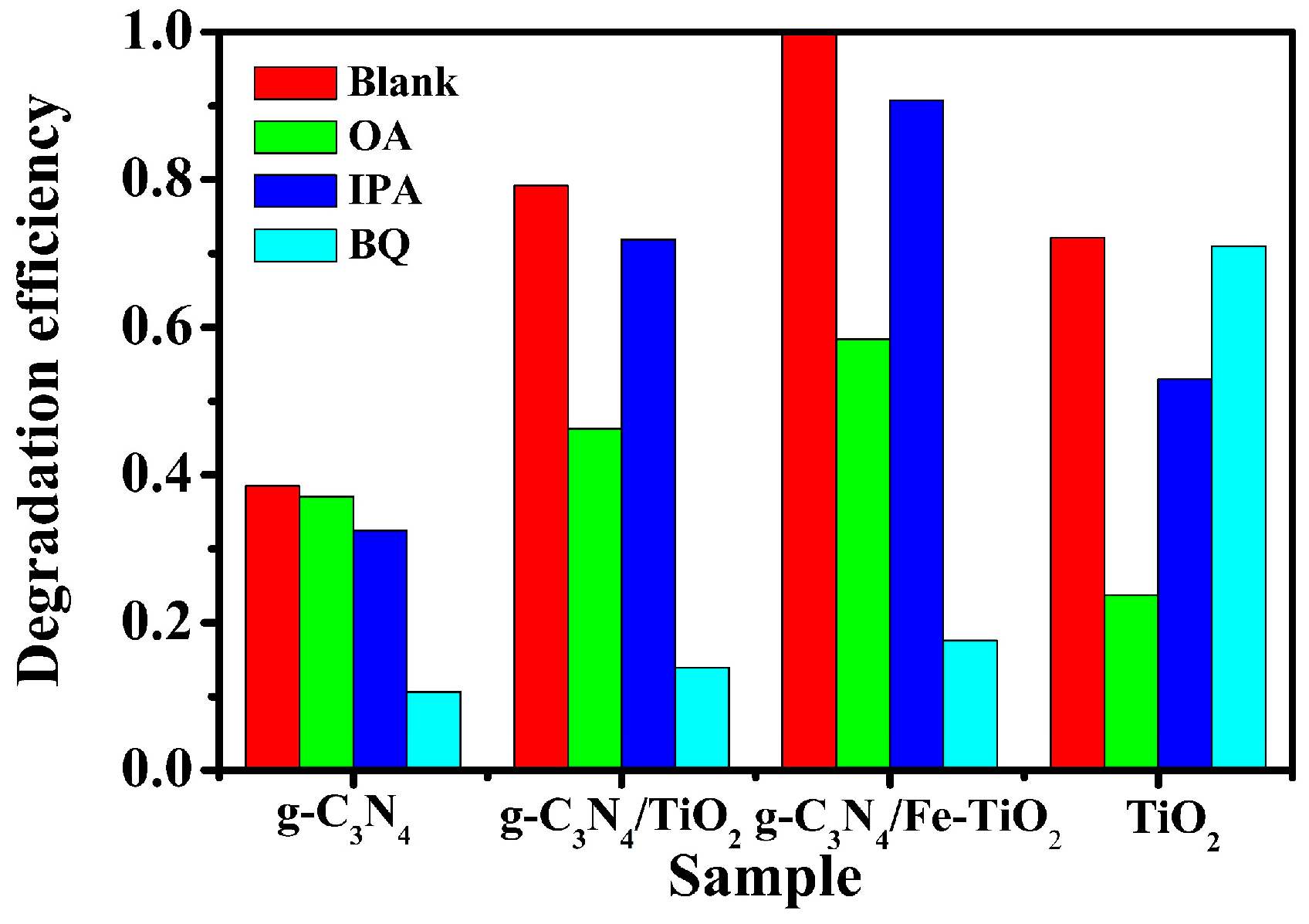
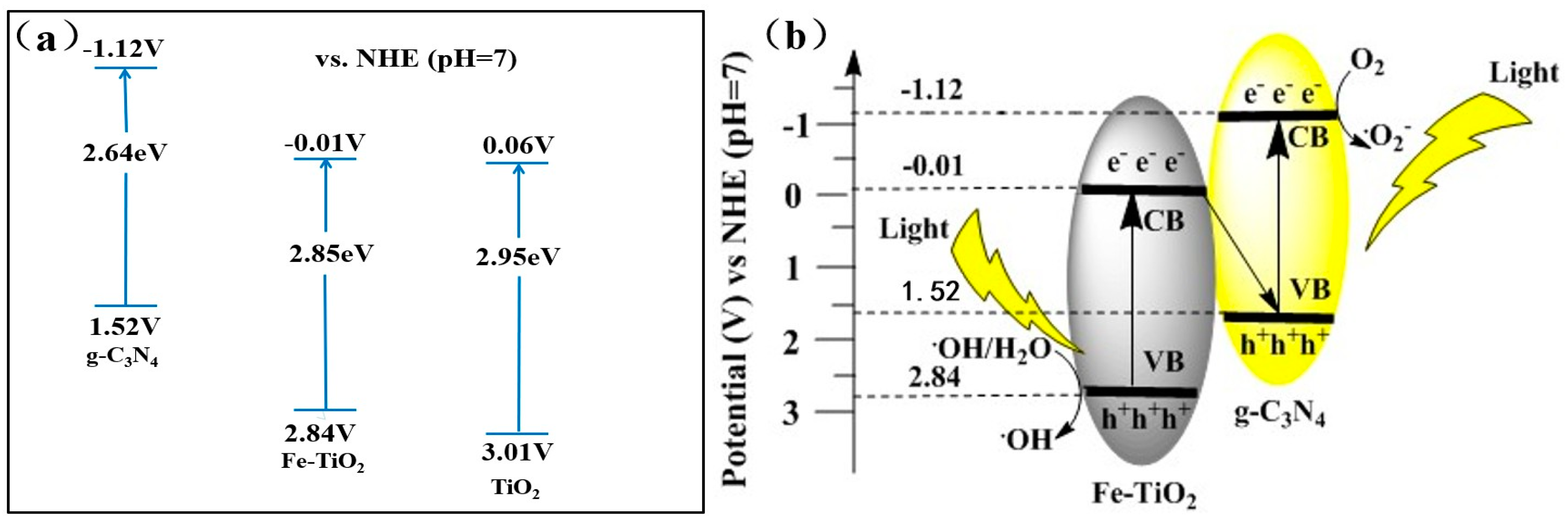
2.3. Photocatalytic Mechanism

In order to elucidate the photocatalytic mechanism of Fe-CT composites, the main active species generated over g-C3N4, CT, 0.05Fe-CT, and TiO2 were quantified by adding a suitable scavenger during the photocatalytic degradation of phenol. The reactive species corresponding to both g-C3N4 and Fe-TiO2 were nullified as references, so that the reactive species of 0.05Fe-CT alone could be figured out. The scavengers used in this study were sodium oxalate (OA, 0.5 mmol dm−3), p-benzoquinone (BQ, 0.5 mmol dm−3), and isopropanol (IPA, 1 mmol dm−3) against photogenerated holes (h+) [49], superoxide anion radicals (•O2) [18], and hydroxyl radicals (•OH) [49], respectively. It needs to be mentioned that the applied concentration of each scavenger did not cause any removal of phenol in the respective control experiment [23].
As shown in Figure 8, for pure g-C3N4, the addition of OA caused a slight decrease of the photocatalytic efficiency from 38.6% to 37.1% at 80 min, which indicates that h+ was not the major reactive specie; the introduction of IPA caused a decrease to 32.5%, which indicates that •OH made a considerable contribution towards the photocatalytic degradation. When BQ was added into the reaction solution, the degradation efficiencies of phenol showed a significant fall to 10.1%. From these results, it is very clear that •O2 is the major reactive specie in the photocatalytic reaction of pure g-C3N4. The order of influence was •O2 > •OH > h+.
For the TiO2, the efficiency of phenol degradation was shown to be 72.1% when no scavenger was added. With the addition of OA and IPA into the reaction solution of a separate run, the photocatalytic efficiency of phenol degradation decreased to 23.8% and 52.9%, respectively. In the presence of BQ, the degradation rate of phenol was slightly decreased to 71%. Obviously, the major reactive species for pure TiO2 are h+ and •OH.
As seen in Figure 8, for the g-C3N4/TiO2 photocatalytic system, the degradation efficiency of phenol was inhibited in the order BQ > OA > IPA when these three scavengers were added in the separate run, which indicates that •O2, •OH, and h+ were all of the active species generated in the g-C3N4/TiO2 photocatalytic system.
It is clear in Figure 8 that the photocatalytic efficiency of phenol for the 0.05Fe-CT photocatalyst was 100% at 80 min without any scavengers. With the addition of scavenger IPA, BQ, and OA in the separate run, the photocatalytic efficiencies of phenol decreased to 90.1%, 58.5%, and 17.6%, respectively. The inference is that both g-C3N4/TiO2 and Fe-CT showed an identical trend in the presence of scavengers, the major reactive species were •O2 as well as h+ in the photocatalytic reaction of g-C3N4/Fe-TiO2, and the order of influence was •O2 > h+ >•OH.
To further determine the photocatalytic mechanism of Fe-CT composites, a quantitative estimation of •OH was carried out by the photoluminescence (PL) method using terephthalic acid (TA) as a probe molecule during the photocatalysis process. The PL signals of g-C3N4, TiO2, Fe-TiO2, CT, and 0.05Fe-CT samples recorded at 80 min of the photocatalysis process are shown in Figure 9a. It could be easily understood that no •OH was generated during the photocatalysis process using g-C3N4 as there was no corresponding PL signal. The absence of •OH radicals in the photocatalysis process of g-C3N4 could be well-explained by taking into account the position of the VB edges of g-C3N4 and the actual potential of the OH/•OH couple (+1.83 V/+2.7 V) (versus NHE) formation. Thus, the photogenerated holes on the surface of g-C3N4 were not strong enough to oxidize the OH or H2O into •OH [26,50]. However, the formation of •OH was observed in the TiO2, Fe-TiO2, CT, and 0.05Fe-CT samples, among which 0.05Fe-CT showed the greatest quantity of •OH generation, which confirms the Z-scheme of transferring photoexcited charge carriers between g-C3N4 and Fe-TiO2. Otherwise, if 0.05Fe-CT worked only under the general heterojunction system, the oxidation ability of the composite would have been the same as that of g-C3N4, wherein the production of •OH is not possible.
As seen in Figure 9b, the linear potential part of the Mott–Schottky plot based on impedance measurements was used to determine the flat-band positions of the samples [51]. The positive slope of the straight lines indicates that both TiO2 and Fe-TiO2 are n-type semiconductors, i.e., the flat-band potential [52] of the samples approximately equates to the lowest potential of the CB. Thus, the CB level of TiO2 and Fe-TiO2 are measured to be ca +0.05 V (versus NHE) and −0.01 V, respectively. The negative shift of flat-band potentials (Efb) after Fe doping suggests a similar shift of the Fermi level, which facilitates the charge separation at the semiconductor/electrolyte interface [53].
These accumulated electrons in the CB of TiO2 (Figure 10a) could not effectively reduce the O2 to yield •O2 due to its CB being less negative than that of •O2/O2 potential (−0.28 V versus NHE) [54]. The VB of TiO2 is more positive than that of H2O/•OH potential (+2.7 V versus NHE) and capable enough to oxidize H2O to form •OH [34]. Our experiment mentioned above has also confirmed that h+ but not the •O2 generated was the major reactive specie in the photocatalytic degradation of the phenol molecule for pure TiO2; on the other hand, the VB levels (ca. +1.58 V) of g-C3N4 are not positive enough to drive the oxidation of H2O to form •OH, but its CB level (ca. −1.12 V) is negative enough to reduce O2 to produce •O2 [18,49]. Also, it has been observed that the •O2 was a major reactive specie in the photocatalytic reaction for pure g-C3N4. For the composite of CT, the formation of •OH and the significant contribution of both h+ and •O2 in the photocatalytic reaction showed that the composite followed the Z-scheme. If the charge carriers of the CT were transferred as per the so-called usual model, the electrons in the CB of g-C3N4 would have migrated to the CB of TiO2 and accumulated over there, which could possibly not reduce the O2 to yield •O2; holes in the VB of TiO2 would migrate to the VB of g-C3N4, which could not oxidize OH/H2O to give •OH.
For the Fe-doped TiO2 (Fe-TiO2), a prominent decrease in the band gap and a red shift of the threshold absorption were observed in UV-vis DRS analysis. In addition, the extent of doping of Fe3+, which actually existed in the form of O••v in the band gap of TiO2, could enhance the photocatalytic activity of the material in the visible region [55,56]. As a result, the Fe-TiO2 showed higher photocatalytic activity and a greater quantity of •OH generation than those of TiO2.
Based on the above results, the Z-scheme mechanism of the g-C3N4/Fe-TiO2 composites is illustrated in Figure 10b in detail. Due to their narrow band gaps, both g-C3N4 and Fe-TiO2 can be easily excited to yield photogenerated electron–hole pairs under visible-light irradiation. Since both the CB and VB positions of Fe-TiO2 are lower than those of g-C3N4, the photogenerated electrons (e) in the CB of Fe-TiO2 tend to transfer and recombine with the photogenerated holes (h+) in the VB of g-C3N4. The photogenerated holes left behind in the VB of Fe-TiO2 can directly oxidize phenol into harmless metabolite products. Simultaneously, the remaining photogenerated electrons in the CB of g-C3N4 can reduce the adsorbed O2 to yield •O2, which is again a powerful oxidative species for phenol degradation. The g-C3N4/Fe-TiO2 composites following a Z-scheme mechanism enable a fast separation and transfer of the photogenerated electron−hole pairs and in turn show strong oxidation and reduction abilities for the efficient photocatalytic degradation of organic pollutants.

3. Materials and Methods

3.1. Chemical and Material

Analytical grade (AR) chemicals viz. Ferric nitrate (Fe(NO3)3·9H2O), tetra-butyl titanate (TBOT), absolute ethyl alcohol (C2H6O), nitric acid (HNO3), melamine, isopropanol, 5% Nafion, phenol sodium oxalate (OA), p-benzoquinone (BQ), and isopropanol were purchased from Sinopharm Chemical Reagent CO. Ltd., Shanghai, China and used as received. Millipore deionized water was used for preparing the stock solutions and the entire experimental part.

3.2. Catalyst Preparation

The g-C3N4 was synthesized from melamine by a direct heating step. Five grams (5 g) of melamine powder, taken in an alumina crucible, was placed in a muffle furnace and heated at 500 °C for 2 h. After cooling down to room temperature, the yellowish product was ground into powder form and again heated in a muffle furnace at 500 °C for another 2 h.
The composite particles were synthesized through a one-step hydrothermal process. A 20 mL volume of TBOT was gradually dropped into a mixture containing 167.5 mL of C2H6O, 5.0 mL specific concentration of Fe(NO3)3, 1.25 mL of HNO3, and 0.047 g of g-C3N4 under vigorous stirring, and the stirring process continued for another 1 h. Then, the mixture was transferred into a 500 mL teflon-lined stainless steel autoclave vessel and it was kept at 200 °C for 6 h. After the hydrothermal process, the precipitate was centrifuged, washed several times with ethanol and water, dried at 80 °C overnight, and ground well. The as-prepared samples were denoted as xFe-CT, where x stands for the weight percentage of Fe (x = 0.01, 0.03, 0.04, 0.05, 0.06) with respect to TiO2 content, and CT denotes the g-C3N4/TiO2.

3.3. Characterization

The phase purity and crystal structure of the as-obtained samples were examined by the XRD technique using Rigaku Ultima IV X-ray diffraction (Rigaku Corporation, Tokyo, Japan) equipped with Cu Kα radiation (40 kV, λ = 1.5406 Å). The 2θ scanning angle range was 20–80° with a step of 0.05 s−1. The morphology was examined using a field emission scanning electron microscope (FE-SEM, NANOSEM 450, FEI Corporation, Eindhoven, The Netherlands) operating at an accelerating voltage of 30 kV. TEM characterizations were done using an H-7000FA microscope (Hitachi, Tokyo, Japan) operating at the accelerating voltage of 75 kV. The UV-visible spectrum was obtained on a UV-2550 UV-visible spectrophotometer (Shimadzu Corporation, Kyoto, Japan) at room temperature and the spectrum range analyzed was 200–800 nm. The infrared absorption spectra were measured in a frequency range from 500 cm−1 to 4000 cm−1 on a Bruker V-70 FTIR spectrophotometer (Bruker, Karlsruhe, Germany). The X-band electron paramagnetic resonance (EPR) spectra were recorded at room temperature using a Bruker A300-10/12 EPR spectrophotometer (Bruker Corporation, Karlsruhe, Germany). The microwave frequency was fixed at 100 KHz, the power was 10 mW, and the field modulation ranged between 1.3–1.9 G and 3.2–3.7 G. The X-ray photoelectron spectroscopy (XPS) data were collected by an Axis Ultra instrument (Kratos Analytical, Manchester, UK) under an ultra-high vacuum (<10−8 Torr) using a monochromatic Al Ka X-ray source ( = 1486.6 eV) operating at 150 W.
Mott–Schottky plots have been investigated on an electrochemical workstation (CS310, CorrTest, Wuhan, China) under a three-electrode configuration by employing TiO2 or Fe-TiO2, Ag/AgCl, and Pt mesh as the working, reference, and counter electrode, respectively. Herein, the working electrodes had undergone a two-step treatment. Initially, 5 mg of synthesized sample was mixed with 800 μL of isopropanol, followed by 200 μL of millipore deionized water, and finally 20 μL of 5% Nafion, and then the mixture underwent an ultrasonication treatment; 6 μL of the mixture was dropped onto glassy carbon electrode and dried in an air environment. The supporting electrolyte used was Na2SO4 with a concentration of 0.5 mol dm−3. The potential scanning measurements for the electrode were performed from −0.2 V to 0.8 V in dark conditions, and the impedance-potential characteristics of the electrode were recorded at a frequency of 10 Hz.

3.4. Photocatalytic Activity Measurement

The photocatalytic experiment on phenol degradation under visible light was carried out in a glass container having a volume capacity of 200 mL to evaluate the activity of the g-C3N4/Fe-TiO2 composites. The light source was a 300 W PLS-SXE 300 xenon lamp (Perfect light, Wuhan, China) with a 400 nm cut filter to remove the UV irradiation that was suspended over a height of 10 cm from the reaction solution surface. Typically, 5 mg of as-prepared photocatalyst was added into 50 mL of phenol-contaminated (10 mg dm−3) working solution. The glass container was placed in an ice-water bath, and the entire setup was placed on a magnetic stirrer operated at a constant stirring rate of 380 rpm. Prior to light irradiation, the suspension was stirred for 1 h to establish an adsorption/desorption equilibrium between phenol and photocatalyst under dark conditions. After visible light irradiation for a defined period of time (every 10 min), the reaction solution (1 mL) for analysis was siphoned out, and then the suspensions were removed by centrifugation and the clear supernatant solution was used for analysis. The concentration of phenol was measured by high performance liquid chromatography (HPLC) (Shimadzu, Kyoto, Japan) equipped with a UV detector and a C18 reverse-phase column (4.6 mm i.d. ×150 mm, Agilent, CA, USA). The mobile phase used in the HPLC was water and methanol (volumetric ratio of 50:50), and the injection volume of the sample was 20 μL with a flow rate of 0.5 mL min−1. The wavelength of the UV absorbance detector was fixed at 270 nm.
The quantity of •OH in the photocatalytic process was determined by the photoluminescence (PL) technique using terephthalic acid as a probe molecule. Terephthalic acid reacts with •OH to produce a highly fluorescent product 2-hydroxy terephthalic rapidly and specifically, which reflects as the PL signal at 425 nm excited by 315 nm of light. Detailed experimental information is given in our previous work [57].

4. Conclusions

The photocatalytic g-C3N4/Fe-TiO2 composite was successfully synthesized by a one-step hydrothermal process and found to exhibit excellent photocatalytic activity and stability for the photocatalytic degradation of organic pollutants. The composite with an optimum content of Fe3+ of 0.05 wt % exhibits the highest photocatalytic activity towards phenol degradation owing to a stronger spectral absorption of visible light wavelengths, an enhancement in the carrier density, and a decrease in the charge transfer resistance between the interface of solid and electrolyte. The formation of Z-scheme g-C3N4/Fe-TiO2 heterojunctions possesses a higher efficiency of charge separation and transfer as well as stronger oxidation and reduction abilities. This work may give new insight into the development of Z-scheme composite photocatalysts, which is of a great interest to the scientific community for photocatalysis.

Acknowledgments

This work was supported by the International Science & Technology Cooperation Program of China (Nos. 2013DFG50150 and 2016YFE0126300) and the Innovative and Interdisciplinary Team at HUST (2015ZDTD027). The authors thank the Analytical and Testing Center of HUST for the use of SEM, XRD, TEM, FTIR, and DRS equipment.

Author Contributions

Yanrong Zhang and Muthu Murugananthan conceived and designed the experiments; Jie Gu performed the experiments; and Zedong Zhu contributed analysis tools and wrote the paper.

Conflicts of Interest

The authors declare no conflict of interest.

References

  1. Asahi, R.; Morikawa, T.; Ohwaki, T.; Aoki, K.; Taga, Y. Visible-Light Photocatalysis in Nitrogen-Doped Titanium Oxides. Science 2001, 293, 269–271. [Google Scholar] [CrossRef] [PubMed]
  2. Tong, H.; Ouyang, S.; Bi, Y.; Umezawa, N.; Oshikiri, M.; Ye, J. Nano-photocatalytic materials: Possibilities and challenges. Adv. Mater. 2012, 24, 229–251. [Google Scholar] [CrossRef] [PubMed]
  3. Wang, G.; Wang, H.; Ling, Y.; Tang, Y.; Yang, X.; Fitzmorris, R.C.; Wang, C.; Zhang, J.Z.; Li, Y. Hydrogen-treated TiO2 nanowire arrays for photoelectrochemical water splitting. Nano Lett. 2011, 11, 3026–3033. [Google Scholar] [CrossRef] [PubMed]
  4. Zhou, W.; Liu, Q.; Zhu, Z.; Zhang, J. Preparation and properties of vanadium-doped TiO2 photocatalysts. J Phys. D Appl. Phys. 2010, 43, 035301. [Google Scholar] [CrossRef]
  5. George, S.; Pokhrel, S.; Ji, Z.; Henderson, B.L.; Xia, T.; Li, L.; Zink, J.I.; Nel, A.E.; Madler, L. Role of Fe doping in tuning the band gap of TiO2 for the photo-oxidation-induced cytotoxicity paradigm. J. Am. Chem. Soc. 2011, 133, 11270–11278. [Google Scholar] [CrossRef] [PubMed]
  6. Colón, G.; Maicu, M.; Hidalgo, M.C.; Navío, J.A. Cu-doped TiO2 systems with improved photocatalytic activity. Appl. Catal. B Environ. 2006, 67, 41–51. [Google Scholar] [CrossRef]
  7. Ohno, T.; Murakami, N.; Tsubota, T.; Nishimura, H. Development of metal cation compound-loaded S-doped TiO2 photocatalysts having a rutile phase under visible light. Appl. Catal. A Gen. 2008, 349, 70–75. [Google Scholar] [CrossRef]
  8. Samiolo, L.; Valigi, M.; Gazzoli, D.; Amadelli, R. Photo-electro catalytic oxidation of aromatic alcohols on visible light-absorbing nitrogen-doped TiO2. Electrochim. Acta 2010, 55, 7788–7795. [Google Scholar] [CrossRef]
  9. Yu, J.; Qi, L.; Jaroniec, M. Hydrogen Production by Photocatalytic Water Splitting over Pt/TiO2 Nanosheets with Exposed (001) Facets. J. Phys. Chem. C 2010, 114, 13118–13125. [Google Scholar] [CrossRef]
  10. Seh, Z.W.; Liu, S.; Low, M.; Zhang, S.Y.; Liu, Z.; Mlayah, A.; Han, M.Y. Janus Au-TiO2 photocatalysts with strong localization of plasmonic near-fields for efficient visible-light hydrogen generation. Adv. Mater. 2012, 24, 2310–2314. [Google Scholar] [CrossRef] [PubMed]
  11. Choi, W.; Termin, A.; Hoffmann, M.R. The Role of Metal Ion Dopants in Quantum-Sized TiO2: Correlation between Photoreactivity and Charge Carrier Recombination Dynamics. J. Phys. Chem. 1994, 98, 13669–13679. [Google Scholar] [CrossRef]
  12. Dai, K.; Lu, L.; Liang, C.; Liu, Q.; Zhu, G. Heterojunction of facet coupled g-C3N4/surface-fluorinated TiO2 nanosheets for organic pollutants degradation under visible LED light irradiation. Appl. Catal. B Environ. 2014, 156–157, 331–340. [Google Scholar] [CrossRef]
  13. Takahashi, Y.; Tatsuma, T. Oxidative Energy Storage Ability of a TiO2-Ni(OH)2 Bilayer Photocatalyst. Langmuir 2005, 21, 12357–12361. [Google Scholar] [CrossRef] [PubMed]
  14. Su, J.; Guo, L.; Bao, N.; Grimes, C.A. Nanostructured WO3/BiVO4 heterojunction films for efficient photoelectrochemical water splitting. Nano Lett. 2011, 11, 1928–1933. [Google Scholar] [CrossRef] [PubMed]
  15. Zhang, Y.C.; Yao, L.; Zhang, G.; Dionysiou, D.D.; Li, J.; Du, X. One-step hydrothermal synthesis of high-performance visible-light-driven SnS2/SnO2 nanoheterojunction photocatalyst for the reduction of aqueous Cr(VI). Appl. Catal. B Environ. 2014, 144, 730–738. [Google Scholar] [CrossRef]
  16. Dai, X.; Xie, M.; Meng, S.; Fu, X.; Chen, S. Coupled systems for selective oxidation of aromatic alcohols to aldehydes and reduction of nitrobenzene into aniline using CdS/g-C3N4 photocatalyst under visible light irradiation. Appl. Catal. B Environ. 2014, 158–159, 382–390. [Google Scholar] [CrossRef]
  17. Arai, T.; Yanagida, M.; Konishi, Y.; Iwasaki, Y.; Sugihara, H.; Sayama, K. Efficient Complete Oxidation of Acetaldehyde into CO2 over CuBi2O4/WO3 CompositePhotocatalyst under Visible and UV Light Irradiation. J. Phys. Chem. C 2007, 111, 7574–7577. [Google Scholar] [CrossRef]
  18. Yang, Y.; Guo, W.; Guo, Y.; Zhao, Y.; Yuan, X.; Guo, Y. Fabrication of Z-scheme plasmonic photocatalyst Ag@AgBr/g-C3N4 with enhanced visible-light photocatalytic activity. J. Hazard. Mater. 2014, 271, 150–159. [Google Scholar] [CrossRef] [PubMed]
  19. Wang, X.; Maeda, K.; Thomas, A.; Takanabe, K.; Xin, G.; Carlsson, J.M.; Domen, K.; Antonietti, M. A metal-free polymeric photocatalyst for hydrogen production from water under visible light. Nat. Mater. 2009, 8, 76–80. [Google Scholar] [CrossRef] [PubMed]
  20. Dong, G.; Zhang, Y.; Pan, Q.; Qiu, J. A fantastic graphitic carbon nitride (g-C3N4) material: Electronic structure, photocatalytic and photoelectronic properties. J. Photochem. Photobiol. C Photochem. Rev. 2014, 20, 33–50. [Google Scholar] [CrossRef]
  21. Li, K.; Gao, S.; Wang, Q.; Xu, H.; Wang, Z.; Huang, B.; Dai, Y.; Lu, J. In-Situ-Reduced Synthesis of Ti3+ Self-Doped TiO2/g-C3N4 Heterojunctions with High Photocatalytic Performance under LED Light Irradiation. ACS Appl. Mater. Interfaces 2015, 7, 9023–9030. [Google Scholar] [CrossRef] [PubMed]
  22. Yang, N.; Li, G.; Wang, W.; Yang, X.; Zhang, W.F. Photophysical and enhanced daylight photocatalytic properties of N-doped TiO2/g-C3N4 composites. J. Phys. Chem. Solids 2011, 72, 1319–1324. [Google Scholar] [CrossRef]
  23. Pany, S.; Parida, K.M. A facile in situ approach to fabricate N,S-TiO2/g-C3N4 nanocomposite with excellent activity for visible light induced water splitting for hydrogen evolution. Phys. Chem. Chem. Phys. 2015, 17, 8070–8077. [Google Scholar] [CrossRef] [PubMed]
  24. Kondo, K.; Murakami, N.; Ye, C.; Tsubota, T.; Ohno, T. Development of highly efficient sulfur-doped TiO2 photocatalysts hybridized with graphitic carbon nitride. Appl. Catal. B Environ. 2013, 142–143, 362–367. [Google Scholar] [CrossRef]
  25. Busca, G.; Berardinelli, S.; Resini, C.; Arrighi, L. Technologies for the removal of phenol from fluid streams: A short review of recent developments. J. Hazard. Mater. 2013, 160, 265–288. [Google Scholar] [CrossRef] [PubMed]
  26. Liao, W.; Murugananthan, M.; Zhang, Y. Synthesis of Z-scheme g-C3N4-Ti3+/TiO2 material: An efficient visible light photoelectrocatalyst for degradation of phenol. Phys. Chem. Chem. Phys. 2015, 17, 8877–8884. [Google Scholar] [CrossRef] [PubMed]
  27. Yu, J.; Dai, G.; Huang, B. Fabrication and Characterization of Visible-Light-Driven Plasmonic Photocatalyst Ag/AgCl/TiO2 Nanotube Arrays. J. Phys. Chem. C 2009, 113, 16394–16401. [Google Scholar] [CrossRef]
  28. Thomas, A.; Fischer, A.; Goettmann, F.; Antonietti, M.; Müller, J.-O.; Schlögl, R.; Carlsson, J.M. Graphitic carbon nitride materials: Variation of structure and morphology and their use as metal-free catalysts. J. Mater. Chem. 2008, 18, 4893–4908. [Google Scholar] [CrossRef]
  29. Zhang, Y.; Gu, J.; Murugananthan, M.; Zhang, Y. Development of novel α-Fe2O3/NiTiO3 heterojunction nanofibers material with enhanced visible-light photocatalytic performance. J. Alloy Comp. 2015, 630, 110–116. [Google Scholar] [CrossRef]
  30. Yan, S.C.; Li, Z.S.; Zou, Z.G. Photodegradation performance of g-C3N4 fabricated by directly heating melamine. Langmuir 2009, 25, 10397–10401. [Google Scholar] [CrossRef] [PubMed]
  31. Kumar, S.; Surendar, T.; Baruah, A.; Shanker, V. Synthesis of a novel and stable g-C3N4–Ag3PO4 hybrid nanocomposite photocatalyst and study of the photocatalytic activity under visible light irradiation. J. Mater. Chem. A 2013, 1, 5333–5340. [Google Scholar] [CrossRef]
  32. Zhao, Y.; Yu, D.; Zhou, H.; Tian, Y.; Yanagisawa, O. Turbostratic carbon nitride prepared by pyrolysis of melamine. J. Mater. Sci. 2005, 40, 2645–2647. [Google Scholar] [CrossRef]
  33. Islam, M.J.; Reddy, D.A.; Choi, J.; Kim, T.K. Surface oxygen vacancy assisted electron transfer and shuttling for enhanced photocatalytic activity of a Z-scheme CeO2–AgI nanocomposite. RSC Adv. 2016, 6, 19341–19350. [Google Scholar] [CrossRef]
  34. Yu, J.; Wang, S.; Low, J.; Xiao, W. Enhanced photocatalytic performance of direct Z-scheme g-C3N4-TiO2 photocatalysts for the decomposition of formaldehyde in air. Phys. Chem. Chem. Phys. 2013, 15, 16883–16890. [Google Scholar] [CrossRef] [PubMed]
  35. Bajnóczi, É.G.; Balázs, N.; Mogyorósi, K.; Srankó, D.F.; Pap, Z.; Ambrus, Z.; Canton, S.E.; Norén, K.; Kuzmann, E.; Vértes, A.; et al. The influence of the local structure of Fe(III) on the photocatalytic activity of doped TiO2 photocatalysts—An EXAFS, XPS and Mössbauer spectroscopic study. Appl. Catal. B Environ. 2011, 103, 232–239. [Google Scholar] [CrossRef]
  36. Egerton, T.A.; Harris, E.; John Lawson, E.; Mile, B.; Rowlands, C.C. An EPR study of diffusion of iron into rutile. Phys. Chem. Chem. Phys. 2001, 3, 497–504. [Google Scholar] [CrossRef]
  37. Nagaveni, K.; Hegde, M.; Madras, G. Structure and Photocatalytic Activity of Ti1−xMxO2±δ(M = W, V, Ce, Zr, Fe, and Cu) Synthesized by Solution Combustion Method. J. Phys. Chem. B 2004, 108, 20204–20212. [Google Scholar] [CrossRef]
  38. Tong, T.; Zhang, J.; Tian, B.; Chen, F.; He, D. Preparation of Fe3+-doped TiO2 catalysts by controlled hydrolysis of titanium alkoxide and study on their photocatalytic activity for methyl orange degradation. J. Hazard. Mater. 2008, 155, 572–579. [Google Scholar] [CrossRef] [PubMed]
  39. Nishikawa, M.; Mitani, Y.; Nosaka, Y. Photocatalytic Reaction Mechanism of Fe(III)-Grafted TiO2 Studied by Means of ESR Spectroscopy and Chemiluminescence Photometry. J. Phys. Chem. C 2012, 116, 14900–14907. [Google Scholar] [CrossRef]
  40. Pecchi, G.; Reyes, P.; Lopez, T.; Gómez, R.; Moreno, A.; Fierro, J.; Martínez-Arias, A. Catalytic Combustion of Methane on Fe-TiO2 Catalysts Prepared by Sol-Gel Method. J. Sol-Gel Sci. Technol. 2003, 27, 205–214. [Google Scholar] [CrossRef]
  41. Ganesh, I.; Kumar, P.P.; Gupta, A.K.; Sekhar, P.S.; Radha, K.; Padmanabham, G.; Sundararajan, G. Preparation and characterization of Fe-doped TiO2 powders for solar light response and photocatalytic applications. Process. Appl. Ceram. 2012, 6, 21–36. [Google Scholar] [CrossRef]
  42. Yalçın, Y.; Kılıç, M.; Çınar, Z. Fe3+-doped TiO2: A combined experimental and computational approach to the evaluation of visible light activity. Appl. Catal. B Environ. 2010, 99, 469–477. [Google Scholar] [CrossRef]
  43. Santara, B.; Giri, P.K.; Dhara, S.; Imakita, K.; Fujii, M. Oxygen vacancy-mediated enhanced ferromagnetism in undoped and Fe-doped TiO2 nanoribbons. J Phys. D Appl. Phys. 2014, 47, 235304. [Google Scholar] [CrossRef]
  44. Miranda, C.; Mansilla, H.; Yáñez, J.; Obregón, S.; Colón, G. Improved photocatalytic activity of g-C3N4/TiO2 composites prepared by a simple impregnation method. J Photoch. Photobio. A Chem. 2013, 253, 16–21. [Google Scholar] [CrossRef]
  45. Zhou, S.; Liu, Y.; Li, J.; Wang, Y.; Jiang, G.; Zhao, Z.; Wang, D.; Duan, A.; Liu, J.; Wei, Y. Facile in situ synthesis of graphitic carbon nitride (g-C3N4)-N-TiO2 heterojunction as an efficient photocatalyst for the selective photoreduction of CO2 to CO. Appl. Catal. B Environ. 2014, 158–159, 20–29. [Google Scholar] [CrossRef]
  46. Choi, J.; Reddy, D.A.; Islam, M.J.; Seo, B.; Joo, S.H.; Kim, T.K. Green synthesis of the reduced graphene oxide–CuI quasi-shell–core nanocomposite: A highly efficient and stable solar-light-induced catalyst for organic dye degradation in water. Appl. Surf. Sci. 2015, 358, 159–167. [Google Scholar] [CrossRef]
  47. Chen, Q.; Li, J.; Li, X.; Huang, K.; Zhou, B.; Cai, W.; Shangguan, W. Visible-light responsive photocatalytic fuel cell based on WO3/W photoanode and Cu2O/Cu photocathode for simultaneous wastewater treatment and electricity generation. Environ. Sci. Technol. 2012, 46, 11451–114588. [Google Scholar] [CrossRef] [PubMed]
  48. Chen, X.; Murugananthan, M.; Zhang, Y. Degradation of p-Nitrophenol by thermally activated persulfate in soil system. Chem. Eng. J. 2016, 283, 1357–1365. [Google Scholar] [CrossRef]
  49. Chen, S.; Hu, Y.; Meng, S.; Fu, X. Study on the separation mechanisms of photogenerated electrons and holes for composite photocatalysts g-C3N4-WO3. Appl. Catal. B Environ. 2014, 150–151, 564–573. [Google Scholar] [CrossRef]
  50. Yang, J.; Liao, W.; Liu, Y.; Murugananthan, M.; Zhang, Y. Degradation of Rhodamine B using a Visible-light driven Photocatalytic Fuel Cell. Electrochim. Acta 2014, 144, 7–15. [Google Scholar] [CrossRef]
  51. Gelderman, K.; Lee, L.; Donne, S. Flat-Band Potential of a Semiconductor: Using the Mott-Schottky Equation. J. Chem. Educ. 2007, 84, 685. [Google Scholar] [CrossRef]
  52. Sakthivel, S.; Kisch, H. Daylight photocatalysis by carbon-modified titanium dioxide. Chem. Int. Ed. 2003, 42, 4908–4911. [Google Scholar] [CrossRef] [PubMed]
  53. Kontos, A.I.; Likodimos, V.; Stergiopoulos, T.; Tsoukleris, D.S.; Falaras, P.; Rabias, I.; Papavassiliou, G.; Kim, D.; Kunze, J.; Schmuki, P. Self-Organized Anodic TiO2 Nanotube Arrays Functionalized by Iron Oxide Nanoparticles. Chem. Mater. 2009, 21, 662–672. [Google Scholar] [CrossRef]
  54. Xiang, Q.; Yu, J.; Wong, P.K. Quantitative characterization of hydroxyl radicals produced by various photocatalysts. J. Colloid. Interface Sci. 2011, 357, 163–167. [Google Scholar] [CrossRef] [PubMed]
  55. Wu, Q.; Zheng, Q.; van de Krol, R. Creating Oxygen Vacancies as a Novel Strategy to Form Tetrahedrally Coordinated Ti4+ in Fe/TiO2 Nanoparticles. J. Phys. Chem. C 2012, 116, 7219–7226. [Google Scholar] [CrossRef]
  56. Wu, Q.; van de Krol, R. Selective photoreduction of nitric oxide to nitrogen by nanostructured TiO2 photocatalysts: Role of oxygen vacancies and iron dopant. J. Am. Chem. Soc. 2012, 134, 9369–9375. [Google Scholar] [CrossRef] [PubMed]
  57. Liao, W.; Zhang, Y.; Zhang, M.; Murugananthan, M.; Yoshihara, S. Photoelectrocatalytic degradation of microcystin-LR using Ag/AgCl/TiO2 nanotube arrays electrode under visible light irradiation. Chem. Eng. J. 2013, 231, 455–463. [Google Scholar] [CrossRef]
Figure 1. XRD patterns of TiO2, Fe-TiO2, CT, 0.05Fe-CT, and g-C3N4.
Catalysts 08 00112 g001
Figure 2. SEM images (a) g-C3N4; (b) Fe-TiO2; (c) 0.05Fe-CT; (dh) EDX mapping of 0.05Fe-CT.
Catalysts 08 00112 g002
Figure 3. TEM (a,b) and EDX; (c) images of 0.05Fe-CT.
Catalysts 08 00112 g003
Figure 4. FTIR spectra (a) and UV-vis DRS; (b) of g-C3N4, TiO2, CT, and 0.05Fe-CT.
Catalysts 08 00112 g004
Figure 5. EPR spectra of different test field (a,b) of TiO2, 0.01Fe-CT, 0.03Fe-CT, 0.05Fe-CT, and 0.06Fe-CT.
Catalysts 08 00112 g005
Figure 6. High resolution XPS spectra of (a) Ti 2p, (b) O 1s, (c) C 1s, and (d) N 1s.
Catalysts 08 00112 g006aCatalysts 08 00112 g006b
Figure 7. (a) Change of concentration of phenol during the photodegradation process; (b) the kinetic constants for all samples; (c) the cyclic test of 0.05Fe-CT for its stability.
Catalysts 08 00112 g007
Figure 8. Trapping of reactive specie experiments for g-C3N4, CT, 0.05Fe-CT, and TiO2.
Catalysts 08 00112 g008
Figure 9. (a) Photoluminescence (PL) spectra of g-C3N4, CT, Fe-TiO2, and 0.05Fe-CT in a 1 × 10⁻³ mol dm−3 basic solution of terephthalic acid under visible light irradiation after 80 min; (b) The Mott–Schottky plots of TiO2 and Fe-TiO2 for determining the flat-band potentials of samples.
Catalysts 08 00112 g009
Figure 10. (a) Electronic band structure of the respective catalysts; (b) Z-scheme photocatalytic mechanism for g-C3N4/Fe-TiO2 composites.
Catalysts 08 00112 g010

