MgO-Templated Mesoporous Carbon as a Catalyst Support for Polymer Electrolyte Fuel Cells


Toyota Central Research & Development Laboratories, Inc., Nagakute 4801192, Japan
*
Author to whom correspondence should be addressed.
Catalysts 2018, 8(6), 230; https://doi.org/10.3390/catal8060230
Submission received: 5 April 2018
/
Revised: 28 May 2018
/
Accepted: 29 May 2018
/
Published: 1 June 2018
(This article belongs to the Special Issue Catalysts for Polymer Membrane Fuel Cells)
Abstract
:An MgO-templated mesoporous carbon, CNovel®, was employed as a catalyst support for the cathode of polymer electrolyte fuel cells (PEFCs) after modifying its dimensional, crystalline, surface and porous structures and the electrochemical oxygen reduction reaction (ORR) activities were examined by the thin-film rotating disk electrode (RDE) method and as well as the membrane electrode assembly (MEA) method. Although the catalytic activity of Pt on CNovel® was comparable with that on a non-porous carbon, Vulcan®, in the RDE configuration without Nafion®, Pt/CNovel showed a considerably higher activity than Pt/Vulcan in the MEA condition with Nafion®. The mechanism inducing this difference was discussed from the results of electrochemical surface area and sulfonic coverage measurements which suggested that Pt particles on inside pores of CNovel® are not covered with Nafion® ionomer while protons can still reach those Pt particles through water network. The MEA performance in the middle and high current-density regions was drastically improved by heat-treatment in air, which modified the pore structure to through-pored ones.
1. Introduction
Catalyst layers of polymer electrolyte fuel cells (PEFCs) normally consist of an electron conducting solid (like carbon) which supporting catalysts (like platinum), an ionic conducting polymer (ionomer) and pores for gas transport [1,2,3,4]. Although an ionomer has been conventionally considered essential, recently ionomer-free electrodes were invented [5] and unfavorable side effects of ionomer were pointed out. Among them are a catalyst-poisoning effect and a large mass-transport resistance [3,6,7], the latter of which becomes significant when the catalyst loading is lowered to achieve the cost-competitiveness required for mass production [8]. These effects are often discussed with strong interaction between platinum and the ionomer [9,10]. Sulfonic acid groups in ionomers are confirmed to specifically adsorb on the Pt surfaces and block the active sites of oxygen reduction reaction (ORR), and polytetrafluoroethylene(PTFE)-like main chains in ionomers are considered to be folded on the Pt surfaces and form a dense layer near the Pt surfaces, which hinders the oxygen transport to the Pt surfaces [11,12].
A possible approach tackling these unfavorable effects of ionomers is to modify the molecular structure of ionomers to less-adsorptive ones [13]. Another approach is to change the morphology of the substrate, carbon. Ito et al. analyzed commercial platinum-deposited carbons (Pt/Cs) by 3D transmission electron microscope (TEM) and exhibited that Pt/Ketjenblack EC has more Pt particles on the inside pore surface than on the outer surface while Vulcan® has no pores and all Pt particles of this Pt/C are located on the outer surface [14]. Shinozaki et al. measured electrochemical surface areas of these Pt/Cs and concluded that the inside Pt particles on Pt/Ketjenblack are not covered with the ionomer but reached by proton when the relative humidity is high [15]. Shinozaki et al. meticulously compared catalytic activities of Pt/Ketjenblack and Pt/Vulcan with and without Nafion® in an rotating disk electrode (RDE) environment [16] and concluded that Pt/Ketjenblack suffers ORR activities loss by Nafion® ionomer poisoning less significantly than Pt/Vulcan does because Pt particles on inside pores are not covered with the ionomer but still usable for ORR. Further analytical studies were carried out to clarify the influence of micropores of Ketjenblack® [17,18].
Proton conduction without ionomers is crucial for usability of non-covered Pt particles in MEAs, where no liquid electrolyte exists unlike the RDE environment. Debe firstly introduced Nano-Structured Thin Film (NSTF) structure, which uses Pt thin film as the electrode without ionomers, into fuel cell application, and proved that proton can conduct on the surface of Pt without ionomers. Chan and Eikerling theoretically studied proton conduction in water-flooded pore and showed that protons can travel depending on the surface charge of the pore surface [19].
Mesoporous carbons (2 nm < pore sizes < 50 nm) have recently attracted intense attention for various applications and several attempts to utilize this type of material for the support of PEFCs have been reported [20,21,22,23,24]. Detailed analyses, however, have not been carried out especially aiming at ORR from the view point described above.
In this paper, we employed a commercial mesoporous carbon, CNovel® [25], which is produced by coating magnesium oxide with carbon followed by dissolution of magnesium oxide by an acid [26], as a starting material for the substrate for the PEFC cathode catalyst since CNovel® has several types with different pore sizes, enabling a systematic study. After conducting various treatments for the material to modify the properties, platinum was deposited on the carbon and their properties as a support including ORR activities by the Rotating Disk Electrode (RDE) thin film method as well as by the Membrane Electrode Assembly testing (MEA method) and overall performance as a fuel cell were examined.
2. Results and Discussion
2.1. Carbon Characteristics
2.1.1. Heat-Treatment
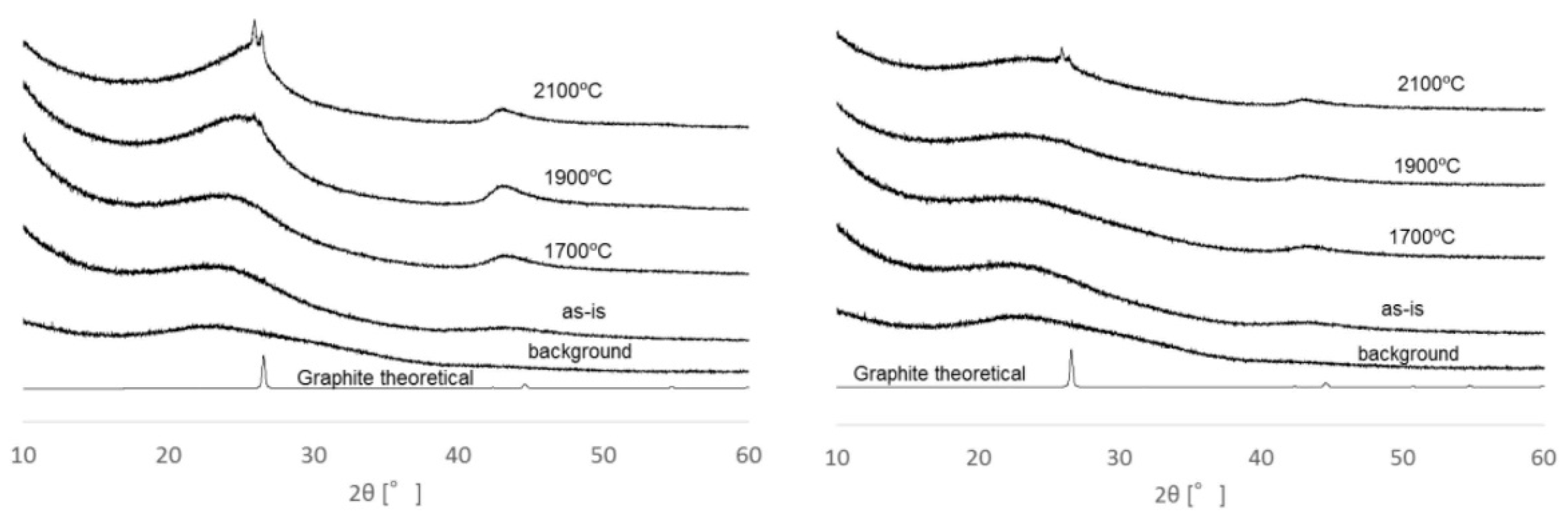
Figure 1 shows TEM images of as-is and heat-treated CNovel®. The heat-treated carbons exhibit clear graphene layers in peripheries. As shown in the X-ray diffraction (XRD) patterns of Figure 2, grafitication is confirmed by the sharp peaks around 27°.
Specific surface areas determined by nitrogen adsorption were tabulated in Table 1. All CNovels have surface areas of more than 1000 m2/g. Although heat- treatment up to @2100 °C causes small surface loss, they still hold much larger specific surface areas than those of Ketjen and Vulcan.
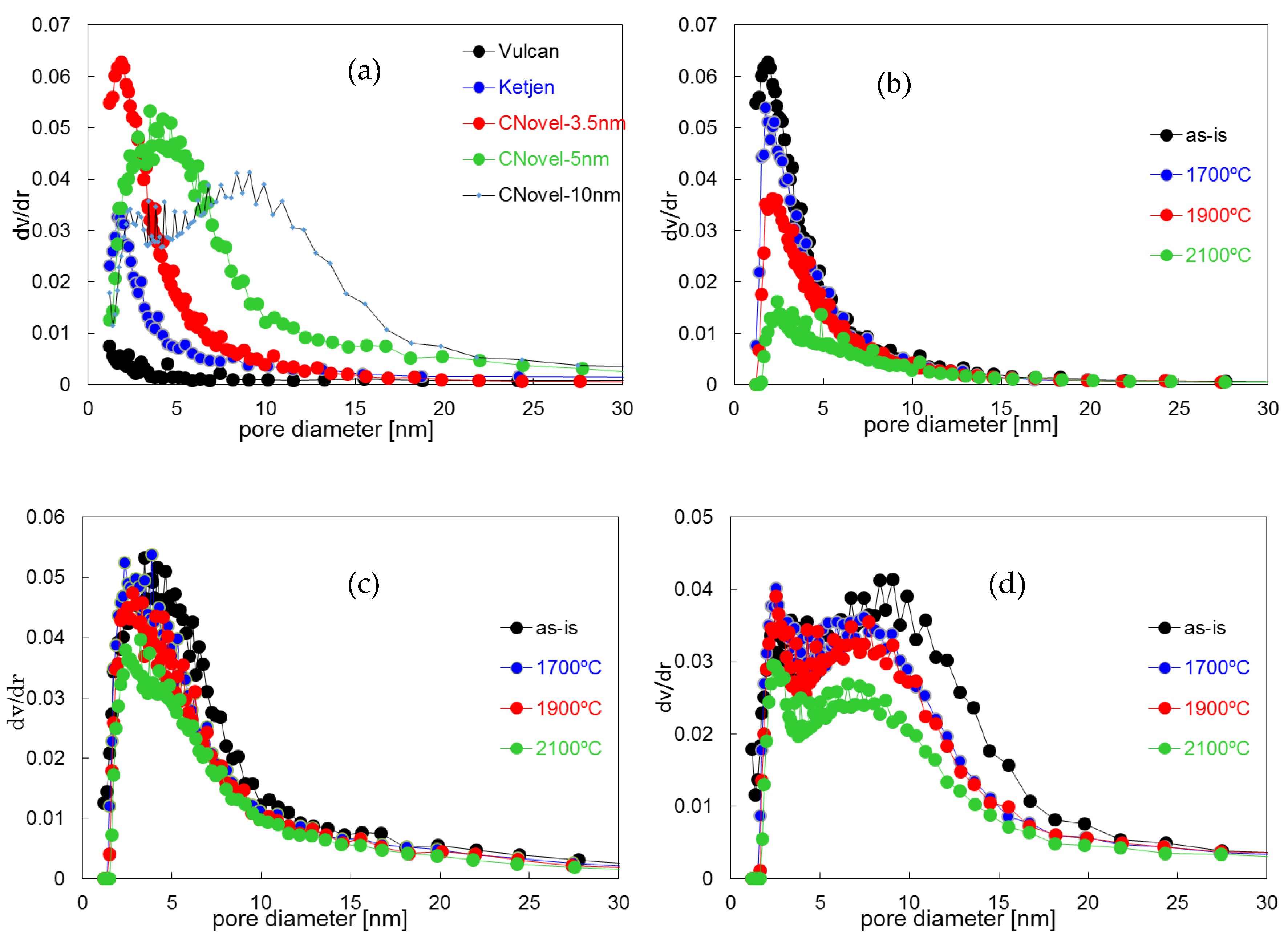
Pore size distributions, derived from the adsorption isotherms by the Dollimore-Heal (DH) method [27] are shown in Figure 3 for as-is CNovels 3.5, 5, and 10 nm, Ketjenblack® EC and Vulcan® XC-72. CNovels exhibit significantly larger pore volume in the mesopore region than the other two conventional carbon blacks. The effect of heat treatment on the pore-size distribution is shown in Figure 3. Although CNovels 5 and 10 nm did not exhibit significant change in pore volume and size-distribution, a considerable decrease in pore volume is seen for CNovels 3.5 nm.
2.1.2. Air Treatment
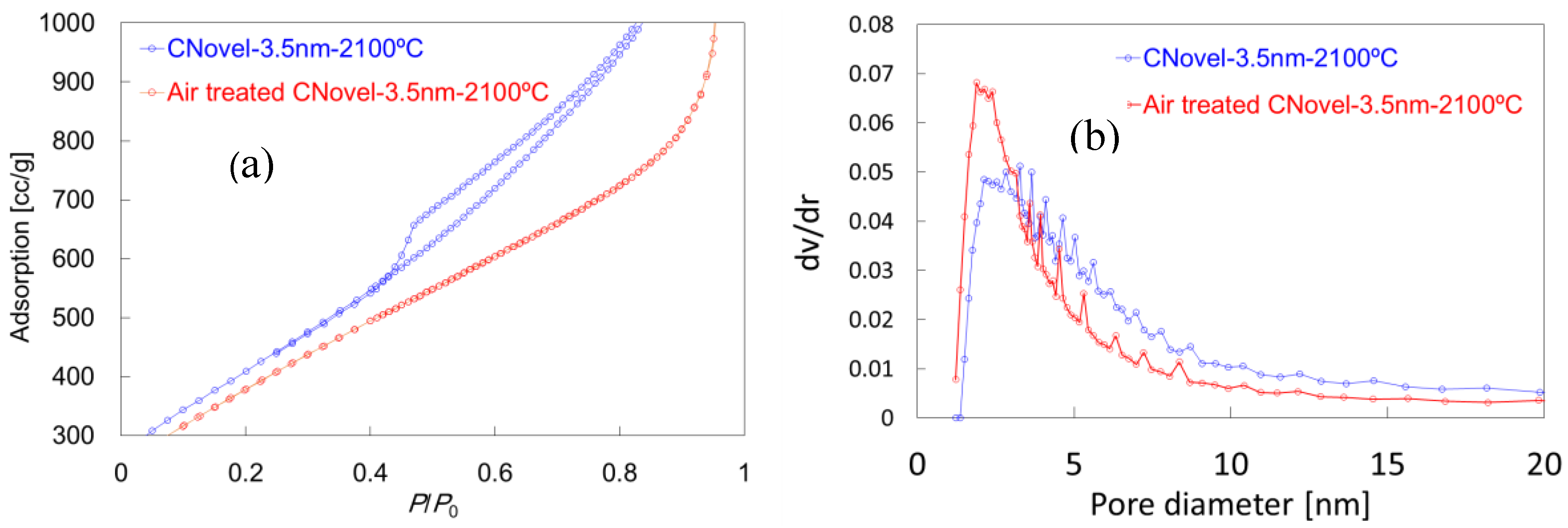
Specific surface areas of air treated samples are shown in Table 1 and their nitrogen isotherms and pore-size distributions are exhibited in Figure 4. Although the specific surface areas do not show significant decrease by oxidation up to 530 °C, a significant change was seen in the nitrogen isotherms. As shown in Figure 4a, while a large hysteresis is seen in the adsorption isotherm for the heat treated CNovels 3.5 nm, there is no hysteresis after air treatment. This change is not due to a pore-size distribution change as shown in Figure 4b but can be attributed to pore structure change from a rather closed-ended or bottlenecked structure to a more open-ended and through-pored structure [28].
2.1.3. Bead-Milling
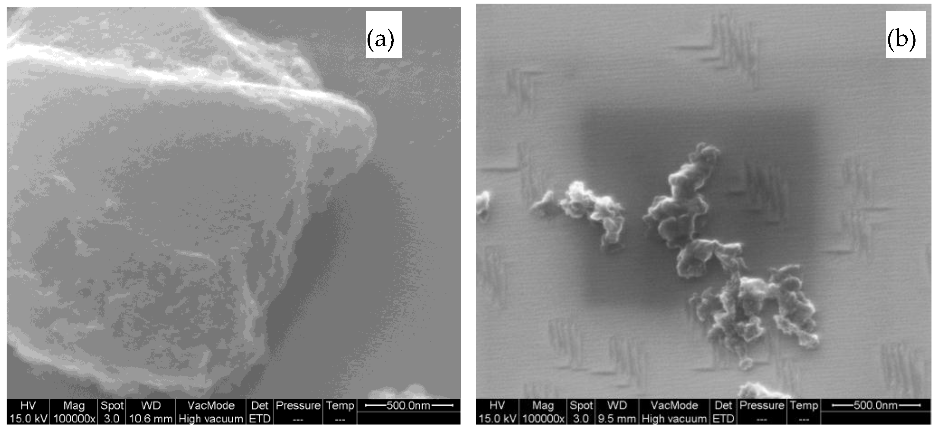
Scanning electron microscope (SEM) images of before and after bead-milling are shown Figure 5. Primary particles were successfully broken down into 10–100 nm region.
2.1.4. Functionalization
The density of acidic entities determined by the Boehm method is tabulated in Table 2. While the heat treatment removed all functionalities originally existed, both functionalization processes successfully introduced acidic functionalities. In fact, CNovels could not be dispersed in water after the heat treatment but could be easily dispersed after either treatment. The potassium manganite treatment, however, was found to hydrophilize the carbon too strongly to provide sufficient hydrophobicity for avoiding easy flooding at preliminary MEA tests and, therefore, the nitric acid treatment was used hereafter.
2.2. Pt/C
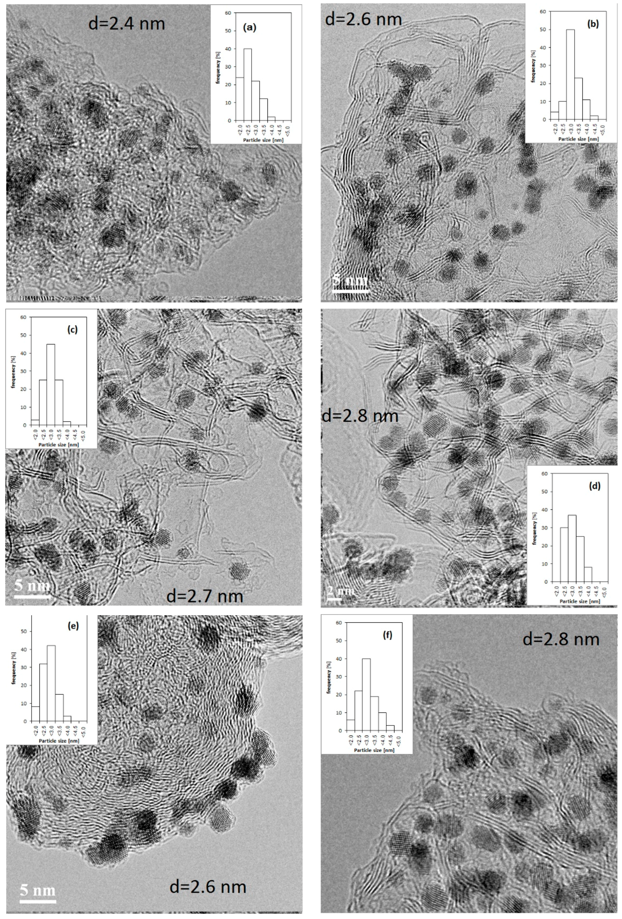
Figure 6 shows TEM images of the Pt deposited on CNovels 5 nm as-is, 3.5, 5 and 10 nm (2100 °C and nitric acid treated), 5 nm (2100 °C, nitric acid and air treated) and Vulcan® XC-72, and their particle size histograms. While Vulcan® shows Pt particles mainly on the peripheries, CNovels do not show such uneven distribution. These observations suggest that Pt particles exist only on the spherical surface of Vulcan® but CNovels have particles inside. Platinum particle sizes are 2.6–2.8 nm except for CNovel as-is which shows smaller particles.
2.3. Electrochemical Characteristics
2.3.1. RDE Measurement
Electrochemical surface area per unit weight of Pt (ECSA), ORR mass activity and specific activity determined by RDE measurement are summarized in Table 3 (average of three samples with standard error). ECSA were determined from CO stripping voltammetry and particle sizes were estimated assuming monodispersed spherical particles. The particle sizes estimated from TEM observation and ECSA measurement are significantly different for as-is CNovel. This was probably because smaller particles on the unstable carbon were detached or dissolved during the electrode preparation or conditioning process. Although other carbons support also showed disagreement with smaller degree, ORR activities were analyzed on the basis of measured ECSA. Mass and specific activities Pt/Vulcan are in the same ranges with the recent detailed study [16] for the same material and therefore, indicate the validity of the measurement in the present study. ORR activities of Pt/CNovels in RDE relative to Pt/Vulcan will be discussed later in this section in connection with those in MEA.
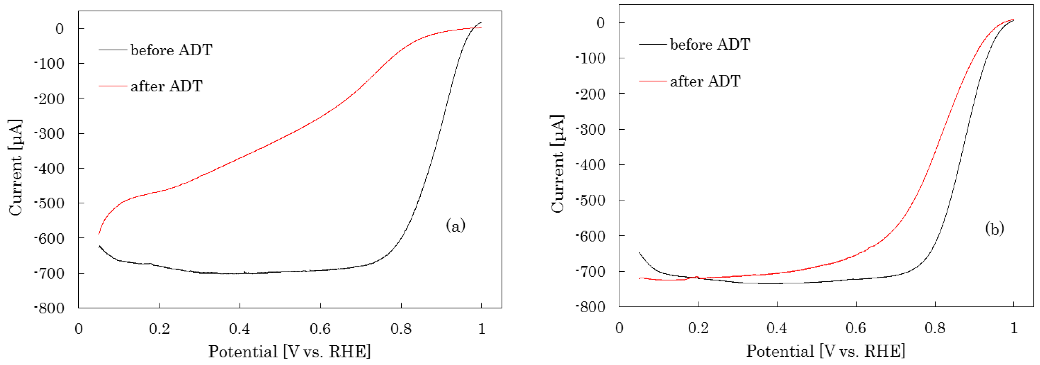
High potential accelerated durability test was applied in the RDE condition. Linear sweep voltammograms in O2 condition are shown in Figure 7 for as-is and heat-treated CNovels before and after the durability test. The as-is CNovel® catalyst exhibits significant change in the voltammograms and loss in ORR activities while heat-treated one shows only minor change. These contrasting results clearly demonstrate the effect of the high temperature gratification treatment as already shown other carbon materials.
2.3.2. MEA Test
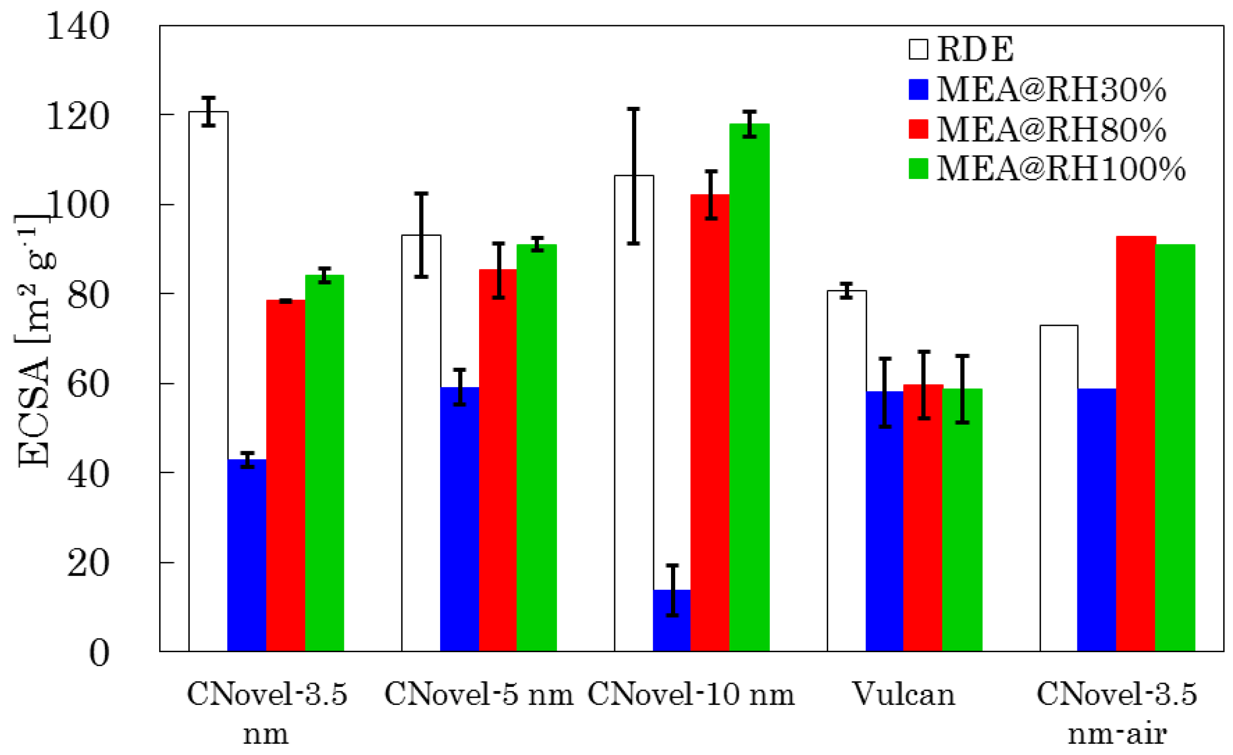
ECSAs determined by CO stripping are compared in Figure 8 (average of three samples with standard error) for MEAs with Pt/Vulcan and Pt/CNovels under different relative humidity conditions. ECSA on Pt/Vulcan exhibits no humidity-dependence of ECSA and this indicates that Pt particles on Vulcan® are all on the outside of solid carbon and covered with the ionomer to allow proton transfer even at relative humidity (RH) 30%. In contrast, Pt/CNovels shows lower ECSA under drier condition than wetter condition; this suggests Pt particles on inside pore surfaces of CNovels are not covered with the ionomer but can be reached by protons only under wet condition.
Sulfonic adsorptions are 10–14% as shown in Figure 9 (average of three samples with standard error). Higher sulfonic adsorption at 80% RH than at 100% RH is most likely due to smaller water absorption of the ionomer (more concentrated sulfonate) at 80% RH. Pt/Vulcan slightly showed higher coverages (12–14%) than Pt/CNovels (9–11%). Considering that fully Nafion-covered Pt(111) single crystal showed roughly 10% [6,10,13] sulfonate adsorption and that Pt/Vulcan is likely fully covered as well, The slightly lower sulfonate adsorptions of CNovels suggest that a considerable part of electrochemically available Pt surface is not covered by Nafion.
Current-Voltage (i-V) performances in a low current density region and specific activities (0.9 V) are also compared in Figure 10 and Figure 11 (average of three samples with standard error), respectively. Considering the difference in the activity measurement methods between RDE and MEA (RDE: anodic voltammetric sweep, MEA: cathodic galvanostatic sweep), comparison of absolute values is not valid, relative comparison of these values are still meaningful [4]. In the case of CNovels, the MEA activities of are generally higher than RDE activities except for CNovel-10 nm showing the roughly equal activity. In contrast, Pt/Vulcan showed a lower activity in MEA. This difference could be elucidated by the poisoning effect of the ionomer. Considering a significant part of Pt particles are not covered with the ionomer but are reachable by proton with water, these high activities of Pt/CNovels in MEA can be attributed to high activity of non-covered and non-poisoned Pt surface. Although a quantitative discussion on the ionomer poisoning effect is not possible, these significantly different trend in the activities results are not inexplicable considering the fact that fully covered Pt(111) with 10% sulfonic adsorption exhibited 80% activity loss [6,10,13].
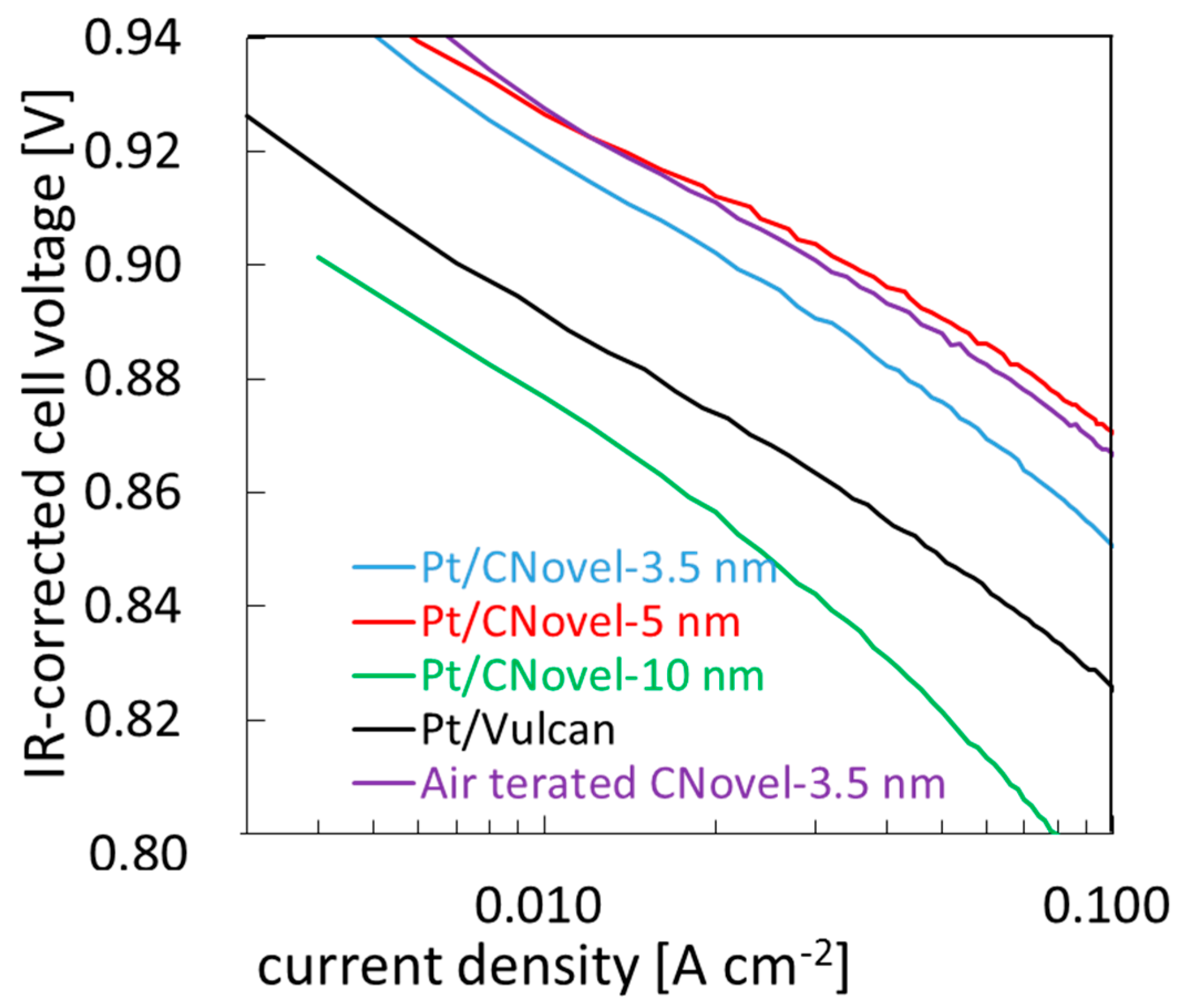
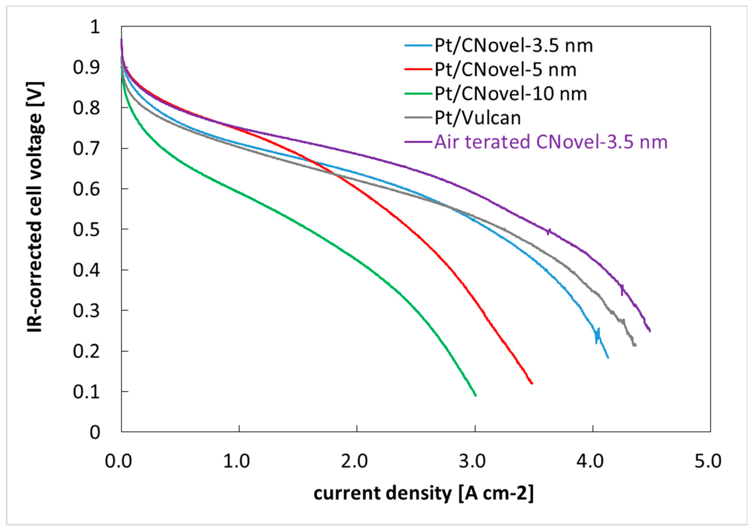
Overall i-V performances are shown in Figure 12. These i-V curves in the middle and large current density regions are significantly affected by protonic and oxygen transport resistances, both of which are controlled not only by the material properties but also by the composition such as ionomer/carbon weight ratio and preparation processes such as dispersion and application conditions. Therefore, it is not very meaningful to discuss the i-V performance in the middle and large current density regions s in detail on the basis of material properties. However, the i-V curve of Air-treated CNovel is significantly better than those of other carbons in the entire current density region. Therefore, the MEA electrode with Air-treated CNovel must have good protonic transport and good oxygen accessibility in addition to the high catalytic activity as shown in the previous section. The open-ended and through-pored pore structure obtained by the air treatment should provide a better gas path than dead-ended structure does. Ionomer non-coverage on Pt should have both positive and negative impacts on oxygen transport. As a positive side, what oxygen must permeate to the platinum surface is only a thin adsorbed water layer, instead of the ionomer phase, which form a dense layer on platinum [11]. As a negative side, even if protons can reach the bare platinum sites in a small current density during the cyclic voltammetry or CO stripping voltammetry, a large current density applied under the ORR condition may induce a huge ohmic loss that ends up with loss in the effective platinum surface area and increase in the oxygen transport resistance. Quantitative analysis of these complex effects, however, is so difficult that overall performance is the only indicator available to judge the electrodes.
In this context, other CNovel showing inferior performance to the air-treated one, are considered to have oxygen and/or proton transportation problems. These problems, however, are not well identified and not known to be solved by optimization of the MEA composition and processes.
3. Experimental
3.1. Sample Preparation
3.1.1. Materials
Three grades of mesoporous carbons, CNovel®, were purchased from Toyo Tanso Co., Ltd., (Osaka, Japan) whose nominal pore sizes are, 3.5, 5.0 and 10 nm. A Pt/Vulcan catalyst, TEC10V30E, was purchased from Tanaka Kikinzoku Kogyo (Tokyo, Japan) and used without further treatment, which is referred as Pt/Vulcan.
3.1.2. Heat Treatment for Gratification
Heat-treatment was carried out to graphitize the carbon under Ar atmosphere at 1700, 1900 and 2100 °C for 1 h.
3.1.3. Air Treatment
Graphitized carbons were subjected to low temperature (450–550 °C) heat treatment in air for 1 h to oxidize and remove fractional carbon pieces which may hinder the accessibility to inner pores.
3.1.4. Bead Milling
The agglomerate (secondary) particle size of CNovel® is 2–10 µm, which is too large for forming a thin uniformly-distributed film for the RDE and MEA experiments. To reduce the size, bead-milling was carried out under the condition shown in Table 4.
3.1.5. Functionalization
The heat-treated CNovel® was found difficult to uniformly deposit small platinum particles on it. Therefore, surface functionalization was carried out by dispersing the carbon in heated (80 °C) nitric acid (1 M) or ambient-temperature potassium manganite (VII) (0.02 M) in sulfuric acid (3 M) for 1 h before thoroughly rinsed with pure water.
3.1.6. Platinum Deposition
Platinum deposition was carried out by a method described in detail elsewhere [29]. In short, commercially available hexahydroxyplatinate (IV) acid (ethanolamine solution (8.8%)) (Tanaka Kikinzoku Kogyo, 0.9233 g) was mixed with water (100 mL) and carbon (0.1 g), then, heated and chemically reduced by adding formic acid (Wako Pure Chemical Co., Osaka, Japan, 16 mL) when the mixture was heated up to 50 °C and agitating the mixture for 1 h while the temperature was maintained at 90 °C. The platinum loading was controlled to be 30 wt. % (Pt/(Pt + C)).
3.1.7. Rotating Disk Electrode (RDE) Thin Film Preparation
Pt/C was dispersed in ethanol/water (8/2 v/v) and placed on glassy carbon rod (0.246 cm2) without ionomers before drying at 100 °C for 1 h to form Pt/C thin film of 8 gPt/cm2.
3.1.8. Membrane Electrode Assembly (MEA) Preparation
A platinum-deposited carbon, an ionomer solution (Nafion® D2020, DuPont) and solvent (ethanol/water 1/1 w/w) were mixed and agitated by ultrasonic vibration. The ionomer/carbon weight ratio was 1.0. This ink was applied on a PTFE sheet by a doctor blade process and dried to form a catalyst sheet of 0.13 mgPt/cm2 platinum loading. This catalyst sheet (1 cm2) was transferred to a Nafion® membrane (NR-211) by a decal method with hot-pressing (50 kg/cm2, 120 °C, 5 min). An anode catalyst layer was formed similarly using Pt/Vulcan with 0.15 mgPt/cm2 and ionomer/carbon weight ratio of 1.0 to form an MEA. A single cell was assembled with the MEA, carbon papers (TGP-H-030) with microporous layers, and graphitic carbon current collectors with straight channel (0.4 mm-width channels and lands) flow field.
3.2. Characterization
3.2.1. Carbon
Carbons were characterized by XRD (Ultima, Rigaku, Tokyo, Japan), nitrogen sorption measurement (Autosorb-1, Quantachrome, Boynton Beach, FL, USA), SEM (Quanta 200, FEI, Hillsboro, OR, USA) and TEM (JEM-2100F, JEOL, Akishima, Japan). Their surface functionality was also analyzed by the Boehm method [30].
3.2.2. Pt/C
Pt/C was characterized by XRD (Ultima, Rigaku, Akishima, Japan) and TEM (JEM-2100F, JEOL).
3.2.3. Electrochemical Characterization by RDE
Electrochemical Characterization and ORR activity measurement were carried out using a three-electrode configuration with the thin film RDE, a Pt mesh and RHE as the working, counter and reference electrodes, respectively using a potentiostat/galvanostat (HA-151B, Hokuto Denko, Tokyo, Japan). The electrolyte was 0.1 M HClO4 (ultrapur, Kanto Chemical, Tokyo, Japan). Electrochemical procedures before and during the measurement is summarized in Table 5. ORR activity was determined by the difference between the ORR current and background current (both at 0.9 V on anodic sweep). Accelerated durability test protocol is in Table 6.
3.2.4. MEA Performance Test & Sulfonic Coverage Measurement
A series of break-in procedures shown Table 7 were conducted for the MEA using a potentiostat/galvanostat (Model 2100, Toho Technical Research Co., Yokohama, Japan). Then MEA performance test was conducted galvanostatically at 55, 60 and 82 °C with the same current-sweep condition with the break-in procedure. High frequency resistance was measured simultaneously with an AC resistance meter (FC-100R, Chino Co., Tokyo, Japan) at 10 kHz and used for IR correction. ECSA and sulfonic coverage were evaluated by CO stripping method and CO displacement method developed by Furuya et al. [31], respectively with a condition shown in Table 8. ECSA and sulfonate coverage were respectively determined as following two equations:
ECSA (cm2Pt) = CO stripping Charge (C)/512(C cm−2Pt)
Sulfonate coverage = 2 × reduction charge at 0.4 V holding (C)/CO stripping Charge (C).
4. Conclusions
An MgO-templated mesoporous carbon, CNovel®, was employed as a catalyst support for the cathode of PEFCs after modifying its dimensional, crystalline, surface and porous structures. Although the catalytic activity of Pt on CNovel® was comparable with that on a non-porous carbon, Vulcan®, in the RDE configuration, Pt/CNovel showed a considerably higher activity than Pt/Vulcan in the MEA condition. This difference is probably because Pt on inside pores of CNovel® is not covered nor poisoned with Nafion® ionomer while protons can still reach that Pt with the help of water. Superior MEA performance in the middle and high current-density regions was also obtained by an MEA using Pt/CNovel with air treatment which made the pore structure open-ended and through-pored. This study successfully demonstrated that utilizing mesopore is another strategy to achieve a superior performance for MEA development.
Author Contributions
Y.K. planed and performed the experiments and wrote the paper; T.T. performed the sulfonate adsorption analysis; Y.M. supervised the plan, experiment and writing.
Conflicts of Interest
The authors declare no conflict of interests.
References
- Lu, Y.; Du, S.; Steinberger-Wilckens, R. Temperature-controlled growth of single-crystal Pt nanowire arrays for high performance catalyst electrodes in polymer electrolyte fuel cells. Appl. Catal. B Environ. 2015, 164, 389–395. [Google Scholar] [CrossRef]
- Lu, Y.; Du, S.; Steinberger-Wilckens, R. Three-dimensional catalyst electrodes based on PtPd nanodendrites for oxygen reduction reaction in PEFC applications. Appl. Catal. B Environ. 2016, 187, 108–114. [Google Scholar] [CrossRef]
- Du, S.; Millington, B.; Pollet, B.G. The effect of Nafion ionomer loading coated on gas diffusion electrodes with in-situ grown Pt nanowires and their durability in proton exchange membrane fuel cells. Int. J. Hydrog. Energy 2011, 36, 4386–4393. [Google Scholar] [CrossRef]
- Gasteiger, H.A.; Kocha, S.S.; Sompalli, B.; Wagner, F.T. Activity benchmarks and requirements for Pt, Pt-alloy, and non-Pt oxygen reduction catalysts for PEMFCs. Appl. Catal. B Environ. 2005, 56, 9–35. [Google Scholar] [CrossRef]
- Debe, M.K. Novel catalysts, catalysts support and catalysts coated membrane methods. In Handbook of Fuel Cells; Wiley: Hoboken, NJ, USA, 2010. [Google Scholar]
- Subbaraman, R.; Strmcnik, D.; Paulikas, A.P.; Stamenkovic, V.R.; Markovic, N.M. Oxygen Reduction Reaction at Three-Phase Interfaces. ChemPhysChem 2010, 11, 2825–2833. [Google Scholar] [CrossRef] [PubMed]
- Suzuki, T.; Kudo, K.; Morimoto, Y. Model for investigation of oxygen transport limitation in a polymer electrolyte fuel cell. J. Power Sources 2013, 222, 379–389. [Google Scholar] [CrossRef]
- Mashio, T.; Ohma, A.; Yamamoto, S.; Shinohara, K. Analysis of Reactant Gas Transport in a Catalyst Layer. ECS Trans. 2007, 11, 529–540. [Google Scholar]
- Kodama, K.; Jinnouchi, R.; Suzuki, T.; Murata, H.; Hatanaka, T.; Morimoto, Y. Increase in adsorptivity of sulfonate anions on Pt (111) surface with drying of ionomer. Electrochem. Commun. 2013, 36, 26–28. [Google Scholar] [CrossRef]
- Subbaraman, R.; Strmcnik, D.; Stamenkovic, V.; Markovic, N.M. Three Phase Interfaces at Electrified Metal−Solid Electrolyte Systems 1. Study of the Pt(hkl)−Nafion Interface. J. Phys. Chem. C 2010, 114, 8414–8422. [Google Scholar] [CrossRef]
- Jinnouchi, R.; Kudo, K.; Kitano, N.; Morimoto, Y. Molecular Dynamics Simulations on O2 Permeation through Nafion Ionomer on Platinum Surface. Electrochim. Acta 2016, 188, 767–776. [Google Scholar] [CrossRef]
- Kudo, K.; Jinnouchi, R.; Morimoto, Y. Humidity and Temperature Dependences of Oxygen Transport Resistance of Nafion Thin Film on Platinum Electrode. Electrochim. Acta 2016, 209, 682–690. [Google Scholar] [CrossRef]
- Kodama, K.; Shinohara, A.; Hasegawa, N.; Shinozaki, K.; Jinnouchi, R.; Suzuki, T.; Hatanaka, T.; Morimoto, Y. Catalyst Poisoning Property of Sulfonimide Acid Ionomer on Pt (111) Surface. J. Electrochem. Soc. 2014, 161, F649–F652. [Google Scholar] [CrossRef]
- Ito, T.; Matsuwaki, U.; Otsuka, Y.; Hatta, M.; Hayakawa, K.; Matsutani, K.; Tada, T.; Jinnai, H. Three-Dimensional Spatial Distributions of Pt Catalyst Nanoparticles on Carbon Substrates in Polymer Electrolyte Fuel Cells. Electrochemistry 2011, 79, 374–376. [Google Scholar] [CrossRef] [Green Version]
- Shinozaki, K.; Yamada, H.; Morimoto, Y. Relative Humidity Dependence of Pt Utilization in Polymer Electrolyte Fuel Cell Electrodes: Effects of Electrode Thickness, Ionomer-to-Carbon Ratio, Ionomer Equivalent Weight, and Carbon Support. J. Electrochem. Soc. 2011, 158, B467–B475. [Google Scholar] [CrossRef]
- Shinozaki, K.; Morimoto, Y.; Pivovar, B.S.; Kocha, S.S. Suppression of oxygen reduction reaction activity on Pt-based electrocatalysts from ionomer incorporation. J. Power Sources 2016, 325, 745–751. [Google Scholar] [CrossRef] [Green Version]
- Iden, H.; Mashio, T.; Ohma, A. Gas transport inside and outside carbon supports of catalyst layers for PEM fuel cells. J. Electroanal. Chem. 2013, 708, 87–94. [Google Scholar] [CrossRef]
- Iden, H.; Ohma, A. An in situ technique for analyzing ionomer coverage in catalyst layers. J. Electroanal. Chem. 2013, 693, 34–41. [Google Scholar] [CrossRef]
- Chan, K.; Eikerling, M. A Pore-Scale Model of Oxygen Reduction in Ionomer-Free Catalyst Layers of PEFCs. J. Electrochem. Soc. 2011, 158, B18–B28. [Google Scholar] [CrossRef]
- Ding, J.; Chan, K.-Y.; Ren, J.; Xiao, F.-S. Platinum and platinum–ruthenium nanoparticles supported on ordered mesoporous carbon and their electrocatalytic performance for fuel cell reactions. Electrochim. Acta 2005, 50, 3131–3141. [Google Scholar] [CrossRef]
- Joo, S.H.; Pak, C.; You, D.J.; Lee, S.-A.; Lee, H.I.; Kim, J.M.; Chang, H.; Seung, D. Ordered mesoporous carbons (OMC) as supports of electrocatalysts for direct methanol fuel cells (DMFC): Effect of carbon precursors of OMC on DMFC performances. Electrochim. Acta 2006, 52, 1618–1626. [Google Scholar] [CrossRef]
- Salgado, J.R.C.; Quintana, J.J.; Calvillo, L.; Lazaro, M.J.; Cabot, P.L.; Esparbe, I.; Pastor, E. Carbon monoxide and methanol oxidation at platinum catalysts supported on ordered mesoporous carbon: The influence of functionalization of the support. Phys. Chem. Chem. Phys. 2008, 10, 6796–6806. [Google Scholar] [CrossRef] [PubMed]
- Song, S.; Liang, Y.; Li, Z.; Wang, Y.; Fu, R.; Wu, D.; Tsiakaras, P. Effect of pore morphology of mesoporous carbons on the electrocatalytic activity of Pt nanoparticles for fuel cell reactions. Appl. Catal. B Environ. 2010, 98, 132–137. [Google Scholar] [CrossRef]
- Hori, M.; Kato, H.; Matsumoto, S.; Nishi, N. FC Catalyst with Mesoporous Carbon. Meet. Abstr. 2013, MA2013-02, 1500. Available online: https://ecs.confex.com/ecs/224/webprogram/Paper22769.html (accessed on 31 May 2018).
- Toyo Tanso New Developed Product Porous Carbon (CNovel®). Available online: http://www.toyotanso.com/Products/new_developed_products/cnovel.html (accessed on 28 January 2018).
- Toyo Tanso Carbon Products. Available online: http://www.toyotanso.co.jp/Products/faq/cnovel/1701.cnv1.html (accessed on 20 May 2018). (In Japanese).
- Dollimore, D.; Heal, G.R. Pore-size distribution in typical adsorbent systems. J. Colloid Interface Sci. 1970, 33, 508–519. [Google Scholar] [CrossRef]
- Gregg, S.J.; Sing, K.S.W.; Salzberg, H.W.K. Adsorption, Surface Area, and Porosity; Academic Press: London, UK; New York, NY, USA, 1982. [Google Scholar]
- Sugita, Y.; Ito, K. Platinum Black Powder, Platinum Black Colloid, Method for Producing Platinum Black Powder, and Method for Producing Platinum Black Colloid. WO2010082443A1, 22 July 2010. [Google Scholar]
- Boehm, H.P. Some aspects of the surface chemistry of carbon blacks and other carbons. Carbon 1994, 32, 759–769. [Google Scholar] [CrossRef]
- Furuya, Y.; Mashio, T.; Ohama, A.; Shinohara, K. Evaluation of Anion Adsorption on Pt Surface in MEA. Meet. Abstr. 2012, MA2012-02, 1272. Available online: http://ma.ecsdl.org/content/MA2012-02/13/1272.full.pdf (accessed on 31 May 2018).
Figure 1.
TEM images of CNovel. (a) 3.5 nm as-is; (b) 3.5 nm after 2100 °C heat treatment; (c) 10 nm as-is; (d) 10 nm after 2100 °C heat treatment.
Figure 1.
TEM images of CNovel. (a) 3.5 nm as-is; (b) 3.5 nm after 2100 °C heat treatment; (c) 10 nm as-is; (d) 10 nm after 2100 °C heat treatment.

Figure 2.
XRD patterns of as-is and heat-treated CNovel®; Left: 3.5 nm, Right: 10 nm.

Figure 3.
Pore size distributions: (a) Ketjen, Vulcan and CNovel® 3.5 nm, 5 nm and 10 nm; (b–d) heat treated CNovel® (b) 3.5 nm; (c) 5 nm and (d) 10 nm.
Figure 3.
Pore size distributions: (a) Ketjen, Vulcan and CNovel® 3.5 nm, 5 nm and 10 nm; (b–d) heat treated CNovel® (b) 3.5 nm; (c) 5 nm and (d) 10 nm.

Figure 4.
(a) N2 sorption isotherms and (b) pore size distributions after heat treatment in air at 530 °C.
Figure 4.
(a) N2 sorption isotherms and (b) pore size distributions after heat treatment in air at 530 °C.

Figure 5.
SEM images of CNovel 5 nm (a) before and (b) after bead-milling.

Figure 6.
TEM Images of Pt/Cs and Pt particle size distribution with average particle sizes, (a) CNovels 5 nm as-is (b) CNovels 3.5; (c) 5 and (d) 10 nm (2100 °C and nitric acid treated); (e) Vulcan XC-72 and (f) CNovels 3.5 nm (2100 °C, nitric acid and air treated).
Figure 6.
TEM Images of Pt/Cs and Pt particle size distribution with average particle sizes, (a) CNovels 5 nm as-is (b) CNovels 3.5; (c) 5 and (d) 10 nm (2100 °C and nitric acid treated); (e) Vulcan XC-72 and (f) CNovels 3.5 nm (2100 °C, nitric acid and air treated).

Figure 7.
Linear sweep voltammograms for ORR (Oxygen Reduction Reaction) activity measurement before and after accelerated durability test of (a) as-is and (b) heat-treated CNovels 5 nm.
Figure 7.
Linear sweep voltammograms for ORR (Oxygen Reduction Reaction) activity measurement before and after accelerated durability test of (a) as-is and (b) heat-treated CNovels 5 nm.

Figure 8.
ECSAs of Pt on CNovels and Vulcan of MEA under various RH and RDE conditions, determined by CO stripping voltammetry.
Figure 8.
ECSAs of Pt on CNovels and Vulcan of MEA under various RH and RDE conditions, determined by CO stripping voltammetry.

Figure 9.
Sulfonate adsorption on Pt on CNovels and Vulcan of MEA.

Figure 10.
i-V performance of MEAs on a low current density region.

Figure 11.
Specific ORR activities of Pt on CNovels and Vulcan of membrane electrode assembly (MEA) at 80% RH and RDE.
Figure 11.
Specific ORR activities of Pt on CNovels and Vulcan of membrane electrode assembly (MEA) at 80% RH and RDE.

Figure 12.
IR-corrected voltage/current density relation by MEA tests at RH80%.


Table 1.
Specific surface areas of carbons after bead-milling.
| Sample | Specific Surface Area [m2/g] |
|---|---|
| Ketjen black | 800 |
| Vulcan XC | 250 |
| CNovel 3.5 nm as-is | 1270 |
| CNovel 5 nm as-is | 1550 |
| CNovel 10 nm as-is | 1630 |
| CNovel 5 nm @1700 °C | 1550 |
| CNovel 5 nm @1900 °C | 1490 |
| CNovel 5 nm @2100 °C | 1270 |
| CNovel 5 nm @2100 °C Air treated@500 °C | 1380 |
| CNovel 5 nm @2100 °C Air treated@530 °C | 1280 |
| CNovel 5 nm @2100 °C Air treated@540 °C | 890 |
| CNovel 5 nm @2100 °C Air treated@550 °C | 540 |
Table 2.
Acidic entity density of as-is and heat and acid treated CNovel.
| Sample | Acidic Entity Density [mmol/g] |
|---|---|
| CNovel 5 nm as-is | 0.34 |
| 2100 °C treated | Not detected |
| KMnO4 treated | 2.0 |
| HNO3 treated | 0.073 |
Table 3.
Electrochemical properties of Pt/C by RDE (Rotating Disk Electrode) measurement.
| Catalyst | ECSA | Particle Size [m] | Mass Activity | Specific Activity | |
|---|---|---|---|---|---|
| [m2/gPt] | TEM | ECSA * | [A/gPt] | [μA/cmPt2] | |
| Pt/Vulcan | 80 ± 1 | 2.6 | 3.5 ± 0.1 | 550 ± 20 | 690 ± 30 |
| Pt/CNovel-3.5 nmHT | 121 ± 3 | 2.6 | 2.3 ± 0.1 | 680 ± 70 | 560 ± 60 |
| Pt/CNovel-5 nmHT | 93 ± 9 | 2.7 | 3.0 ± 0.3 | 410 ± 40 | 440 ± 60 |
| Pt/CNovel-5 nmAsIs | 74 ± 2 | 2.4 | 3.8 ± 0.1 | 250 ± 40 | 340 ± 60 |
| Pt/CNovel-10 nmHT | 110 ± 15 | 2.8 | 2.5 ± 0.3 | 620 ± 80 | 600 ± 100 |
* Particle size estimated from ECSA (Electrochemical surface area) was obtained by assuming monodispersed spherical particles with Pt utilization of 100%; D(nm) = 6000/{ECSA(m2/g) * (g/cm3)}.
Table 4.
Bead-milling condition.
| Condition | Detail |
|---|---|
| Apparatus | Micro media MMPC-X1, Bühler |
| Dispersion medium | 50 wt. % EtOH in water |
| Concentration | 12 g/L |
| Dispersion Volume | 1 L |
| Bead | YSZ (0.3 mm in diameter) |
| Bead volume (Volume%) | 90vol% |
| Rotor and Stator material | SiC |
| Rotor speed | 10 m/s * |
| Temperature | 18–27 °C |
| Duration | 60 min |
* As rotor speed, circumferential speed was employed, which is calculated by multiplying RPM/60, rotor diameter and pi.
Table 5.
RDE test procedures.
| Step | Condition |
|---|---|
| 1 Electrolyte deaeration | Ar bubbling for 30 min at 30 °C |
| 2 Electrode cleaning | Potential cycles: 0.05–1.2 V, 500 mV/s, 50 cycles |
| 3 Electrochemical surface area (ECSA) evaluation | Cyclic voltammetry: 0.05–1.0 V, 100 mV/s, 5 cycles |
| 4 Gas exchange | O2 bubbling for 30 min. |
| 5 ORR current measurement | Cyclic voltammetry: 0.05–1.0 V, 10 mV/s, 400 rpm * |
| 6 Reevaluation of ECSA | Repeat Step 1–3 |
| 7 Background evaluation | Linear sweep voltammetry: 0.05–1.0 V, 10 mV/s, 400 rpm |
* 400 rpm was selected to avoid detachment of catalyst particles off the glassy carbon, which occurs at a higher rotation rate for a thin catalyst film without an ionomer as a binder.
Table 6.
Accelerated durability test procedure.
| Step | Condition |
|---|---|
| 1 ORR activity measurement | procedures shown Table 5 |
| 2 Set the water bath temperature | 60 °C |
| 3 Potential cycles | between: 1.0–1.5 V, 100 mV/s, 10,000 cycles |
| 4 ORR activity measurement | procedures shown Table 5 at 30 °C |
Table 7.
MEA break- in protocol.
| Step | Condition |
|---|---|
| 1. Voltage cycles | 0.115–1.2 V, 50 mV/s, 25 cycles, |
| Cell Temperature: 55 °C | |
| Cathode gas: N2 1 L/min, RH 100% | |
| Anode gas: (H2:N2 1:9 v/v) 1 L/min, RH 100% | |
| 2. Current sweeps | 0 A (Open circuit) to 5A or to 0.1 V, 10 mA/s, step back to open circuit, 5 sweeps |
| Cell Temperature: 55 °C | |
| Cathode gas: Air 2 L/min at RH 100%, 40 kPag | |
| Anode gas: H2 0.5 L/min RH 100%, 40 kPag |
Table 8.
ECSA and Sulfonic coverage determination.
| Step | Condition |
|---|---|
| 1. Presetting | Cell Temperature: 55, 60, 82 °C (=RH100, 80, 30%) Cathode gas: N2 1 L/min Anode gas: (H2:N2 1:9 v/v) 1 L/min |
| 2. Cleaning: Potential cycle | 0.115–1.0 V at 20 mV/s, 3 cycles |
| 3. Potential Holding | 0.015 V (CO adsorption) for 20 min 0.4 V (for sulfonate coverage) for 20 min |
| 4. Cathode gas switch | 5% CO in N2 0.4 L/min |
| 5. CO stripping potential sweep | 0.4–1.0 V 20 mV/s |
© 2018 by the authors. Licensee MDPI, Basel, Switzerland. This article is an open access article distributed under the terms and conditions of the Creative Commons Attribution (CC BY) license (http://creativecommons.org/licenses/by/4.0/).
Share and Cite
MDPI and ACS Style
Kamitaka, Y.; Takeshita, T.; Morimoto, Y. MgO-Templated Mesoporous Carbon as a Catalyst Support for Polymer Electrolyte Fuel Cells. Catalysts 2018, 8, 230. https://doi.org/10.3390/catal8060230
AMA Style
Kamitaka Y, Takeshita T, Morimoto Y. MgO-Templated Mesoporous Carbon as a Catalyst Support for Polymer Electrolyte Fuel Cells. Catalysts. 2018; 8(6):230. https://doi.org/10.3390/catal8060230
Chicago/Turabian StyleKamitaka, Yuji, Tomohiro Takeshita, and Yu Morimoto. 2018. "MgO-Templated Mesoporous Carbon as a Catalyst Support for Polymer Electrolyte Fuel Cells" Catalysts 8, no. 6: 230. https://doi.org/10.3390/catal8060230
Note that from the first issue of 2016, this journal uses article numbers instead of page numbers. See further details here.