New Layered Oxide-Fluoride Perovskites: KNaNbOF5 and KNaMO2F4 (M = Mo6+, W6+)


Abstract
: KNaNbOF5 and KNaMO2F4 (M = Mo6+, W6+), three new layered oxide-fluoride perovskites with the general formula ABB′X6, form from the combination of a second-order Jahn-Teller d0 transition metal and an alkali metal (Na+) on the B-site. Alternating layers of cation vacancies and K+ cations on the A-site complete the structure. The K+ cations are found in the A-site layer where the fluoride ions are located. The A-site is vacant in the adjacent A-site layer where the axial oxides are located. This unusual layered arrangement of unoccupied A-sites and under bonded oxygen has not been observed previously although many perovskite-related structures are known.1. Introduction
Perovskites with the general formula ABX3 are some of the most studied structures owing to their many interesting properties including magnetism, ionic conductivity, and ferroelectricity [1-3]. Their structure and properties can be altered by substitution at either the A- or B-sites or creating either cation or anion vacancies. For example, ferromagnetism has been achieved with the complex perovskite AA′3B4O12, such as CaCu3Ge4O12 [1], and ionic conductivity has been observed for the A-site deficient perovskites Li3xLa(2/3)-x □ 1/3-2xTiO3 (0 < x < 0.16) [2].
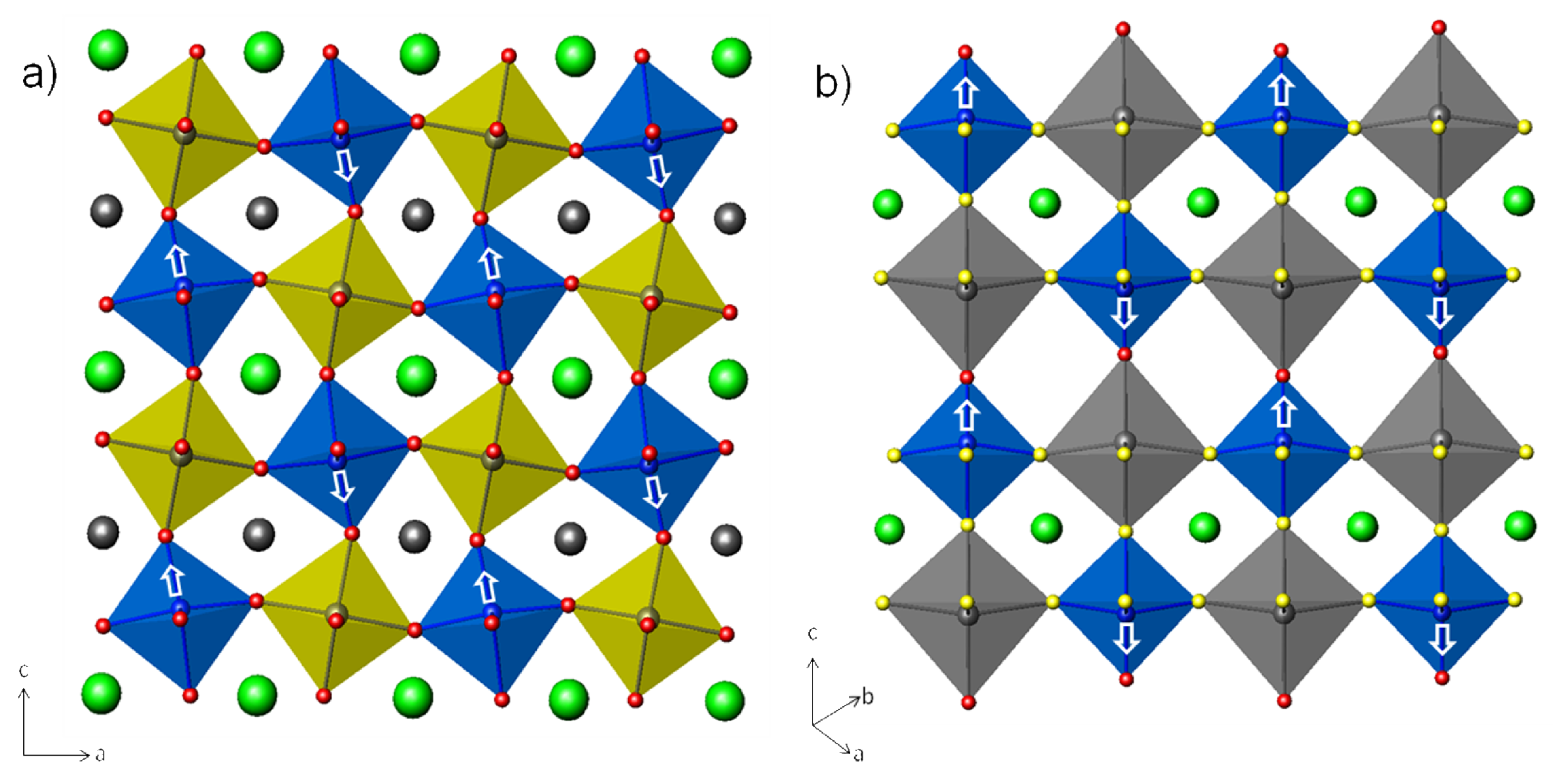
A-site cation ordering is typically seen in anion deficient perovskites, such as the antiferromagnetic YBaFe2O5 where the A-site cations (Y3+ and Ba2+ ) are ordered owing to the oxygen vacancies (Figure 1a) [4]. Ordered layers of occupied and unoccupied A-sites occur in non-stoichiometric perovskites A1-xBO3 [5-8]. For example, La1/3NbO3 contains a ReO3 framework of NbO6 octahedra with unoccupied A-site layers and A-site layers occupied with 2/3 La alternating along c (Figure 1b) [6,7] Examples of A-site cation ordering in stoichiometric AA′B2X6 and AA′BB′X6 perovskites with neither anion vacancies nor A-site vacancies are rare [9]. Woodward et al. showed that in NaLnMnWO6 (Ln = Ce, Pr, Sm, Gd, Dy and Ho) and NaLnMgWO6 (Ln = Ce, Pr, Sm, Gd, Tb, Dy and Ho) the A-site cations Na and Ln prefer to order in a layered arrangement [10,11]. The layered A-site ordering is stabilized by the second order Jahn Teller displacement of the d0 transition metal W at the B-site towards the oxide that is under bonded to alleviate the lattice strain arising from the A-site cations size mismatch (Figure 1c).
In comparison, B-site cation ordering in A2BB′X6 double perovskites has been well documented [12-14]. The majority of the B and B′ cations crystallize in an ordered rock-salt structure. In general, a disordered arrangement is observed when the oxidation states of B and B′ differ by less than two, whereas a difference greater than two nearly always produces an ordered arrangement [12]. When the difference in oxidation state is exactly two, disordered, partially ordered or fully ordered arrangements can result, depending on the differences in size and/or bonding preference of the B and B′ cations [12,15,16].
Oxyfluoride perovskites that contain ordered oxide and fluoride ions with the general formula [MOxF6-x]n- (x = 1, n = 2, and M = V5+, Nb5+, Ta5+; x = 2, n = 2, and M = Mo6+, W6+; x = 2, n = 3, and M = V5+, Nb5+, Ta5+; x = 3, n = 3, and M = Mo6+) are known but not common [17]. One well known example Na3MoO3F3, which crystallizes in the cryolite structure and has ordered oxide and fluoride ligands, displays ferroelectric-ferroelastic properties [3]. In this paper, we report a new class of A-site deficient oxyfluoride perovskites ABMOxF6-x (where A = K+; B = Na+; x =1, M= Nb5+; x = 2, M= Mo6+, W6+) that crystallize with both A- and B-site ordered cations. KNaNbOF5 [18] and KNaMO2F4 (M = Mo6+, W6+) have a rock-salt ordering of the B-site Na and Nb/M cations. The A-sites are arranged in a layered manner where one A-site layer contains all of the K+ cations and in the adjacent layer the A-sites are completely vacant.
2. Results and Discussion
2.1. Structure description
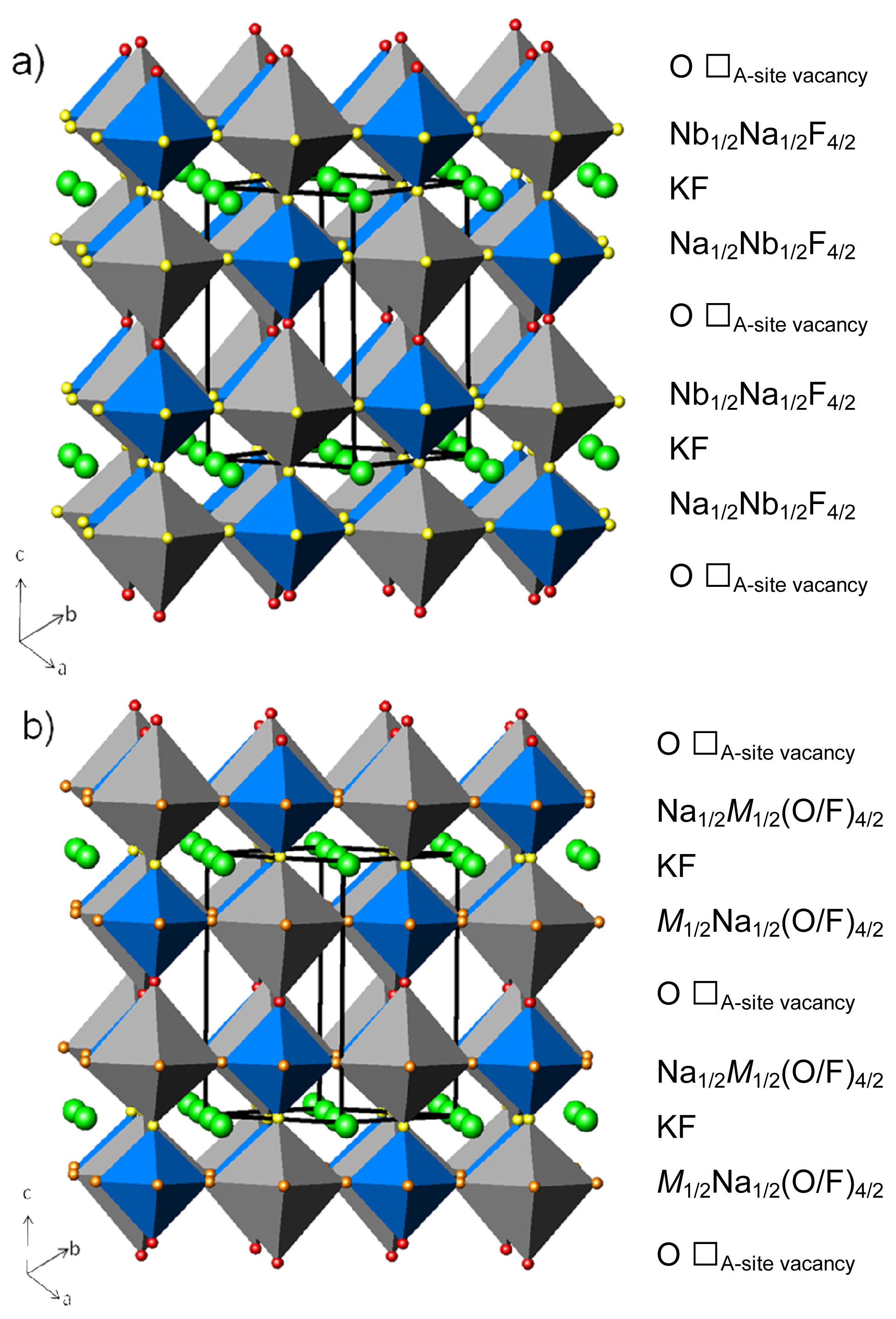
The polyhedral representations of KNaNbOF5 and KNaMO2F4 (M = Mo6+, W6+) are shown in Figure 2. These three-dimensional structures can be described as an ordered rock-salt double perovskite with the general formula ABB′X6 with ordered A-site layers where K+ occupies half the A-sites and Na+ and Nb5+ or M6+ occupy the B and B′ sites, respectively. X represents one O2- and five F- in KNaNbOF5 and two O2- and four F- in KNaMO2F4. Note that throughout the following discussion M corresponds to either molybdenum or tungsten atoms.
In KNaNbOF5, the Na+ and Nb5+ ions occupy ordered corner-shared octahedra (no tilt, a0a0a0) as in the ReO3 structure type. The Nb5+ ions form short Nb=O bonds and one long Nb–F bond trans to the oxide (Table 1) resulting in a distorted octahedron, as seen in previously reported d0 transition metal anionic units [19,20]. Mid-IR confirms the presence of the Nb=O bond with a peak at νs 975 cm-1 [21]. The Nb–O–Na and Nb–F2–Na bond angles are 180° along the c-axis (Table 1), consistent with corner sharing octahedra with no tilt. The Nb–F3–Na bond angle is 162.50(4)°.
In KNaMO2F4, the oxide ion and its trans fluoride are ordered. The second oxide ion is disordered among the other three fluorides in the equatorial positions. Although this partial ordering occurs between the oxide and fluoride ions, the A- and B-site cations are both ordered. The B-site cations, Na+ and M6+, form corner-sharing octahedra (no tilt, a0a0a0). The M6+ ions form one short M=O and one long M–F bond trans to the oxide (Table 1) and, as a result, distort toward the corners of the octahedra as opposed to the edges [22,23]. Mid-IR confirms the presence of the M=O bond with peaks at νs 969 cm-1 and νas 916 cm-1 for Mo and νs 991 cm-1 and νas 923 cm-1 for W [21]. Again, the M–O–Na and M–F2–Na bond angles are 180° along the c-axis consistent with corner-shared octahedra with no tilt. The M–X3–Na bond angle is 164.03(5)° and 162.11(8)° for Mo and W, respectively.
The A-site K+ cations occupy half of the positions in an ordered array. Along the c-axis, the K+ cations are 12-coordinated to the F- in the A-site layer. In the adjacent layer, where the axial oxides are located, the A-site is vacant. The unique ABB′X6 structure can be described as repeating AX layers of KF, BX2 layers of Na1/2Nb1/2F4/2, X layers of O, BX2 layers of Na1/2Nb1/2F4/2, etc (Figure 2a) for KNaNbOF5. KNaMO2F4 can be described as repeating AX layers of KF, BX2 layers of Na1/2M1/2(O/F)4/2, X layers of O, BX2 layers of Na1/2M1/2(O/F)4/2, etc. (Figure 2b).
2.2. Bond valence and anionic connectivity
Electronic potentials and chemical hardness cooperatively influence the long-range order of the [NbOF5]2- anionic unit [20,23]. Oxide and fluoride order can be understood in the context of Pauling's second crystal rule (PSCR) which states that anions with the largest negative potentials will occupy sites having the largest positive potentials [24]. The assessment of the positive potential in the crystal frameworks, carried out by calculating the PSCR (bond strength) sum [25] and bond valence sum [24,26] around each anionic position, should match as closely as possible to the assessment of the negative potentials of each oxide and fluoride ion (Tables 2 and 3). The central Nb5+ ion has been excluded from the PCSR calculations because we are only interested in the oxide and fluoride interactions with the extended bond network.
In a purely inorganic bond network, the oxide and fluoride ligands in the [NbOF5]2- anionic unit with the largest residual negative charge will make the most and strongest contacts to the coordination environment [20]. In KNaNbOF5, the F2 fluorides, which occupy positions in contact with one six-coordinate Na+ and four twelve-coordinate K+ (1/6 + 4 × 1/12 = 0.5 PSCR sum and bond valence sums of 0.46 vu), retain the most negative potentials (0.58 vu) (Table 3). The four remaining fluorides, F3, have less negative potentials (0.29 vu). They are each three-coordinate (one Na+ and two K+) with lower bond valence sums of 0.40 vu and PSCR sums of 0.33.
The observation that the O1 site in KNaNbOF5 makes one cationic contact to Na+ in the extended bond network is understandable when other crystal chemistry factors are considered. The polarizability of the oxide (6.49 Å3) and fluoride (1.57 Å3) ions [29] also influences their interactions with the extended bond network. For instance, the “harder” (relative to oxide) F2 trans fluoride interacts with one Na+ (2.3501(14) Å) and four K+ (2.9586(9) Å) cations (Tables 2 and 3). Although there are fewer Na–F bonds compared to K–F, the Na–F interactions are much stronger, as seen by their shorter bond lengths and higher bond valences. Thus, the Na+ cation is significantly over bonded (1.22 vu) with respect to K+ (1.08 vu). The K+ cation is softer than Na+, therefore it needs to make more contacts to the fluorides in order to satisfy PSCR. At the same time, the Nb5+ ion displaces away from the trans fluoride toward the “softer” oxide which has the lowest PSCR sum and bond valence sum of 0.17 and 0.26, respectively. As a result, the oxide attracts one Na+ in the extended bond network at 2.2961(16) Å and is under bonded.
2.3. Centrosymmetry versus Noncentrosymmetry
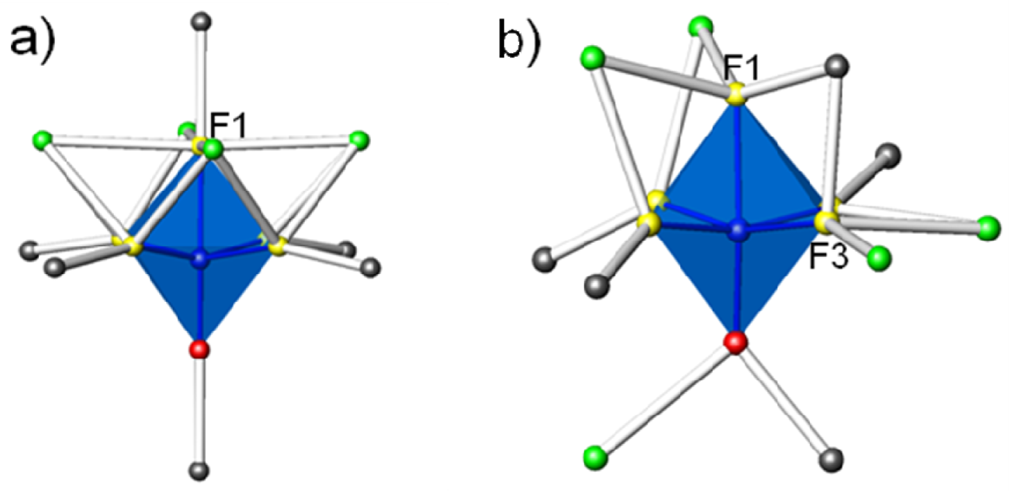
KNaNbOF5 has a noncentrosymmetric polymorph [20]. The results discussed here on the noncentrosymmetric polymorph can be found in [20]. The different local coordination environments around the centrosymmetric (CS) and noncentrosymmetric (NCS) [NbOF5]2- structures are illustrated in Figure 3. In the NCS polymorph the two fluorides F1 and F3 contain the largest residual negative charge (0.48 and 0.23 vu, respectively) and make three contacts with two eight-coordinate K+ and one six-coordinate Na+. In the CS polymorph, one fluoride, F1, has the largest residual negative charge (0.58 vu) and makes four contacts with four twelve-coordinate K+ and one six-coordinate Na+. Although there are fewer Na–F interactions than K–F in both the NCS and CS polymorphs, the Na–F interactions are stronger, as seen by their shorter bond lengths and higher bond valences. As a result, in the CS polymorph the Na+ cation is slightly more over bonded (1.22 vu) compared to K+ (1.08 vu).
The oxides in both the NCS and CS polymorph are under bonded. In the NCS polymorph, the oxide is three-coordinate with one K+ and one Na+ contact and a Nb=O bond at 1.745(5) Å. In the CS polymorph, the oxide is two-coordinate and makes one Na+ contact and as expected there is a shorter Nb=O bond distance of 1.7179(14) Å. Conversely, the extra K+ contact in the NCS polymorph results in a longer Nb=O bond.
In a perovskite with B-site rock-salt ordering the A-site cations prefer to order in a layered arrangement which is stabilized by the presence of a second order Jahn Teller displacement of at least one d0 transition metal at the B-site [10,11]. In NaLnMnWO6 and NaLnMgWO6 with a trivalent and monovalent A-site cation, the oxides coordinated to the Na+ are under bonded while the oxides coordinated to the Ln3+ are over bonded. To compensate, the d0 transition metal, W6+, at the B-site will shift towards the oxide coordinated to the smaller cation (Na+) and away from the larger cation (Ln3+) to alleviate the lattice strain arising from the size mismatch (Figure 4a). A similar comparison can be made to KNaNbOF5. Instead of having two A-site cations, there is an occupied and unoccupied A-site. As a result, the oxide in the same layer as the unoccupied A-site is under bonded. To compensate, the Nb5+ at the B-site shifts toward the oxide and away from the trans fluoride (Figure 4b). Thus, the long range ordering of the KNaNbOF5 structure results in a centrosymmetric arrangement of the anionic units.
2.4. KNaMO2F4 and partial anionic ordering
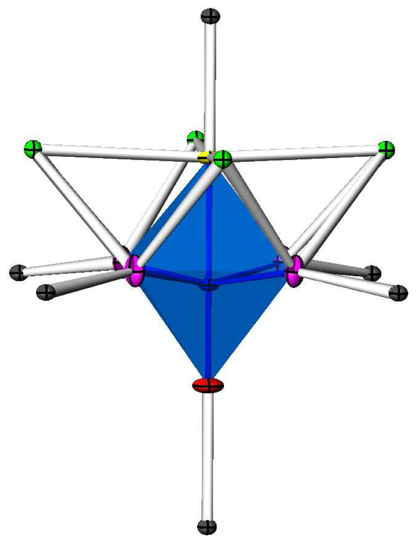
In KNaMO2F4 (M = Mo6+, W6+), the oxide and its trans fluoride are ordered while the second oxide is disordered along with the other three fluorides at the equatorial positions. Despite the partial ordering of the oxide and fluoride, the A- and B-site cations are ordered. The partial ordering of the anionic unit has been reported previously, where Mo/W distorts towards the corner as opposed to the edge [22,23]. The partial ordering of the oxide and fluoride is due to the symmetric environment around the equatorial positions. In KNaNbOF5, the bond network at the oxide differs from the trans fluoride; therefore, the oxide can be identified based on bond lengths. When two oxides are present as in KNaMO2F4, one oxide is ordered (Figure 5). The bond lengths of the oxide and the trans fluoride at the axial positions are different, which we use to identify the oxide and fluoride sites. However, at the equatorial positions, the bond length is the average of the four bonds from the second oxide and three fluorides, therefore the second oxide and three fluorides are not differentiated. In addition, bond valence sums cannot be accurately calculated because it is dependent on the observed bond lengths.
3. Experimental Section
3.1. Materials and synthesis
Caution
Hydrofluoric acid is toxic and corrosive, and must be handled with extreme caution and the appropriate protective gear! If contact with the liquid or vapor occurs, proper treatment procedures should immediately be followed [30-32].
Materials
Nb2O5(99.9%, Aldrich), Na2MoO4•2H2O (99.9%, Aldrich), Na2WO4•2H2O (99.9%, Aldrich), NaF (99.9%, Aldrich), KF (99.9%, Aldrich), and aqueous hydrofluoric acid (HF) (48% HF by weight, Aldrich) were used as received. Owing to their hygroscopic nature, the alkali fluorides were weighed under nitrogen in a dry box.
All reactants were sealed in Teflon [fluoro(ethylenepropylene), FEP] “pouches” [33]. Single or multiple pouches were placed in a 125 mL Teflon-lined Parr pressure vessel filled 33% with deionized H2O as backfill [34]. The pressure vessel was heated for 24 h at 150 °C and cooled to room temperature over an additional 24 h. The pouches were opened in air, and the products were recovered by vacuum filtration.
KNaNbOF5
KNaNbOF5 was synthesized by reacting NaF (0.0790g, 0.0019 mol), KF (0.1639g, 0.0028 mol), Nb2O5 (0.25g, 0.0009 mol) and 48% aqueous HF (0.5000 g, 0.0250 mol). Colorless plates were recovered in 68% yield based on Nb.
KNaMoO2F4
KNaMoO2F4 was synthesized by reacting KF (0.0600g, 0.0010 mol), Na2MoO4•2H2O (0.25g, 0.0010 mol) and 48% aqueous HF (0.2500 g, 0125 mol). Colorless plates were recovered in 66% yield based on Mo.
KNaWO2F4
KNaWO2F4 was synthesized by reacting KF (0.0440g, 0.0008 mol), Na2WO4•2H2O (0.25g, 0.0008 mol) and 48% aqueous HF (0.2500 g, 0.0125 mol). Colorless plates were recovered in 72% yield based on W.
3.2. Crystallographic determination
Single crystal X-ray diffraction data of KNaNbOF5, KNaMoO2F4 and KNaWO2F4 were collected with Mo-Kα radiation (0.71073 Å) on a Bruker APEX2 CCD diffractometer and integrated with the SAINT-Plus program [35]. The structures were solved by direct methods and refined against F2 by full-matrix least-squares techniques with SHELX. A face-indexed absorption correction was performed numerically using the program XPREP. All structures were checked for missing symmetry elements with PLATON [36]. The final refinement includes anisotropic displacement parameters. Further details of the crystal structure investigations may be obtained from Fachinformationszentrum Karlsruhe, 76344 Eggenstein-Leopoldshafen, Germany (fax: (+49)7247-808-666; e-mail: [email protected], http://www.fiz-karlsruhe.de/request_for_deposited_data.html) on quoting the 422708 (KNaNbOF5), 422707 (KNaMoO2F4) and 422709 (KNaWO2F4) CSD numbers. Crystallographic data for KNaNbOF5 and KNaMO2F4, (M = Mo6+, W6+) are given in Table 4.
3.3. Spectroscopic measurements
Mid-infrared (600–4000 cm-1) spectra of KNaNbOF5, KNaMoO2F4 and KNaWO2F4 were collected using a Bruker 37 Tensor FTIR spectrometer equipped with an ATR germanium cell attachment operating at a resolution of 2 cm-1.
4. Conclusions
The interactions of the [NbOF5]2- and [MO2F4]2- anionic units with the cationic bond network (Na+ and K+) influences the long range ordering of the anionic units. The oxide coordinated to the unoccupied A-sites is under bonded. To compensate, the d0 transition metal (Nb/M) shifts towards the oxide coordinated to the unoccupied A-site and away from the fluoride coordinated to the K+ to satisfy PSCR. These interactions in KNaNbOF5 and KNaMO2F4 lead to a rock salt ordering of the B-site cations and an ordered layering of the occupied and unoccupied A-sites resulting in a centrosymmetric arrangement.


| Bond Distances (Å) | |||||||||||
|---|---|---|---|---|---|---|---|---|---|---|---|
| Nb-O | 1.7179(14) | Mo-O | 1.6718(16) | W-O | 1.698(3) | ||||||
| Nb-F2 | 2.1473(h) | Mo-F2 | 2.1110(12) | W-F2 | 2.100(2) | ||||||
| Nb-F3 x 4 | 1.9552(7) | Mo-X3 x 4 | 1.9074(7) | W-X3 x 4 | 1.9033(13) | ||||||
| Na-O | 2.2961(16) | Na-O | 2.3408(17) | Na-O | 2.298(3) | ||||||
| Na-F2 | 2.3501(14) | Na-F2 | 2.3360(14) | Na-F2 | 2.394(3) | ||||||
| Na-F3 x 4 | 2.2754(7) | Na-X3 x 4 | 2.2766(7) | Na-X3 x 4 | 2.2938(13) | ||||||
| Bond Angles | |||||||||||
| O-Nb-F2 | 180.00° | O-Mo-F2 | 180.00° | O-W-F2 | 180.00° | ||||||
| O-Nb-F3 | 99.364(18)° | O-Mo-X3 | 99.07(2)° | O-W-X3 | 99.03(4)° | ||||||
| F2-Nb-F3 | 80.636(18)° | F2-Mo-X3 | 80.93(2)° | F2-W-X3 | 80.97(4)° | ||||||
| Nb-O-Na | 180.00° | Mo-O-Na | 180.00° | W-O-Na | 180.00° | ||||||
| Nb-F2-Na | 180.00° | Mo-F2-Na | 180.00° | W-F2-Na | 180.00° | ||||||
| Nb-F3-Na | 162.50(4)° | Mo-X3-Na | 164.03(5)° | W-X3-Na | 162.11(8)° | ||||||
| KNaNbOF5 | K | Na | Nb | Vi = Σi Sij | |
|---|---|---|---|---|---|
| Rij (Å) | O1 | 2.2961(16) | 1.7179(14) | ||
| Sij (vu) | 0.26 | 1.69 | 1.95 | ||
| Rij (Å) | F2 | 2.9586(9) | 2.3501(14) | 2.1473(11) | |
| Sij (vu) | 0.07 | 0.16 | 0.42 | 0.88 | |
| Rij (Å) | F3 | 2.8492(4) | 2.2754(7) | 1.9552(7) | |
| Sij (vu) | 0.10 | 0.20 | 0.71 | 1.11 | |
| Vj = Σj Sij | 1.08 | 1.22 | 4.95 | ||
Rij = bond length of the bond ″ij″; Sij = exp[R0−Rij)/B] experimental bond valence of bond ″ij″, where R0 = constant dependent on i and j bonded elements, and B = 0.37; R0(Nb–O) = 1.911, R0(Nb–F) = 1.87 ; R0(Na–O) = 1.803, R0(Na–F) = 1.677; sij = theoretical bond valence of bond “ij”, calculated by solving the network equations based on the methods described by Brown [27,28]; Vi, Vj = experimental valences of anions “i” and cations “j”.; zi, zj = charge or formal valence of anions “i” and cations “j”.
| KNaNbOF5 | |||||||
|---|---|---|---|---|---|---|---|
| Bond | Anionic BV (vu) a | Cationic PSCR sum (vu) b | Cationic BV sum (vu) c | ||||
| Nb–O1 | 0.31 | 0.17 | 0.26 | ||||
| Nb–F2 | 0.58 | 0.50 | 0.46 | ||||
| Nb–F3 | 0.29 | 0.33 | 0.40 |
aAnionic BV (Bond Valence) = zi−SNb−O/F, where zi is the electric charge of each ligand and SNb−O/F is taken from the Table 2 for each Nb−O/F bond;bCationic PSCR sum =
| Formula | KNaNbOF5 | KNaMoO2F4 | KNWO2F4 |
|---|---|---|---|
| fw | 266.00 | 266.03 | 353.94 |
| Space group | P4/nmm (No. 129) | P4/nmm (No. 129) | P4/nmm (No. 129) |
| a (Å) | 5.91390(10) | 5.8600(2) | 5.86350(10) |
| c (Å) | 8.5114(2) | 8.45960(10) | 8.49070(10) |
| V(Å3) | 297.680(10) | 290.499(3) | 219.916(8) |
| Z | 2 | 2 | 2 |
| T(K) | 100(2) | 100(2) | 100(2) |
| λ(Å) | 0.71073 | 0.71073 | 0.71073 |
| ρcalc(g/cm3) | 2.968 | 3.041 | 4.027 |
| μ (mm-1) | 2.812 | 3.055 | 20.579 |
| R(F)a | 0.0102 | 0.0163 | 0.0111 |
| wR2(F2)b | 0.0274 | 0.0342 | 0.0248 |
aR=Σ| |Fo|−|Fc| |/Σ|Fo|;bwR2=[Σw(Fo2−Fc2)2/Σw(Fo2)2]1/2
Acknowledgments
The authors thank Michael R. Marvel for valuable insights and discussions and Martin Donakowski for the IR measurements of KNaNbOF5, KNaMoO2F4 and KNaWO2F4. The authors gratefully acknowledge the support from the National Science Foundation (Solid State Chemistry Award Nos. DMR-0604454 and DMR-1005827) and the use of the Central Facilities supported by the MRSEC program of the National Science Foundation (DMR-0076097 and DMR-0520513) at the Materials Research Center of Northwestern University.
References and Notes
- Shimakawa, Y. A-Site Ordered Perovskites with Intriguing Physical Properties. Inorg. Chem. 2008, 47, 8562–8570. [Google Scholar]
- Stramare, S.; Thangadurai, V.; Weppner, W. Lithium Lanthanum Titanates: A Review. Chem. Mater. 2003, 15, 3974–3990. [Google Scholar]
- Brink, F.J.; Norén, L.; Goossens, D.J.; Withers, R.L.; Liu, Y.; Xu, C.-N. A combined diffraction (XRD, electron and neutron) and electrical study of Na3MoO3F3. J. Solid State Chem. 2003, 174, 450–458. [Google Scholar]
- Woodward, P.M.; Karen, P. Mixed Valence in YBaFe2O5. Inorg. Chem. 2003, 42, 1121–1129. [Google Scholar]
- Chakhmouradian, A.R.; Mitchell, R.H.; Burns, P.C. The A-site deficient ordered perovskite Th0.25□0.75NbO3: a re-investigation. J. Alloys Compounds 2000, 307, 149–156. [Google Scholar]
- Iyer, P.N.; Smith, A.J. Double Oxides Containing Niobium, Tantalum, or Protactinium. III. Systems Involving the Rare Earths. Acta Crystallogr. 1967, 23, 740. [Google Scholar]
- Kennedy, B.J.; Howard, C.J.; Kubota, Y.; Kenichi, K. Phase transition behavior in the A-site deficient perovskite oxide La1/3NbO3. J. Solid State Chem. 2004, 177, 4552–4556. [Google Scholar]
- Sefat, A.S.; Amow, G.; Wu, M.-Y.; Botton, G.A.; Greedan, J.E. High-resolution EELS study of the vacancy-doped metal/insulator system, Nd1-xTiO3, x = 0 to 0.33. J. Solid State Chem. 2005, 178, 1008–1016. [Google Scholar]
- Dupont, L.; Chai, L.; Davies, P.K. A- and B-site ordered in (Na1/2La1/2)(Mg1/3Ta2/3)O3 Perovskites. Mater. Res. Soc. Symp. P. 1998, 547, 93–98. [Google Scholar]
- King, G.; Wayman, L.M.; Woodward, P.M. Magnetic and structural properties of NaLnMnWO6 and NaLnMgWO6. J. Solid State Chem. 2009, 182, 1319–1325. [Google Scholar]
- Knapp, M.C.; Woodward, P.M. A-site cation ordering in AA′BB′O6 perovskites. J. Solid State Chem. 2006, 179, 1076–1085. [Google Scholar]
- Anderson, M.T.; Greenwood, K.B.; Taylor, G.A.; Poeppelmeier, K.R. B-Cation Arrangements in Double Perovskites. Prog. Solid State Chem. 1993, 22, 197–233. [Google Scholar]
- Howard, C.J.; Kennedy, B.J.; Woodward, P.M. Ordered double perovskites - a group-theoretical analysis. Acta Crystallogr. B 2003, 59, 463–471. [Google Scholar]
- Lufaso, M.W.; Barnes, P.W.; Woodward, P.M. Structure prediction of ordered and disordered multiple octahedral cation perovskites using SPuDS. Acta Crystallogr. B 2006, 62, 397–410. [Google Scholar]
- Barnes, P.W.; Lufaso, M.W.; Woodward, P.M. Structure determination of A2M3+TaO6 and A2M3+NbO6 ordered perovskites: octahedral tilting and pseudosymmetry. Acta Crystallogr. B 2006, 62, 384–396. [Google Scholar]
- Woodward, P.; Hoffmann, R.D.; Sleight, A.W. Order-disorder in A2M3+M5+O6 perovskites. J. Mater. Res. 1994, 9, 2118–2127. [Google Scholar]
- Flerov, I.N.; Gorev, M.V.; Tressaud, A.; Laptash, N.M. Perovskite-Like Fluorides and Oxyfluorides: Phase Transitions and Caloric Effects. Crystallogr. Rep. 2011, 56, 9–17. [Google Scholar]
- Vasiliev, A.D.; Zaitsev, A.; Cherepakhin, A.V.; Laptash, N.M. Polymorphic Modification of Crystal SrB4O7 and KNaNbOF5. Phase Transit., Ordered State., New Mater. 2010, 11, 2. [Google Scholar]
- Izumi, H.K.; Kirsch, J.E.; Stern, C.L.; Poeppelmeier, K.R. Examining the Out-of-Center Distortion in the [NbOF5]2- Anion. Inorg. Chem. 2005, 44, 884–895. [Google Scholar]
- Marvel, M.R.; Lesage, J.; Baek, J.; Halasyamani, P.S.; Stern, C.L.; Poeppelmeier, K.R. Cation-Anion Interactions and Polar Structures in the Solid State. J. Am. Chem. Soc. 2007, 129, 13963–13969. [Google Scholar]
- Pausewang, G.; Schmitt, R.; Dehnicke, K. Vibrational-Spectra of Oxofluoro Complexes of Species NbOF52-, TaOF52-, MoO2F42-, WO2F42-, NbOF63-, and MoO2F53-. Z Anorg. Allg. Chem. 1974, 408, 1–8. [Google Scholar]
- Heier, K.R.; Norquist, A.J.; Halasyamani, P.S.; Duarte, A.; Stern, C.L.; Poeppelmeier, K.R. The polar [WO2F4]2- anion in the solid state. Inorg. Chem. 1999, 38, 762–767. [Google Scholar]
- Marvel, M.R.; Pinlac, R.A.F.; Lesage, J.; Stern, C.L.; Poeppelmeier, K.R. Chemical Hardness and the Adaptive Coordination Behavior of the d0 Transition Metal Oxide Fluoride Anions. Z Anorg. Allg. Chem. 2009, 635, 869–877. [Google Scholar]
- Pauling, L. The principles determining the structure of complex ionic crystals. J. Am. Chem. Soc. 1929, 51, 1010–26. [Google Scholar]
- Tobias, G.; Beltran-Porter, D.; Lebedev, O.I.; Van Tendeloo, G.; Rodriguez-Carvajal, J.; Fuertes, A. Anion Ordering and Defect Structure in Ruddlesden-Popper Strontium Niobium Oxynitrides. Inorg. Chem. 2004, 43, 8010–8017. [Google Scholar]
- Brown, I.D.; Altermatt, D. Bond-valence parameters obtained from a systematic analysis of the inorganic crystal structure database. Acta Crystallogr. B Struct. Sci. 1985, B41, 244–247. [Google Scholar]
- Brown, I.D. The Chemical Bond in Inorganic Chemistry: The Bond Valence Model, 1st ed.; Oxford University Press: Oxford, UK, 2002; Volume 1, p. 278. [Google Scholar]
- Brown, I.D. Recent developments in the bond valence model of inorganic bonding. Phys. Chem. Miner. 1987, 15, 30–34. [Google Scholar]
- Shannon, R.D.; Fischer, R.X. Emperical electronic polarizabilities in oxides, hydroxides, oxyfluorides, and oxychlorides. Phys. Rev. B 2006, 73, 235111. [Google Scholar]
- Bertolini, J.C. Hydrofluoric acid: a review of toxicity. J. Emerg. Med. 1992, 10, 163–168. [Google Scholar]
- Peters, D.; Miethchen, R. Symptoms and treatment of hydrogen fluoride injuries. J. Fluorine Chem. 1996, 79, 161–165. [Google Scholar]
- Segal, E.B. First aid for a unique acid, HF: A sequel. Chem. Health Safety 2000, 7, 18–23. [Google Scholar]
- Harrison, W.T.A.; Nenoff, T.M.; Gier, T.E.; Stucky, G.D. Tetrahedral-atom 3-ring groupings in 1-dimensional inorganic chains: beryllium arsenate hydroxide hydrate (Be2AsO4OH·4H2O) and sodium zinc hydroxide phosphate hydrate (Na2ZnPO4OH·7H2O). Inorg. Chem. 1993, 32, 2437–2441. [Google Scholar]
- Norquist, A.J.; Heier, K.R.; Stern, C.L.; Poeppelmeier, K.R. Composition space diagrams for mixed transition metal oxide fluorides. Inorg. Chem. 1998, 37, 6495–6501. [Google Scholar]
- Bruker Analytical X-ray Instruments, Inc. SAINT-Plus; version 6.02A; Bruker Analytical X-ray Instruments, Inc.: Madison, WI, USA, 2000. [Google Scholar]
- Spek, A.L. PLATON; Utrecht University: Utrecht, The Netherlands, 2001. [Google Scholar]
© 2011 by the authors; licensee MDPI, Basel, Switzerland. This article is an open access article distributed under the terms and conditions of the Creative Commons Attribution license (http://creativecommons.org/licenses/by/3.0/).
Share and Cite
Pinlac, R.A.F.; Stern, C.L.; Poeppelmeier, K.R. New Layered Oxide-Fluoride Perovskites: KNaNbOF5 and KNaMO2F4 (M = Mo6+, W6+). Crystals 2011, 1, 3-14. https://doi.org/10.3390/cryst1010003
Pinlac RAF, Stern CL, Poeppelmeier KR. New Layered Oxide-Fluoride Perovskites: KNaNbOF5 and KNaMO2F4 (M = Mo6+, W6+). Crystals. 2011; 1(1):3-14. https://doi.org/10.3390/cryst1010003
Chicago/Turabian StylePinlac, Rachelle Ann F., Charlotte L. Stern, and Kenneth R. Poeppelmeier. 2011. "New Layered Oxide-Fluoride Perovskites: KNaNbOF5 and KNaMO2F4 (M = Mo6+, W6+)" Crystals 1, no. 1: 3-14. https://doi.org/10.3390/cryst1010003