The Origin of Raman D Band: Bonding and Antibonding Orbitals in Graphene

Abstract
: In Raman spectroscopy of graphite and graphene, the D band at ~ 1355 cm−1 is used as the indication of the dirtiness of a sample. However, our analysis suggests that the physics behind the D band is closely related to a very clear idea for describing a molecule, namely bonding and antibonding orbitals in graphene. In this paper, we review our recent work on the mechanism for activating the D band at a graphene edge.1. Introduction
Bonding and antibonding orbitals are basic ideas for describing molecules. Bonding orbitals contribute to the formation of a molecule, whereas antibonding orbitals weaken the bonding and destabilize a molecule. Normally, bonding orbitals are more stable than antibonding orbitals in terms of energy and thus a molecule is stable unless sufficient electrons occupy the antibonding orbitals.
Graphene [1,2] is unique with respect to its molecular orbitals. The bonding and antibonding orbitals in graphene are degenerate, and various types of linear combination of these orbitals form the Fermi surface expressed by the isoenergy sections of Dirac cones. This degeneracy plays an essential role in various phenomena. For example, graphene is stable with respect to a large shift of the Fermi energy position [3]. Another notable example is that graphene exhibits high mobility. Elastic backward scattering between the bonding and antibonding orbitals induced by long-range impurity potential is suppressed because they are orthogonal [4]. In this paper, we show that the bonding and antibonding orbitals in graphene are key factors in the activation mechanism of the D band observed at a graphene edge.
Since the discovery of the D band, much interest has focused on its origin. Tuinstra and Koenig attributed the D band to an A1g zone-boundary mode at the edge of a sample (see Figure 1) on the grounds that the Raman intensity is proportional to the edge percentage and that the edge causes a relaxation of the momentum conservation needed for activating a zone-boundary phonon [5]. Katagiri et al. confirmed that the D band originates from an edge (or discontinuity in the carbon network) by observing the light polarization dependence of the D band intensity at graphite edge planes [6]. The atomic arrangement of an edge has two principal axes: armchair and zigzag edges. Cançado et al. showed that the armchair (zigzag) edge is relevant (irrelevant) to the relaxation of the momentum conservation for a zone-boundary phonon [7]. In addition, they found that the D band Raman intensity depends on the polarization of laser light, that is, the intensity is maximum (minimum) when the polarization is parallel (perpendicular) to the armchair edge. The light polarization dependence of the D band is also observed ubiquitously at the armchair edges of a single layer of graphene, which suggests that out-of-plane coupling in graphite is not essential to the origin of the D band [8–10].
A model of the D band must at least explain the observed properties: the D band intensity increases only at an armchair edge and is dependent on the laser light polarization.
The current D band model is a double resonance model [11]. In this model, a photo-excited electron passes through two resonance states, which enhances the Raman intensity of a phonon with nonzero wave vector q ≠ 0. This model is not concerned with the details of electron-phonon and electron-light matrix elements, and it does not provide clear explanations of the properties of the D band. Also, the intensity calculated with this model is dependent on the lifetime of the resonance states. Usually, the lifetime is determined in such a manner that a calculated result reproduces experimental data. In this sense, the double resonance model is phenomenological. Because the lifetime is shorter in a defective graphene sample, double resonance does not necessarily mean an enhancement of the D band Raman intensity. On the other hand, the model can account for the so-called dispersive behavior of the D band [11]. However, as we will show in this paper, dispersive behavior is characteristic of A1g modes, rather than an inherent property of the D band. In fact, dispersive behavior is observed also for the 2D band [12], and the excitation does not need an edge, which is in contrast to the D band.
In this paper we show that the observed properties of the D band are naturally explained in terms of simple ideas based on molecular orbitals and momentum conservation. In our formulation, the D band is excited from a photo-excited electron through a single resonance process in the same way as the G band. (Negri et al. took the same approach to the resonance Raman process of the D band of polycyclic aromatic hydrocarbons [13]) It is concluded that, without invoking an artificial assumption, the D band is closely related to (1) the orbital dependence of the electron-phonon matrix element; (2) the special nature of the armchair edge; and (3) optical anisotropy [14].
This paper is organized as follows. In Section 2 we observe that a graphene molecular orbital and wave vector are closely correlated. This correlation is both an important factor in terms of understanding the D band and an essential feature of graphene. In Section 3 the properties of the D band are deduced from three factors (1,2,3). The importance of the electron-phonon matrix element and the role of the armchair edge in the excitation mechanism of the D band are explained in detail. In Section 4 we show some predictions obtained with our model. Future prospects and our conclusion are given in Section 5 and Section 6, respectively. We give some notes on resonant condition in Appendix A.
2. Bonding and Antibonding Orbitals
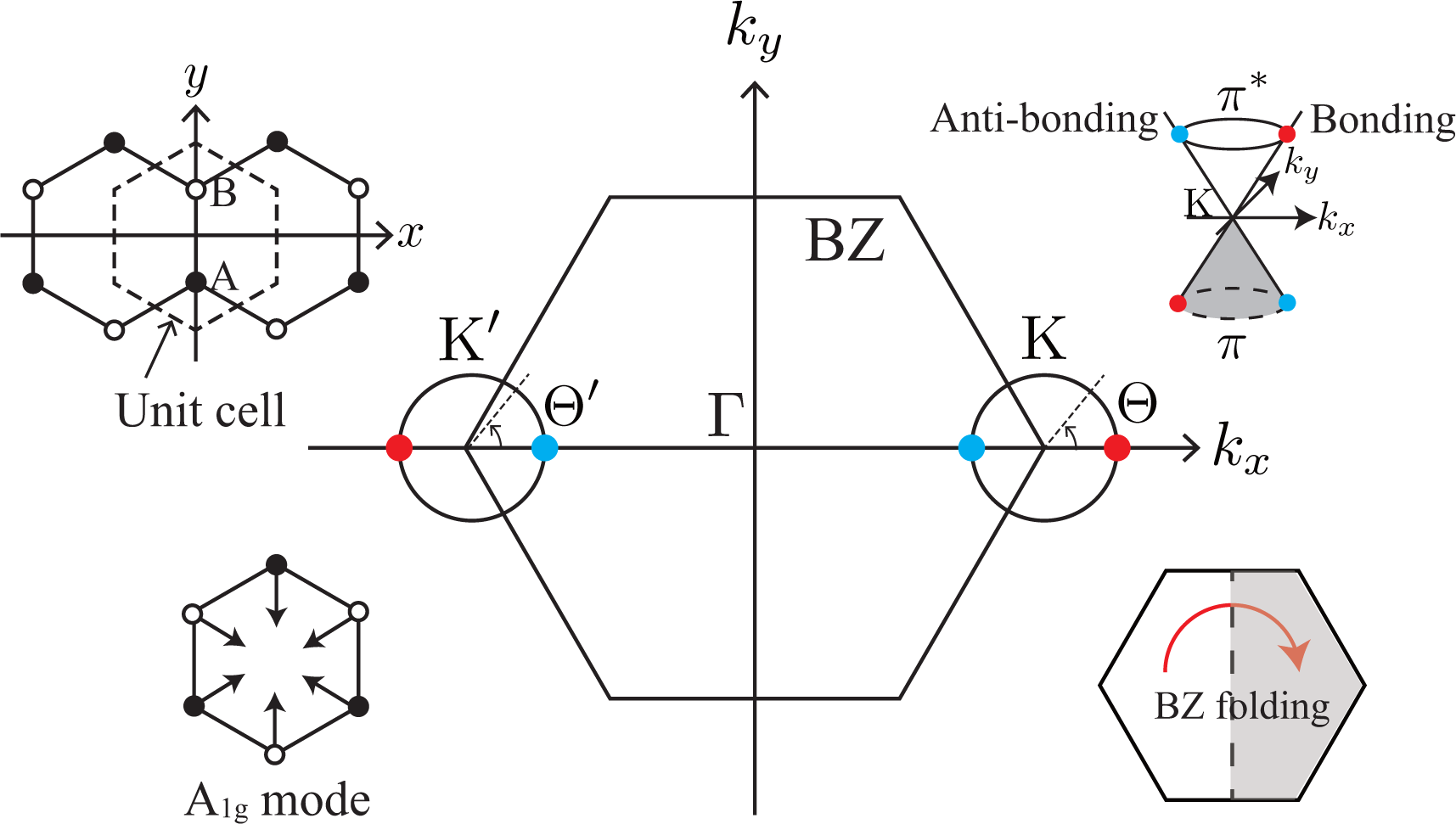
Graphene’s hexagonal unit cell has two carbon atoms, denoted by A and B in Figure 1, and the electron’s wave function ψ is written as a linear combination of 2pz atomic orbitals of the A and B atoms, χA and χB. When we apply Bloch’s theorem to graphene, we obtain ψ and the band structure as a function of the wave vector k [15,16]. In the Brillouin zone (BZ) of graphene, there are two points, namely the K and K′ points, where the conduction and valence bands touch each other. The orbitals of the states near the K point take the form of
In Equation (1), the bonding and antibonding orbitals (χA + χB and −χA + χB) are located at Θ = 0 and π, respectively, on the iso-energy section of the π*-band (s = +1). The orbital with a general Θ is a linear combination of the bonding and antibonding orbitals. In Equation (2), the bonding and antibonding orbitals are located at Θ′ = π and 0, respectively, on the iso-energy section of the π*-band. As we can see in Figure 1, the bonding (antibonding) orbitals are located symmetrically on the kx-axis with respect to the Γ point, which is one of the most important characteristics of the BZ of graphene [i.e., mirror symmetry with respect to the replacement, x ↔ −x].
The orbital Equations (1) and (2) can be derived from an effective model for graphene, that is, a massless Dirac equation, in the following manner. The energy eigenequation is written as
The massless Dirac equation in Equation (3) is decomposed into two Weyl’s equations for the K and K′ valleys: and respectively. To reproduce Equation (1), we assume the plane wave solution and obtain the energy eigenequation ħvFσ·kψK(k)= EψK(k). Then, the corresponding energy eigenvalue and eigenstate are easy to find using as E=sħvF|k| and
This is identical to Equation (1) by setting
Similarly, we can check that Equation (2) is the solution of ħvFσ′·kψK′(k)= EψK′(k), which is given by
The Dirac equation is very helpful as regards understanding the mechanism of a result in terms of symmetry and momentum conservation. In particular, the fact that the Dirac equation is composed of a multiplication of the Pauli matrices (for the A and B atoms) and momentum operators makes it easy to recognize that the orbital (the pattern of the linear combination of χA and χB) is dependent on the wave vector of the particle. In the following, we refer to the Dirac equation for graphene in order to capture the essential features of a result. The graphene Dirac equation differs from the original Dirac equation in the following respect: the wave function ψ in the graphene Dirac equation has 4 components consisting of two orbitals (χA and χB) and two valleys (K and K′), while those in the original Dirac equation are two spin states (up and down spins) and two chiralities (left- and right-handed) [17]. Thus, the orbital degree of graphene is commonly referred to as pseudo-spin. (We define the bonding and antibonding orbitals by the molecular orbitals of nearest neighbor atoms having the same position in the x-axis (as shown in Figure 1). Although our definition is not appropriate for the bonds between nearest neighbor atoms having different positions in the x-axis, those are not so important in discussing the D band at armchair edge [14]. Note also that our definition connects smoothly to the definition of π and π* bands at the Γ point, where any nearest neighbor carbon atoms form the bonding (antibonding) orbital in the π (π*) band.)
3. Light Polarization Dependence of D Band Intensity
In this section we show that the light polarization dependence of the D band originates from three factors. The first factor concerns the nature of the electron-phonon interaction for the A1g mode, which will be explained in Section 3.1. The second factor is a modification of the BZ by the armchair edge, which will be explored in Section 3.2. In Section 3.3, we describe the third factor, which concerns the interaction between electrons and a polarized laser light. In Section 3.4, we construct the D band polarization formula, by combining the three factors.
3.1. Dominance of Intervalley Backward Scattering
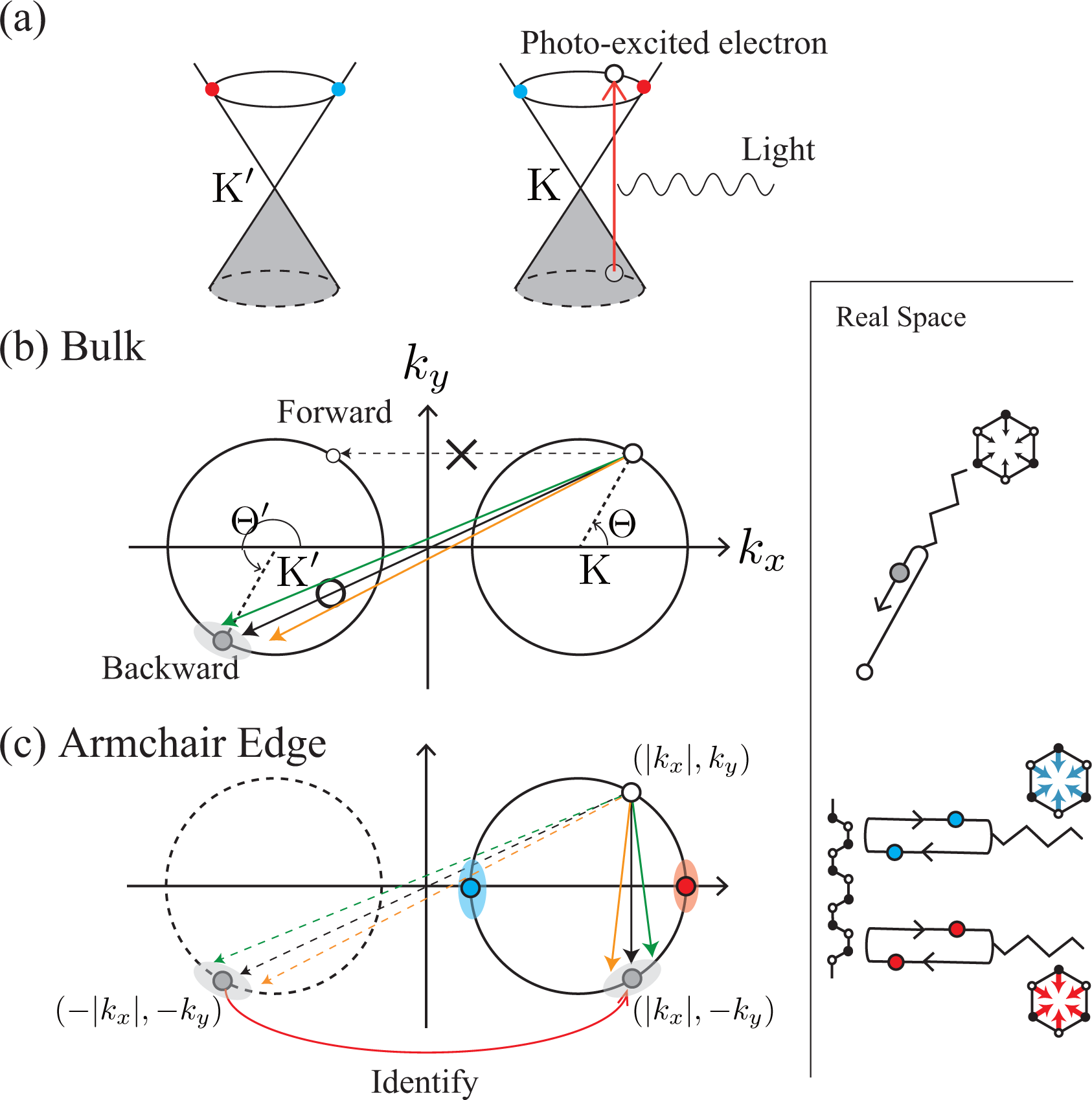
Suppose that an electron has been excited into the π*-band by a laser light [Figure 2a]. When a photo-excited electron emits an A1g mode, there is a strong probability that the electron will undergo (intervalley) backward scattering, as shown by the real space diagram in Figure 2b. In the k-space, the change in the exact (approximate) intervalley backward scattering is denoted by the black (orange and green) solid arrow. Although the forward scattering denoted by the dashed arrow may be allowed by momentum conservation, it never takes place because orbitals suppress the corresponding electron-phonon matrix element. This dominance of intervalley backward scattering originates from the characteristic feature of an A1g mode, namely that the vibration consists only of bond shrinking/stretching motions, as shown by the displacement vectors in Figure 1. Mathematically, this characteristic of the A1g mode is described by the fact that the electron-phonon interaction, Ĥep(D), satisfies
Equation (10) shows that, for intraband scattering (ss′ = 1), the scattering probability of the exact backward scattering (Θ′ = Θ + π) is maximum, while that of the exact forward scattering (Θ′ = Θ) vanishes.
When the energy of a photo-excited electron is much larger than the phonon energy (≃ 0.15 eV), we can assume that no significant energy shift occurs as a result of the inelastic scattering. For the exact backward scattering, the A1g wave vector relates to the photo-excited electron wave vector as q = −2k, where q (k) is the wave vector of the A1g mode (photo-excited electron) measured from the K point. This relationship between k and q shows that the orbitals effectively relate the electron wave vector k to the A1g wave vector q. (Thus, the orbital dependence of the electron-phonon matrix element justifies the basic idea of the quasi-selection rule for the D band proposed by several authors [18,19]. The relationship between k and q (q = −2k) shows that ħvF|q| changes linearly with changing excitation energy EL because 2ħvF|k| is approximately equal to EL. It becomes important when we discuss the dispersive behavior of the D band in Section 4.1).
It is straightforward to reproduce Equation (10) in the framework of the graphene Dirac equation. The electron-phonon interaction for an A1g mode with wave vector q is written as [20]
The last line is written as a multiplication of two parts: the first part represents momentum conservation and the wave vector of the scattered electron k′ is given by k′ = k + q. The second part gives Equation (10). In addition to momentum conservation, we can use energy conservation to obtain vF|k′| = vF|k| − ωq, where ωq is the frequency of A1g. Thus, when ħvF|k| ≫ ħωq, we have |k′| ≃ |k|. Since the orbital part results in the dominance of intervalley backward scattering, we obtain k′ ≃ −k. As a result, q ≃ −2k is satisfied.
3.2. Brillouin Zone Folding
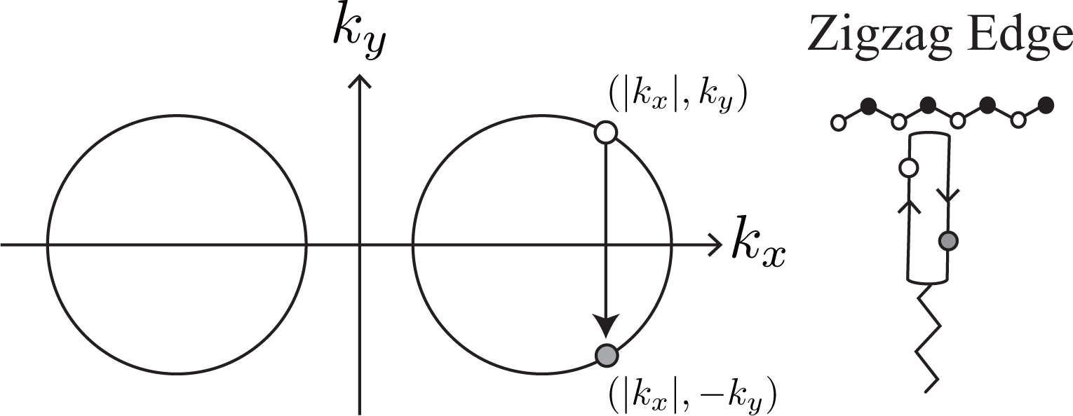
The dominance of intervalley backward scattering causes an enhancement of the D band Raman intensity if Brillouin zone folding (BZF) by the armchair edge is taken into account [14]. Here, BZF means that, in the BZ of graphene shown in Figure 1, a state with (kx, ky) is identical to a state with (−kx, ky) and that the correct BZ is given by the positive kx region of the original BZ of graphene [21]. In Figure 2c, as a consequence of BZF, the final state in the intervalley backward scattering event is identified with the state near the K point. Namely, the state with (−|kx|, −ky) near the K′ point is identified with the state with (|kx|, −ky) near the K point. So, in the folded BZ, the change of a photo-excited electron is (|kx|, ky) → (|kx|, −ky), as shown by the solid arrow in Figure 2c. Generally, the probability of a process in the folded BZ is given by replacing Θ′ with π − Θ′ in Equation (10) as
BZF originates from the fact that a special standing wave is formed by an armchair edge. The standing wave is constructed by the antisymmetric combination of an incident plane wave with k = (kx, ky) and a scattered plane wave with k′ = (−kx, ky) as A symmetric combination does not satisfy the boundary condition for the armchair edge [21]. Note that sin(kxx) does not change when kx is replaced with −kx, except for the unimportant change in the overall sign. More importantly, the orbital part Equation (1) does not change when there is the reflection at the armchair edge, as we can confirm by replacing Θ′ with π − Θ in Equation (2) [21,22]. The same orbitals are superposed to form a standing wave at the armchair edge. Thus, the total wave function becomes
The standing wave at the armchair edge can be expressed in the framework of the Dirac equation as
3.3. Optical Anisotropy
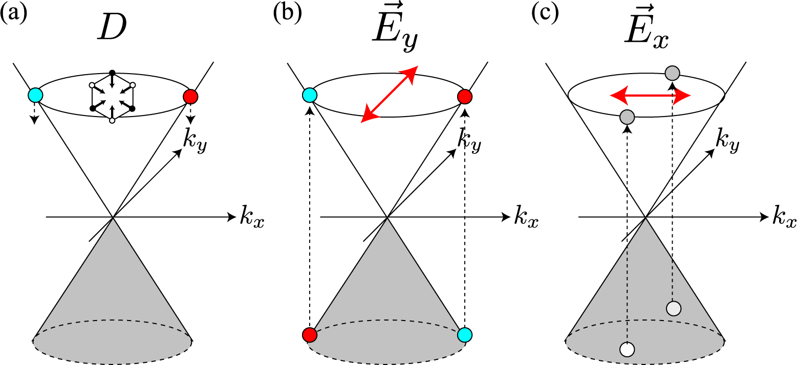
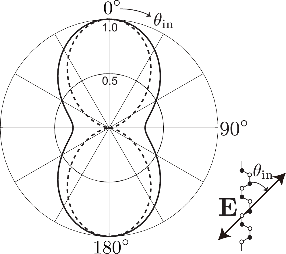
The third factor is the polarization dependence of optical transitions. To supply photo-excited electrons to the states with bonding and antibonding orbitals on the kx-axis, the polarization of incident laser light must be set parallel to the armchair edge (y-axis), as shown in Figure 4b. The photo-excited electrons on the kx-axis emit A1g modes without changing their positions [see Figure 4a]. Meanwhile, when the polarization of the incident laser light is set perpendicular to the armchair edge, the x-polarized light supplies the states on the ky-axis with photo-excited electrons [see Figure 4c]. The electrons near the ky-axis change their positions in the folded BZ when they emit A1g modes [see Figure 2b], and these electrons on the ky-axis do not contribute to the D band intensity. As a result, the D band can be strongly dependent on the laser light polarization: the D band intensity is enhanced (suppressed) when the polarization of the incident laser light is parallel (perpendicular) to the armchair edge.
The optical anisotropy is due to the Θ dependence of the optical matrix element [26]. Namely, for y (x) polarized light, the optical matrix element squared is proportional to cos2 Θ (sin2 Θ) as
Although Equation (19) was derived without taking account of the edge, it turns out that a similar optical matrix element is obtained for the standing waves [27]. Here, let us use the Dirac equation of Equation (3) to obtain the matrix element that includes the effect of the armchair edge. The electron-light interaction is given by replacing with in Equation (3) as
For the y-polarized light A = (0, Ay), Mopt is nonzero only for a direct transition (k′ = k) and the orbital gives cos Θ. For the x-polarized light A = (Ax, 0), Mopt includes the integral and the orbital gives (−eiΘ′ + e−iΘ)/2. Since the integral vanishes when kx = kx′, a direct transition does not take place. The possible transitions are indirect transitions kx ≠kx′. For kx − kx′ = nπ/L (n is an odd number), we obtain 2/(nπ) by performing the integral. The momentum change in an indirect transition is inversely proportional to the distance (L) from the armchair edge where the standing wave is a good approximation. Since the change in the wave vector is negligible when L is large, we may assume Θ′ ≃ Θ. Then the orbital leads to −i sin Θ, which reproduces Equation (19). This feature of the indirect transition for the x-polarized light has been examined with a more mathematically rigorous method using a lattice tight-binding model [27].
3.4. D Band Polarization Formula
We combine Equations (14) and (19) to derive the polarization formula of the D band. The probability of a first-order Raman process that an electron with Θ in the π-band is excited into the π*-band by and then the photo-excited electron emits the A1g mode, and finally the electron with Θ emits a light with is given by
Note that the wave vector of the A1g mode is completely fixed by Θ and |k| (or EL) as
Phonons with different momenta are distinguishable in principle. We have different final states for different Θ values, and to calculate the D band intensity, we need to sum over all possible final states by operating |Mji(Θ)|2 with . Because , the polarization dependence of the D band intensity is written as
4. Predictions of Our Model
We have seen that the D band has a direct relationship to the bonding and antibonding orbitals (that is, an A1g mode is excited through the first-order Raman process only from these orbitals). This conclusion has been derived based on two factors: the dominance of intervalley backward scattering (Section 3.1), and BZF by the armchair edge (Section 3.2). In this section, we report some consequences that are derived from these factors.
4.1. The Origin of Dispersive Behavior
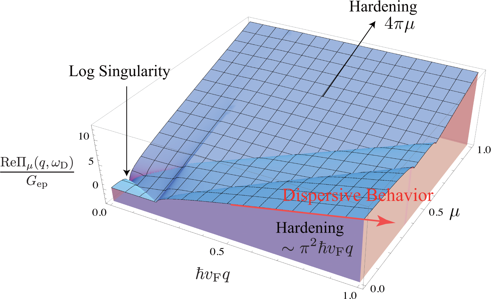
The D band frequency ωD increases linearly with increasing excitation energy EL as ∂ωD/∂EL ∼ 50 cm−1/eV, which is known as dispersive behavior [9,12,29,30]. In a previous paper [31], we pointed out that the dispersive behavior is mainly attributed to a quantum mechanical correction (self-energy) to the A1g frequency. The modified energy of the A1g mode is written as ħω + ReΠμ(q, ω), where ω is the bare frequency (Calculation suggests that the bare frequency contains a term quadratic in q, which is consistent with inelastic X-ray scattering data for graphite [32].) and Πμ(q, ω) represents the self-energies of the A1g modes induced by electron-phonon interaction. The self-energy of an A1g mode with q = |q| is defined as
In the continuum limit of k, Πμ(q, ω) is calculated analytically. The expression of the real part is given by
Since ħvFq ≃ EL, the self-energy contributes to the dispersive behavior of the D (or 2D) band [9,12,29,30,33]. If we use Gep = 5 cm−1/eV, which is obtained from the broadening data published by Chen et al. [3], the self-energy can account for ∼60% of the dispersion because ReΠμ≃0(q, ωq)≃Gepπ2EL and Gepπ2 ≃ 30 cm−1/eV. It should be emphasized that the self-energy is calculated using only Equation (10), and any artificial assumption, such as an adiabatic approximation, is not employed when calculating the self-energy. The physical origin of the dispersive behavior is easy to be understood with shifted Dirac cones [31]. In perturbation theory, the mechanism of dispersive behavior is almost the same as the mechanism where the G band exhibits hardening with increasing |μ|.
The dispersive behavior is not an inherent property of the D band but rather is a property of the A1g mode. The armchair edge is involved in the activation of the D band. However, the dispersive behavior itself has nothing to do with the edge. In other words, there are processes that can exhibit dispersive behavior, besides the Raman D band. A good example is the 2D band, for which dispersive behavior is observed [12] because the 2D band consists of two A1g modes.
4.2. Intravalley Phonons
In addition to the zone-boundary A1g mode, we can determine the effect of BZF on zone-center (intravalley) optical phonon modes: BZF forbids an intravalley transverse optical (TO) mode to appear as a prominent Raman band at the armchair edge. The Dirac equation is the most useful way of showing this. The electron-phonon interactions for the LO and TO modes with (nonzero) momentum (qx, qy) are written as
4.3. D Band Splitting
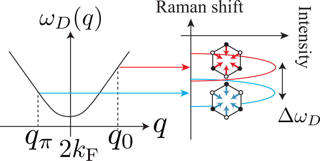
The D band is composed of the (two) A1g modes that are emitted from two electronic states with bonding or antibonding orbitals (Θ = 0 or π). This fact results in the splitting of the D band if the trigonal warping effect is taken into account [14]. The splitting width increases with increasing incident laser energy EL as
For simplicity, let us assume that the phonon dispersion relation for the D band is isotropic about the Dirac point. From Figure 7 it is clear that the two phonon modes with q0 and qπ have different phonon energies, which results in the double peak structure of the D band. The difference between the energy of the phonon mode with q0 and that with qπ is approximated by
Putting |∂EL/∂q| = ħvF in Equation (37), and combining it with Equations (35) and (36), we obtain Equation (34). Actual splitting can be smaller than Equation (34) due to several factors, such as (i) the phonon dispersion relation for the D band not being exactly isotropic around the Dirac point [32]; (ii) Θ not exactly limited by 0 or π.
5. Prospects
The D band has a close relationship with the energy gap. A direct relationship between the zone-boundary A1g mode and the energy gap is seen in the Pierls instability at armchair nanoribbons [36,37]. In the Dirac equation, an energy gap is represented by a Dirac mass term that appears in the off-diagonal terms as
The spectrum has an energy gap 2|m|, because the energy dispersion is given by The zone-boundary A1g mode is related to the Dirac mass because the electron-phonon interaction [Equation (11)] appears as a mass term in the Dirac equation: m → gepe−iq·r. The dominance of intervalley backward scattering becomes clear with respect to the mass term, because a nonzero mass tends to stop a massless particle by backward scattering.
Interestingly, the armchair edge itself can be modeled as a singular mass term in the Dirac equation, whereby Equation (17) is obtained as a solution of the model [38]. This theoretical framework leads us to find a relationship between the dominance of intervalley backward scattering represented by Equation (10) and BZF. To see a connection between them, it is important to recognize that in deriving Equation (10), the orbital structures of Equations (1) and (2) play a decisive role. These orbitals have to relate to each other by mirror symmetry with respect to the x-axis [x → −x or kx → −kx] in Figure 1. In fact, Equation (2) is constructed by replacing Θ with π − Θ′ in Equation (1). The orbital should be invariant under this replacement.
Defects, such as a lattice vacancy and a topological defect, are considered to be sources that increase the D band intensity [c-term in Equation (26)]. This speculation is reasonable, because creating a lattice vacancy inevitably involves the antibonding orbital. Unfortunately, the wave functions and the corresponding BZ in the presence of defects are difficult to construct rigidly in the framework of a tight-binding lattice model. This difficulty prevents us from calculating the electron-phonon matrix element exactly. However, there is the possibility of obtaining a good approximation of the matrix element using the Dirac equation [39–43].
6. Conclusions
An orbital and wave vector are the basic idea for a molecular and a crystal, respectively. Knowing the correlation between them is the key to understand the D band. The D band originates from two orbitals: the bonding and antibonding orbitals on the kx-axis. Observing the D band is the same thing as selecting the two orbitals from the various orbitals that compose the iso-energy section of the Dirac cone. This idea leads us to expect the optical control of edge chiralities [44]. A slight asymmetry between the bonding and antibonding orbitals, induced by the trigonal warping effect, may be important in terms of understanding the stability of the armchair edge under laser light irradiation. A closer study of the D band based on the Dirac equation will be fruitful for a further investigation of the physics of the D band.
Acknowledgments
We were informed that in the case of two-phonons Raman scattering the group velocities of the electron before and after the phonon emission turn out to be anti-parallel with a much higher precision than prescribed by Equation (10). This has been discussed by Basko in Section VI.A of [45], and by Venezuela in Section III.E.2 of [46].
A. Resonance Condition
The probability amplitude of a Raman process that contributes to the D band is written as ⟨Asc, D(q)|Ain⟩, where Ain (Asc) is the vector potential for an incident (scattered) light and D(q) represents an excited A1g mode with wave vector q. We employ perturbation theory for obtaining the corresponding matrix element:
In deriving Equation (41) from Equation (39), we used the fact that the D band is described as a first-order process in the folded BZ, that is, the wave vector of a photo-excited electron (or hole) does not change when it emits an A1g mode. Furthermore, since the wavelength of a laser light is much longer than the characteristic length scale of the electron, there is no change of the wave vector k of an electron (or hole) throughout the process. The amplitude M is obtained by employing the summation over k [∑k in Equation (41)] that satisfy the momentum conservation given by Equation (23) Ek cos Θ = constant.
Since ψs(k) is independent of Ek, the numerator of Equation (41) does not change when the value of Ek changes. However, due to the constraint Ek cos Θ = constant, we have to sum over Ek while taking into account a change of Θ that determines the numerator. As a result, there is a possibility that the polarization dependence of the D band is sensitive to a change of Ek. Let f(ε, Ek) be the denominator of Equation (41) with s = 1;
There are two resonance conditions, ε = EL/2 and (EL + ħωD)/2. (The second resonance condition is for anti-Stokes process, which is negligible at room temperature.) When ε = EL/2 ≡ εR (i.e., the first resonance condition is satisfied), the function becomes
A strong resonance appears for Ek = εR when γ is sufficiently small. In this case, for each final state defined by the phonon momentum, it is sufficient to pick one intermediate state that satisfies the resonant condition Ek = εR and the momentum conservation Ek cos Θ = εR cos ΘR, and then just sum the square of the resulting Raman matrix element over the final states, as we have done in Section 3.4.
To see the effect of off-resonant intermediate states (Ek ≠ εR), we perform the integral over Ek as
In Raman spectroscopy, εR = 1 eV is a typical value and γ/εR ≪ 1 is satisfied in general. Note that (γ/εR) tan θ is enhanced in the θ → ±π/2 limits, which could modify the light polarization dependence of the D band. However, the denominator is also enhanced in these limits, and the contribution of these intermediate states to M is suppressed overall. Thus, we neglect the θ dependence of the numerator g, and get
Since the integral is independent of ΘR, we conclude that the polarization behavior of the D band (such as the depolarization ratio) is insensitive to the existence of off-resonant intermediate states unless γ is comparable to εR. The maximum for the D band intensity depends on the γ value, of course. Our conclusion does not change even if the integral over ε is taken into account, because the integral is taken into account by replacing γ with γ − iδε (where ε = εR + δε) in Equation (43).
References
- Novoselov, K.S.; Geim, A.K.; Morozov, S.V.; Jiang, D.; Katsnelson, M.I.; Grigorieva, I.V.; Dubonos, S.V.; Firsov, A.A. Two-dimensional gas of massless Dirac fermions in graphene. Nature 2005, 438, 197–200. [Google Scholar]
- Zhang, Y.; Tan, Y.W.; Stormer, H.; Kim, P. Experimental observation of the quantum Hall effect and Berry’s phase in graphene. Nature 2005, 438, 201–204. [Google Scholar]
- Chen, C.F.; Park, C.H.; Boudouris, B.W.; Horng, J.; Geng, B.; Girit, C.; Zettl, A.; Crommie, M.F.; Segalman, R.A.; Louie, S.G.; et al. Controlling inelastic light scattering quantum pathways in graphene. Nature 2011, 471, 617–620. [Google Scholar]
- Ando, T.; Nakanishi, T.; Saito, R. Berry’s phase and absence of back scattering in carbon nanotubes. J. Phys. Soc. Jpn. 1998, 67, 2857:1–2857:6. [Google Scholar]
- Tuinstra, F.; Koenig, J.L. Raman spectrum of graphite. J. Chem. Phys. 1970, 53, 1126–1130. [Google Scholar]
- Katagiri, G.; Ishida, H.; Ishitani, A. Raman spectra of graphite edge planes. Carbon 1988, 26, 565–571. [Google Scholar]
- Cançado, L.G.; Pimenta, M.A.; Neves, B.R.A.; Dantas, M.S.S.; Jorio, A. Influence of the atomic structure on the raman spectra of graphite edges. Phys. Rev. Lett. 2004, 93, 247401:1–247401:4. [Google Scholar]
- You, Y.; Ni, Z.; Yu, T.; Shen, Z. Edge chirality determination of graphene by Raman spectroscopy. Appl. Phys. Lett. 2008, 93, 163112:1–163112:3. [Google Scholar]
- Gupta, A.K.; Russin, T.J.; Gutierrez, H.R.; Eklund, P.C. Probing graphene edges via raman scattering. ACS Nano 2009, 3, 45–52. [Google Scholar]
- Cong, C.; Yu, T.; Wang, H. Raman study on the G mode of graphene for determination of edge orientation. ACS Nano 2010, 4, 3175–3180. [Google Scholar]
- Thomsen, C.; Reich, S. Double resonant raman scattering in graphite. Phys. Rev. Lett. 2000, 85, 5214–5217. [Google Scholar]
- Vidano, R.; Fischbach, D.; Willis, L.; Loehr, T. Observation of Raman band shifting with excitation wavelength for carbons and graphites. Solid State Commun. 1981, 39, 341–344. [Google Scholar]
- Negri, F.; di Donato, E.; Tommasini, M.; Castiglioni, C.; Zerbi, G.; Müllen, K. Resonance Raman contribution to the D band of carbon materials: Modeling defects with quantum chemistry. J. Chem. Phys. 2004, 120, 11889–11900. [Google Scholar]
- Sasaki, K.; Kato, K.; Tokura, Y.; Suzuki, S.; Sogawa, T. Pseudospin for Raman D band in armchair graphene nanoribbons. Phys. Rev. B 2012, 85, 075437:1–075437:10. [Google Scholar]
- Wallace, P.R. The band theory of graphite. Phys. Rev. 1947, 71, 622–634. [Google Scholar]
- Slonczewski, J.C.; Weiss, P.R. Band structure of graphite. Phys. Rev. 1958, 109, 272–279. [Google Scholar]
- Sakurai, J. Advanced Quantum Mechanics; Addison-Wesley: Edmonton, AL, Canada, 1967. [Google Scholar]
- Baranov, A.V.; Bekhterev, A.N.; Bobovich, Y.S.; Petrov, V.I. Interpretation of certain characteristics in Raman spectra of graphite and glassy carbon. Opt. Spectrosc. 1987, 62, 612–616. [Google Scholar]
- Pócsik, I.; Hundhausen, M.; Koós, M.; Ley, L. Origin of the D peak in the Raman spectrum of microcrystalline graphite. J. Non-Cryst. Solids. 1998, 227–230, 1083–1086. [Google Scholar]
- Sasaki, K.; Saito, R. Pseudospin and deformation-induced gauge field in graphene. Prog. Theor. Phys. Suppl. 2008, 176, 253–278. [Google Scholar]
- Sasaki, K.; Wakabayashi, K.; Enoki, T. Electron wave function in armchair graphene nanoribbons. J. Phys. Soc. Jpn. 2011, 80, 044710:1–044710:7. [Google Scholar]
- Sasaki, K.; Saito, R.; Wakabayashi, K.; Enoki, T. Identifying the orientation of edge of graphene using G band raman spectra. J. Phys. Soc. Jpn. 2010, 79, 044603:1–044603:8. [Google Scholar]
- Sasaki, K.; Wakabayashi, K.; Enoki, T. Berry’s phase for standing waves near graphene edge. New J. Phys. 2010, 12, 083023:1–083023:6. [Google Scholar]
- Maeta, H.; Sato, Y. Raman spectra of neutron-irradiated pyrolytic graphite. Solid State Commun. 1977, 23, 23–25. [Google Scholar]
- Nemanich, R.J.; Solin, S.A. First- and second-order Raman scattering from finite-size crystals of graphite. Phys. Rev. B 1979, 20, 392–401. [Google Scholar]
- Grüneis, A.; Saito, R.; Samsonidze, G.G.; Kimura, T.; Pimenta, M.A.; Jorio, A.; Filho, A.G.S.; Dresselhaus, G.; Dresselhaus, M.S. Inhomogeneous optical absorption around the K point in graphite and carbon nanotubes. Phys. Rev. B 2003, 67. [Google Scholar] [CrossRef]
- Sasaki, K.; Kato, K.; Tokura, Y.; Oguri, K.; Sogawa, T. Theory of optical transitions in graphene nanoribbons. Phys. Rev. B 2011, 84, 085458:1–085458:11. [Google Scholar]
- Basko, D.M. Boundary problems for Dirac electrons and edge-assisted Raman scattering in graphene. Phys. Rev. B 2009, 79, 205428:1–205428:24. [Google Scholar]
- Matthews, M.J.; Pimenta, M.A.; Dresselhaus, G.; Dresselhaus, M.S.; Endo, M. Origin of dispersive effects of the Raman D band in carbon materials. Phys. Rev. B 1999, 59, R6585–R6588. [Google Scholar]
- Casiraghi, C.; Hartschuh, A.; Qian, H.; Piscanec, S.; Georgi, C.; Fasoli, A.; Novoselov, K.S.; Basko, D.M.; Ferrari, A.C. Raman spectroscopy of graphene edges. Nano Lett. 2009, 9, 1433–1441. [Google Scholar]
- Sasaki, K.I.; Kato, K.; Tokura, Y.; Suzuki, S.; Sogawa, T. Decay and frequency shift of both intervalley and intravalley phonons in graphene: Dirac-cone migration. Phys. Rev. B 2012, 86. [Google Scholar] [CrossRef]
- Grüneis, A.; Serrano, J.; Bosak, A.; Lazzeri, M.; Molodtsov, S.L.; Wirtz, L.; Attaccalite, C.; Krisch, M.; Rubio, A.; Mauri, F.; et al. Phonon surface mapping of graphite: Disentangling quasi-degenerate phonon dispersions. Phys. Rev. B 2009, 80, 085423:1–085423:5. [Google Scholar]
- Piscanec, S.; Lazzeri, M.; Mauri, F.; Ferrari, A.C.; Robertson, J. Kohn anomalies and electron-phonon interactions in graphite. Phys. Rev. Lett. 2004, 93, 185503:1–185503:4. [Google Scholar]
- Begliarbekov, M.; Sul, O.; Kalliakos, S.; Yang, E.H.; Strauf, S. Determination of edge purity in bilayer graphene using mu-Raman spectroscopy. Appl. Phys. Lett. 2010, 97, 031908:1–031908:3. [Google Scholar]
- Zhang, W.; Li, L.J. Observation of phonon anomaly at the armchair edge of single-layer graphene in air. ACS Nano 2011, 5, 3347–3353. [Google Scholar]
- Fujita, M.; Igami, M.; Nakada, K. Lattice distortion in nanographite ribbons. J. Phys. Soc. Jpn. 1997, 66, 1864–1867. [Google Scholar]
- Son, Y.W.; Cohen, M.L.; Louie, S.G. Energy gaps in graphene nanoribbons. Phys. Rev. Lett. 2006, 97, 216803:1–216803:4. [Google Scholar]
- Sasaki, K.; Wakabayashi, K. Chiral gauge theory for the graphene edge. Phys. Rev. B 2010, 82, 035421:1–035421:15. [Google Scholar]
- Ferreira, A.; Viana-Gomes, J.; Nilsson, J.; Mucciolo, E.R.; Peres, N.M.R.; Castro Neto, A.H. Unified description of the dc conductivity of monolayer and bilayer graphene at finite densities based on resonant scatterers. Phys. Rev. B 2011, 83, 165402:1–165402:25. [Google Scholar]
- Basko, D.M. Resonant low-energy electron scattering on short-range impurities in graphene. Phys. Rev. B 2008, 78, 115432:1–115432:10. [Google Scholar]
- Bena, C. Effect of a single localized impurity on the local density of states in monolayer and bilayer graphene. Phys. Rev. Lett. 2008, 100. [Google Scholar] [CrossRef]
- Novikov, D.S. Elastic scattering theory and transport in graphene. Phys. Rev. B 2007, 76, 245435:1–245435:17. [Google Scholar]
- Peres, N.M.R.; Klironomos, F.D.; Tsai, S.W.; Santos, J.R.; dos Santos, J.M.B.L.; Neto, A.H.C. Electron waves in chemically substituted graphene. Europhys. Lett. 2007, 80, 67007:1–67007:4. [Google Scholar]
- Begliarbekov, M.; Sasaki, K.I.; Sul, O.; Yang, E.H.; Strauf, S. Optical control of edge chirality in graphene. Nano Lett. 2011, 11, 4874–4878. [Google Scholar]
- Basko, D.M. Theory of resonant multiphonon Raman scattering in graphene. Phys. Rev. B 2008, 78, 125418:1–125418:42. [Google Scholar]
- Venezuela, P.; Lazzeri, M.; Mauri, F. Theory of double-resonant Raman spectra in graphene: Intensity and line shape of defect-induced and two-phonon bands. Phys. Rev. B 2011, 84, 035433:1–035433:25. [Google Scholar]


© 2013 by the authors; licensee MDPI, Basel, Switzerland This article is an open access article distributed under the terms and conditions of the Creative Commons Attribution license (http://creativecommons.org/licenses/by/3.0/).
Share and Cite
Sasaki, K.-i.; Tokura, Y.; Sogawa, T. The Origin of Raman D Band: Bonding and Antibonding Orbitals in Graphene. Crystals 2013, 3, 120-140. https://doi.org/10.3390/cryst3010120
Sasaki K-i, Tokura Y, Sogawa T. The Origin of Raman D Band: Bonding and Antibonding Orbitals in Graphene. Crystals. 2013; 3(1):120-140. https://doi.org/10.3390/cryst3010120
Chicago/Turabian StyleSasaki, Ken-ichi, Yasuhiro Tokura, and Tetsuomi Sogawa. 2013. "The Origin of Raman D Band: Bonding and Antibonding Orbitals in Graphene" Crystals 3, no. 1: 120-140. https://doi.org/10.3390/cryst3010120