1. Introduction
A variable optical attenuator (VOA) plays an important role in optical fiber communication systems at wavelengths of between 1.3 and 1.6 μm [
1]. The VOAs are used mainly due to two reasons. The first one is light power equalization. For example, every optical receiver has its optimum intensity of received light power to output the lowest bit error rate. When the light power is lower than the optimum, we should employ an optical amplifier in order to boost the light intensity. When the light power is higher than the optimum, we reduce the power by using a VOA. Another purpose of the VOA usage is to weaken optical surge. The optical amplifiers sometimes generate very strong light pulse, called optical surge, which degrades the bit error rate or sometimes causes permanent damage to the optical receiver. Therefore, the VOAs are often implemented in optical equipment such as a transmitter, a receiver, and a repeater, especially in wavelength division multiplexing systems.
There have been a lot of papers that report VOAs. Light attenuation is made possible by using an electro-optic crystal [
2], a magneto-optics crystal [
1], a liquid crystal [
3,
4,
5,
6], and a micro electro-mechanical systems (MEMS) device [
7]. Most devices suffer from polarization dependent loss (PDL) and, then, they have a polarization diversity configuration that uses a pair of device for two polarizations. Some of the VOAs have been developed as integrated optical receiver devices [
1,
8]. On the other hand, a PDL-free device could be developed by using an absorption effect or a scattering effect of the liquid crystals. A (polymer/liquid crystal) composite film (PLCF) has originally been developed as a gas and liquid permeable material [
9]. Then, it was experimentally proven that it shows a good contrast ratio at the visible wavelengths without any polarization configurations [
10] and that it functions as a VOA at an optical fiber communication wavelength of about 1.5 μm [
11].
This paper describes a dichroic dye doped PLCF that has the following characteristics: an extinction ratio of 51 or 17.1 dB at the 1.523 μm wavelength and a PDL of 7.6% or 0.32 dB.
A principle, a structure, and a sample preparation of the PLCFs are described in
Section 2 and, then, an experimental setup is described in
Section 3. We show experimental results in
Section 4 and discuss extinction mechanisms and PDLs in
Section 5. We conclude this paper in
Section 6.
2. Principle and Sample Preparation
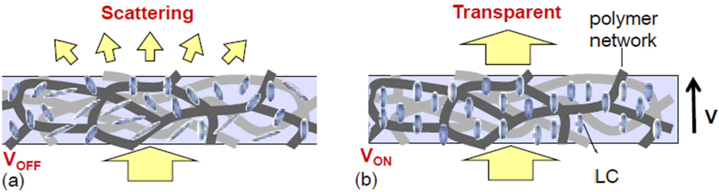
An extinction mechanism of the PLCF can be explained with
Figure 1. The molecules of liquid crystal and dichroic dye are surrounded by three-dimensional polymer networks that function as a chamber wall.
Figure 1a,b shows a cross-sectional film structure with no voltage and that with a voltage exceeding a threshold, respectively. It is assumed that the voltage is applied via transparent electrodes at the tops and bottoms. Without any voltages, the molecules are aligned randomly, forced by the polymer network shape. This results in light scattering when a light beam is incident from the bottom. In contrast, with the voltage higher than the threshold, the molecules are aligned in parallel to the electric field and, then, the incident light beam goes straight up toward the top. That is, the PLCF becomes transparent.
Test samples were prepared as follows: First, all the composite materials are mixed and stirred. The materials used are nematic mixture of E7 (Fuji Pigment, Hyogo, Japan) as liquid crystal material, monomer materials of 3,5,5-trimethylhexylacrylate (Aldrich, St. Louis, MO, USA) and 1,6-hexanedioldiacrylate (Aldrich) as photo-initiator, and dichroic dye. Fractions of the materials are approximately 80 and 20 weight percent for the liquid crystal and the monomer, respectively. The composite materials were injected into a 13-μm spacing glass cell. Transparent electrodes of indium tin oxide were coated on the inside of the two glasses. Finally, ultraviolet light was incident on the sample to form the three-dimensional polymer network.
Table 1 shows sample number, dopant, dye category, and absorption peak wavelength of the dichroic dyes (all from Mitsui Chemical, Tokyo, Japan). The dye quantity in the sample was between 0.1 and 1 weight percent.
Figure 1.
(a) Cross-sectional (polymer/liquid crystal) composite film (PLCF) with no voltage; (b) Cross-sectional PLCF with a voltage exceeding a threshold. Small bars are liquid crystal molecules.
Figure 1.
(a) Cross-sectional (polymer/liquid crystal) composite film (PLCF) with no voltage; (b) Cross-sectional PLCF with a voltage exceeding a threshold. Small bars are liquid crystal molecules.
Table 1.
Summary of the dichroic dyes.
Table 1.
Summary of the dichroic dyes.
| Dopant | Dye category | Absorption peak wavelength (μm) |
|---|
| SIR132 | Metal complex | 1.03 |
| SIR103 | Phtalocyanine derivative | 0.95 |
| M370 | Anthraquinone derivative | 0.52, 0.55 |
| M618 | Azo derivative | 0.53 |
3. Experimental Setup
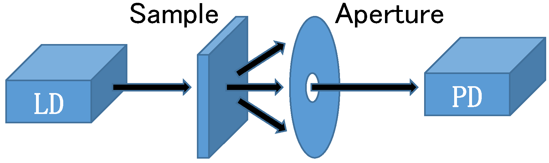
Light scattering is a key of our device; therefore, we have to configure a measurement setup to evaluate both transmission and scattering light. The employed light source is laser diodes (LDs) and an infrared He-Ne laser. The wavelengths we used are 0.532 or green, 0.635 or red, and 1.523 μm or infrared. All the lasers emit linearly polarized beam. The lights are incident on the photodiode (PD) through a sample and an aperture. The transmitted and scattering light is input to the 5-mm-diameter PD, while the fraction of the scattering light can be controlled by changing the aperture size.
We applied 1-kHz sinusoidal wave voltage to the sample; however, a voltage source is not shown in
Figure 2. Note that this setup does not require any polarization configurations.
Figure 2.
Measurement setup. LD: laser diode, PD: photodiode. A voltage source is not shown but is connected to the sample.
Figure 2.
Measurement setup. LD: laser diode, PD: photodiode. A voltage source is not shown but is connected to the sample.
4. Experimental Results
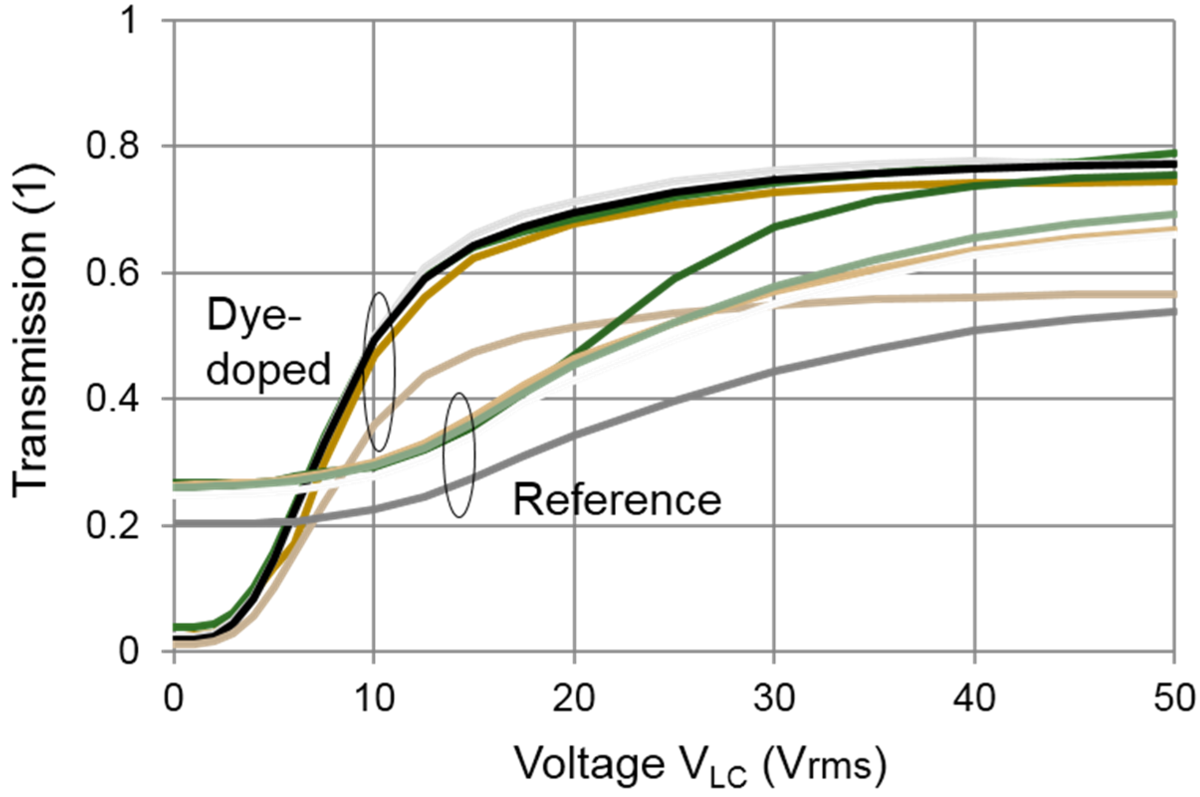
Transmission characteristics were measured at some wavelengths with a parameter of the aperture size or solid angle between the sample and the aperture. To avoid complexity, the results at 1.523 μm are shown in
Figure 3 only for the reference and SIR132 sample. For both samples, the transmission becomes larger as the applied voltage increases. When the samples were observed visibly, they were opaque at the voltage of 0 V but they became transparent at the voltage of 30 V or higher. The extinction ratios are about 3 and 51 for the reference and the SIR132 sample, respectively, when the ratio is evaluated at the smallest solid angle. Not shown in
Figure 3, the extinction ratios of SIR103 is 7.4 and that of other samples is about 3, which is close to the extinction ratio of the reference. It is experimentally shown that the extinction was improved by doping SIR132 and SIR103. Very little improvements were observed for M370 and M618. In
Figure 3, several lines are plotted for the different solid angle and this shows that the transmission becomes higher as the solid angle becomes larger.
Figure 3.
Transmission dependence on the applied voltage VLC. The curves are drawn for the solid angle of 0.025 (top), 0.018, 0.0063, 0.0031, 0.0020, 0.0016, 0.0008, and 0.0004 steradians (bottom). The wavelength was 1.523 μm. Dye-doped: SIR-132 doped, Reference: undoped.
Figure 3.
Transmission dependence on the applied voltage VLC. The curves are drawn for the solid angle of 0.025 (top), 0.018, 0.0063, 0.0031, 0.0020, 0.0016, 0.0008, and 0.0004 steradians (bottom). The wavelength was 1.523 μm. Dye-doped: SIR-132 doped, Reference: undoped.
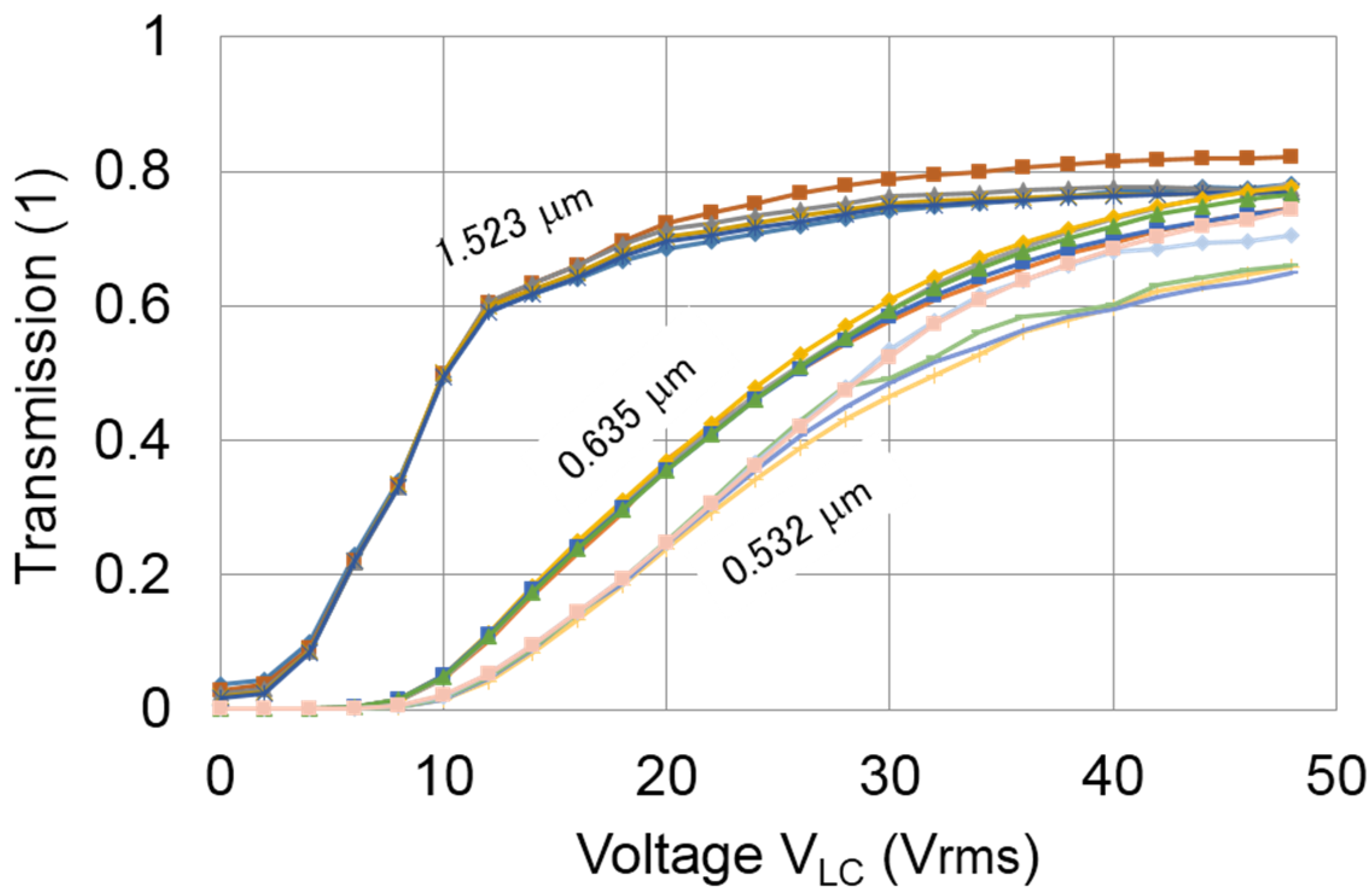
Figure 4 shows the transmission dependence on the voltage for the SIR132 at some wavelengths. As described, the SIR132 sample exhibits a good extinction from red to infrared although the transmission curves are somewhat different. All the transmission increase as the voltage increases. The voltage threshold is only about 2 V for 1.523 μm while it is about 10 V at 0.523 and 0.635 μm. These tendencies are the same as other samples. During the transmission measurements, we have not observed significant hysteresis effects in any samples.
Typical rise times were a few ms and fall times were a few to 10 ms; however, these were dependent on the applied voltages and on the dye dopants.
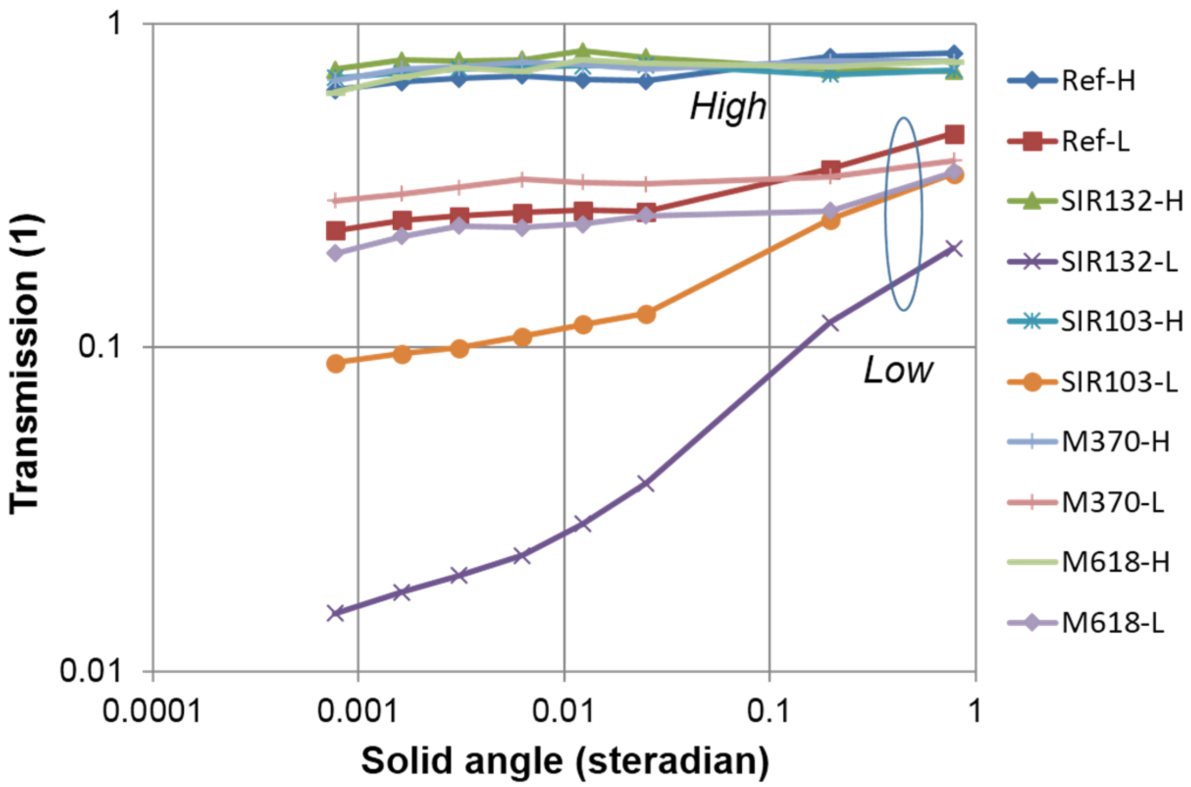
To distinguish the extinction mechanism, transmission and extinction ratio dependence on the solid angles is shown in
Figure 5 and
Figure 6, respectively. If the extinction mechanism is based only on the light absorption, the transmission and extinction ratio should be independent of the solid angle. If the extinction mechanism includes the light scattering, the transmission and extinction ratio should depend on the solid angle. In
Figure 5, high and H are the transmissions at 50 V and low and L the transmissions at 0 V. The high values are relatively flat even when the solid angle changes approximately 10
3 times. In addition, the high transmission is not strongly dependent on the dopants. On the other hand, the low transmissions increase as the solid angle becomes wider. The smallest low transmission was observed from the SIR132 sample and the second smallest form SIR103. The low transmissions of the M370 and M618 samples were not drastically reduced, even if the dichroic dyes were doped.
Figure 4.
Transmission dependence on the applied voltage VLC. The measurement was done at the solid angles between 7.9 × 10⁻⁵ (lowest) and 2.0 × 10⁻³ (highest) steradians and at the wavelengths of 0.532, 0.635, and 1.523 μm. Sample: SIR132.
Figure 4.
Transmission dependence on the applied voltage VLC. The measurement was done at the solid angles between 7.9 × 10⁻⁵ (lowest) and 2.0 × 10⁻³ (highest) steradians and at the wavelengths of 0.532, 0.635, and 1.523 μm. Sample: SIR132.
Figure 5.
Transmission dependence on the solid angle. High and H data were measured at 50 V and low and L data are measured at 0 V. Wavelength: 1.523 μm.
Figure 5.
Transmission dependence on the solid angle. High and H data were measured at 50 V and low and L data are measured at 0 V. Wavelength: 1.523 μm.
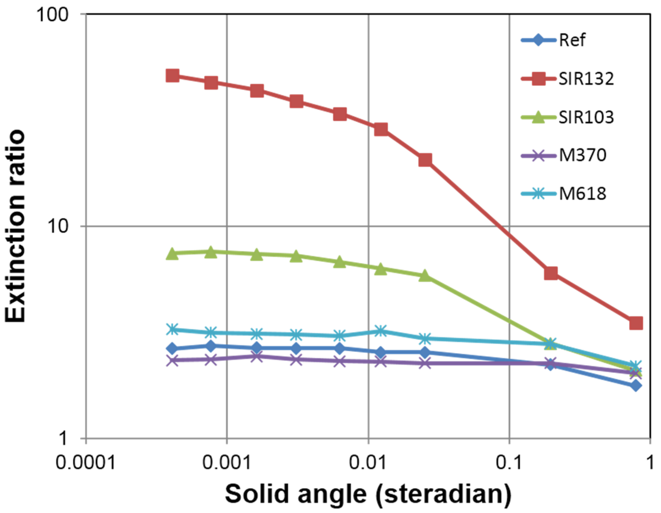
The ratio of high to low (extinction ratio) are calculated and shown in
Figure 6. The extinction ratio was mesured as 51 or 17.1 dB, the largest among the samples, for SIR132, and as 7.4 or 8.7 dB, the second largest, for SIR103. The extinction ratios decrease as the solid angle becomes wider for these two samples of SIR132 and SIR103. This fact suggests the extnction mechanism for these samples includes light scattering. In contrast, the extinction ratio does not strongly depend on the solid angle for the three samples of the reference, M370, and M618. The measured light intensity is a summation of the transmitted and scattered light and, then, quantitative fractions of asbsorption and scattering cannot be estimated for these results. Nevertheless, the light scattering is one of the strong candiate for the extinction mechanim of SIR132 and SIR103. These dopants are metal complex and phtalocyanine derivative, respectively.
Figure 6.
Extinction ratio dependence on the solid angle. Wavelength: 1.523 μm.
Figure 6.
Extinction ratio dependence on the solid angle. Wavelength: 1.523 μm.
5. Discussion
We discuss scattering details and polarization in this section. The former is to clarify the extinction mechanism in detail and the latter to evaluate performances as a VOA.
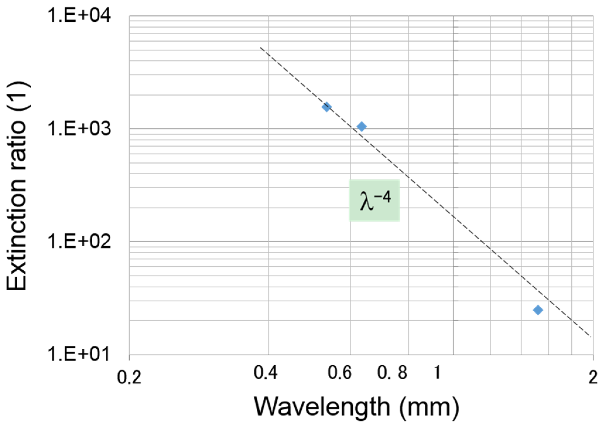
Scattering is usually characterized into Rayleigh and Mie scattering by a size of objects that disturb wave propagation [
12]. Rayleigh scattering occurs when the wavelength is even larger than the radius of the object. A Rayleigh-scattering light intensity is inversely proportional to the 4th power of the wavelength. We cannot completely distinguish the transmission and scattering light fraction, as described in
Section 4; however, the low transmission at 0 V may not include much fraction of the transmitted light.
Figure 7 shows the extinction ratio dependence on the wavelength. Due to the availability of LDs, the number of plot points is limited to three but the data points are clearly on the −4th power line. This suggests the extinction mechanism is related to the Rayleigh scattering. The Rayleigh scattering is one of the strong candidates for the explanation of extinction but further investigation is needed to make a judgment.
We have some data related to polymer structures. It is not easy to characterize the shape and size of a chamber, which is surrounded by the polymer chain, although the chamber shapes and sizes seem dependent on the dopants. This fact is directly connected to the scattering mechanism. We added dyes to enhance the extinction by the absorption but the dyes changed the chamber characteristics as well to affect the light scattering other than the absorption.
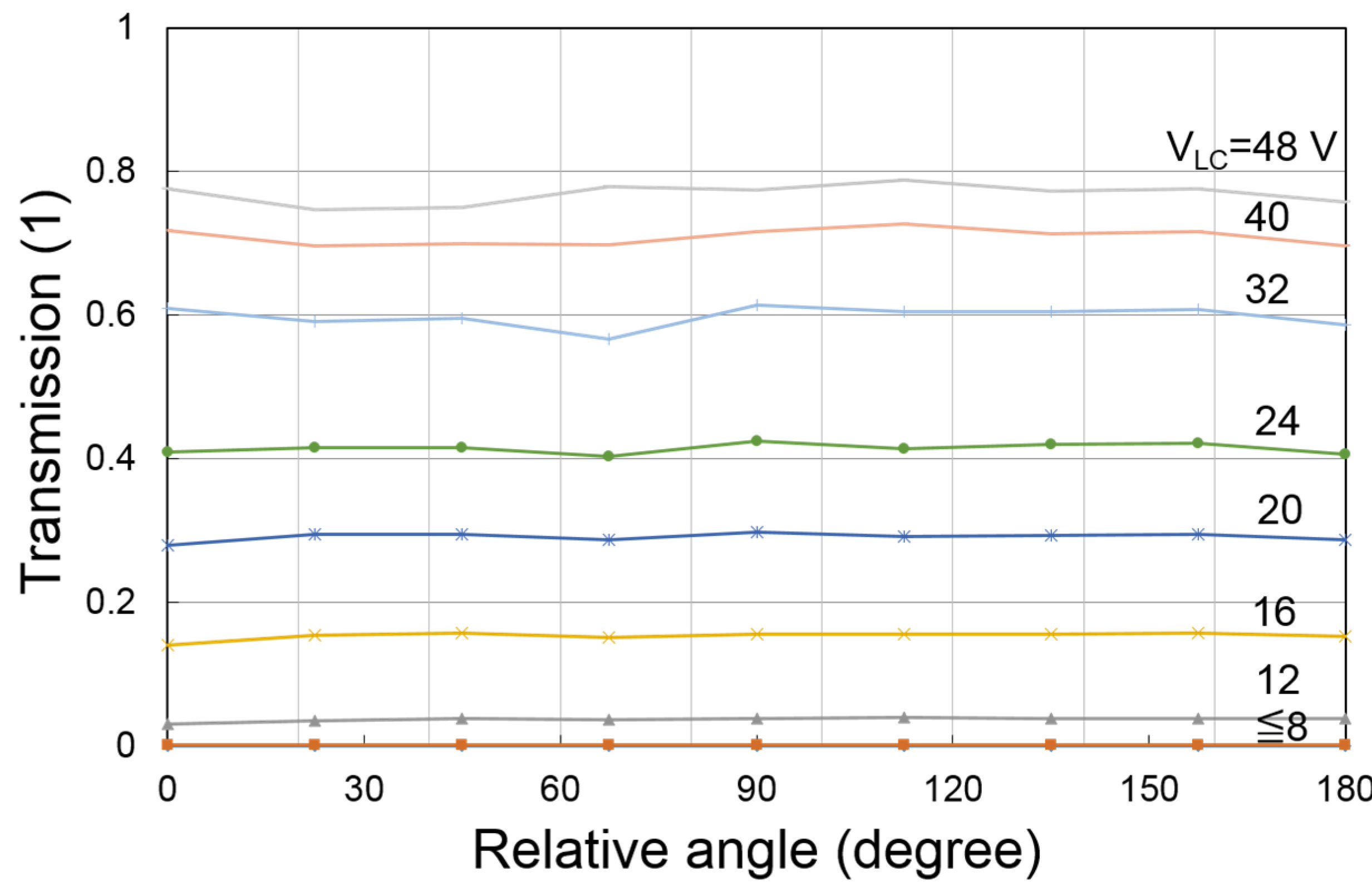
VOAs should not have a transmission dependence on the incident light polarization.
Figure 8 shows the 0.635-μm transmission dependence on the input light polarization. The PLCF does not have an absolute angle definition such as a rubbing angle so that the angle is a relative one. The sample was rotated in the same axis to the light propagation direction. The transmissions change only slightly for all the voltages between 0 and 48 V. The standard deviation of the transmission is lower than 0.1 dB for the LC voltage V
LC of 20 V or higher. The worst deviation we measured is 7.6% or 0.32 dB, which was observed at 8 V. The PDL is so small that it could be applied to the device in the telecommunication system.
Figure 7.
The extinction ratio dependence on the wavelength. Sample: SIR132.
Figure 7.
The extinction ratio dependence on the wavelength. Sample: SIR132.
Figure 8.
Transmission as a function of the relative angle. The sample was rotated at the experiment but this is equivalent to the light polarization rotation. Sample: SIR132.
Figure 8.
Transmission as a function of the relative angle. The sample was rotated at the experiment but this is equivalent to the light polarization rotation. Sample: SIR132.


