
High-Yield Synthesis of Helical Carbon Nanofibers Using Iron Oxide Fine Powder as a Catalyst

Abstract
:1. Introduction


| Role | Type of catalyst | Catalytic effect |
|---|---|---|
| Catalyst | Ni [7] | High ability of carbon segregation |
| Fe [19] | ||
| Co [20], Pd [21] | ||
| Promoter | Cu [10], Sn [19] | Low carbon segregation ability |
| S [22] | Synergetic effect with catalyst | |
| In [23] | Keeps the distance between catalyst nanoparticles | |
| K [24] | Controls the coil diameter |
2. Results and Discussion
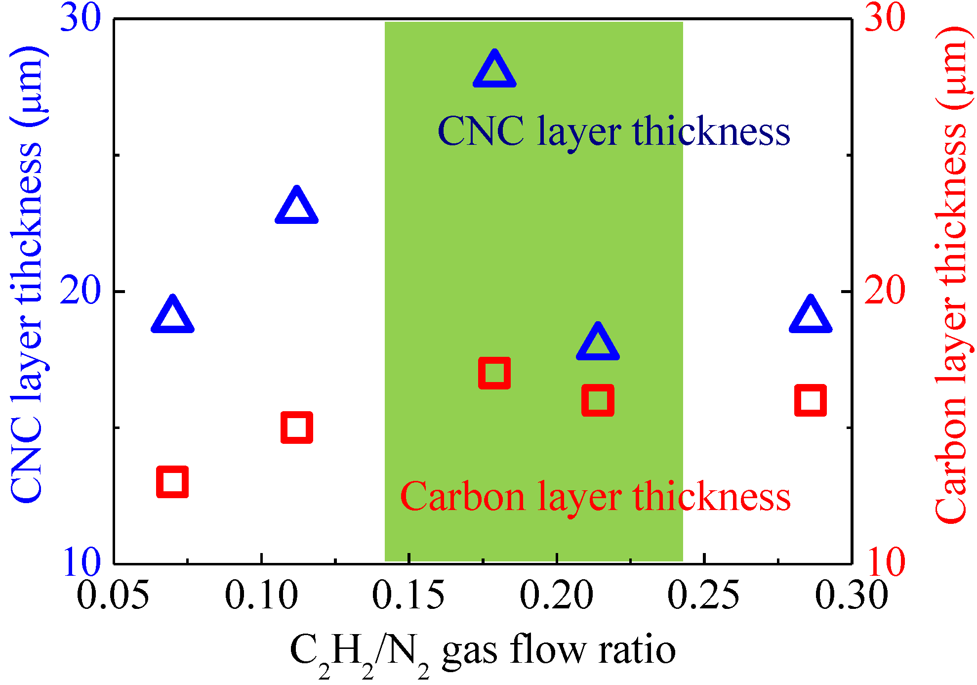
2.1. Effect of Gas Flow Rate
| Catalyst precursor | Fe2O3 fine powder (Diameter: 20 nm, Nilaco, Tokyo, Japan) SnO2 drop-coating solution (0.13 M, Kojundo Chemical Laboratory, Sakado, Japan) |
|---|---|
| Spin-coating velocity | 1000–2500 rpm |
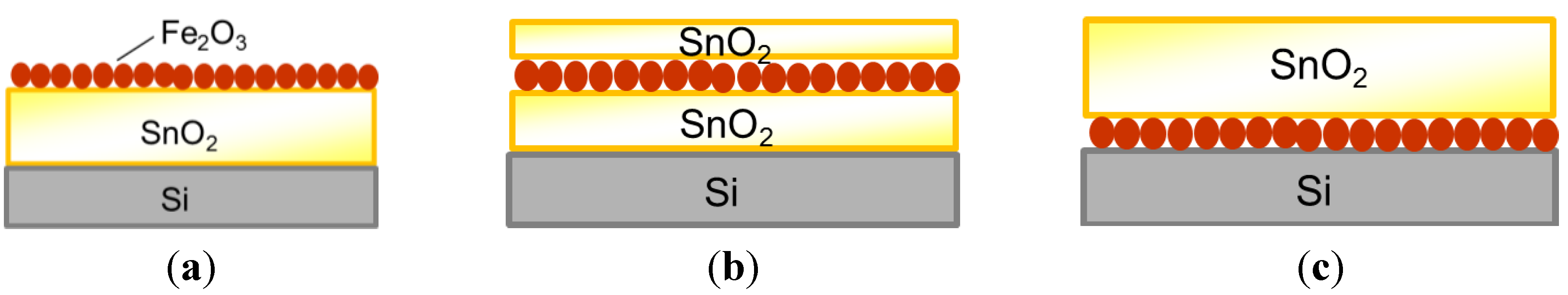
| Catalyst structure | Fe2O3/SnO2, SnO2/Fe2O3/SnO2, SnO2/Fe2O3 |
| Catalyst molar ratio | Fe:Sn = 1:2.6–1:13 |
| Feedstock gas (flow rate) | C2H2 (100–400 mL/min) |
| Dilution gas (flow rate) | N2 (1000–1800 mL/min) |
| Synthesis temperature | 780 °C |
| Synthesis time | 0.5–30 min |
| Annealing temperature | 780 °C |
| Annealing time | 5 min |

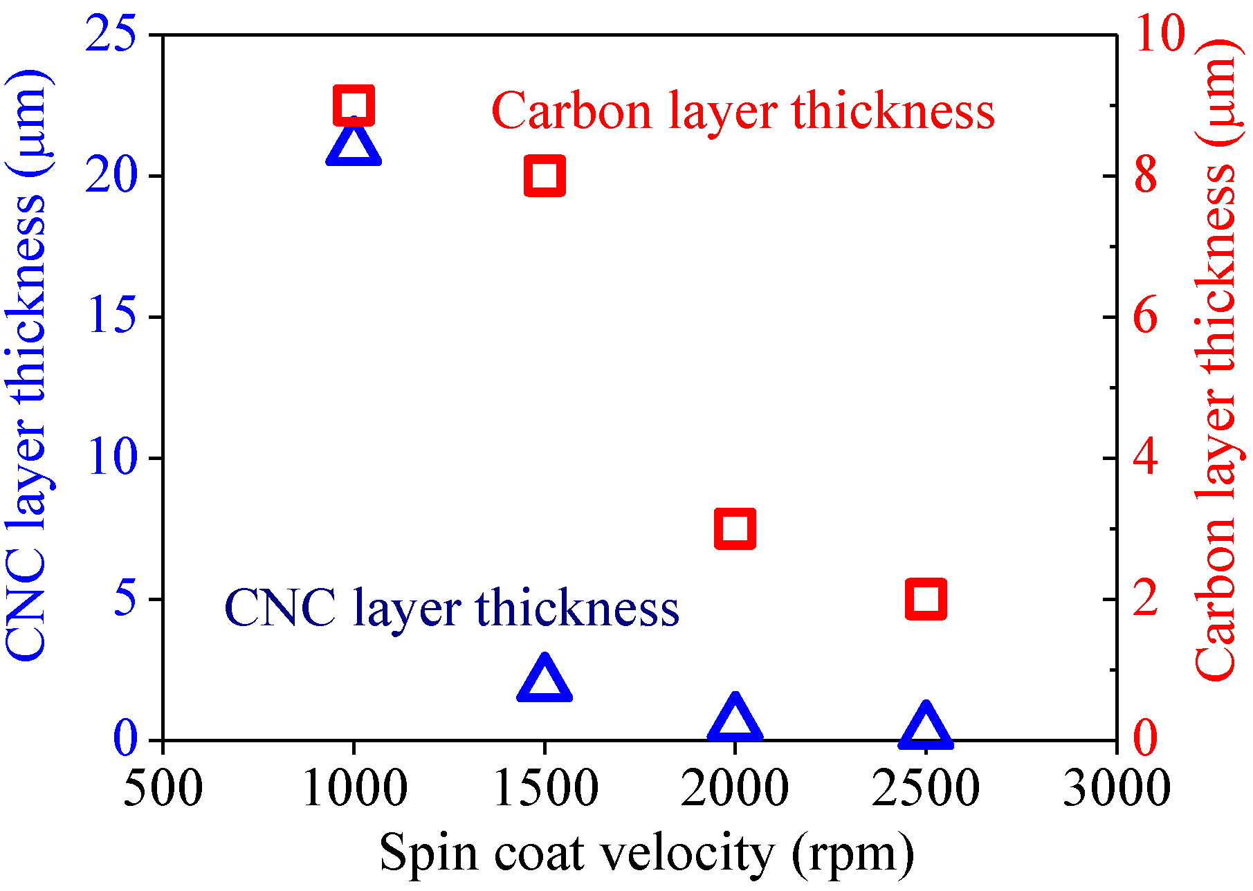
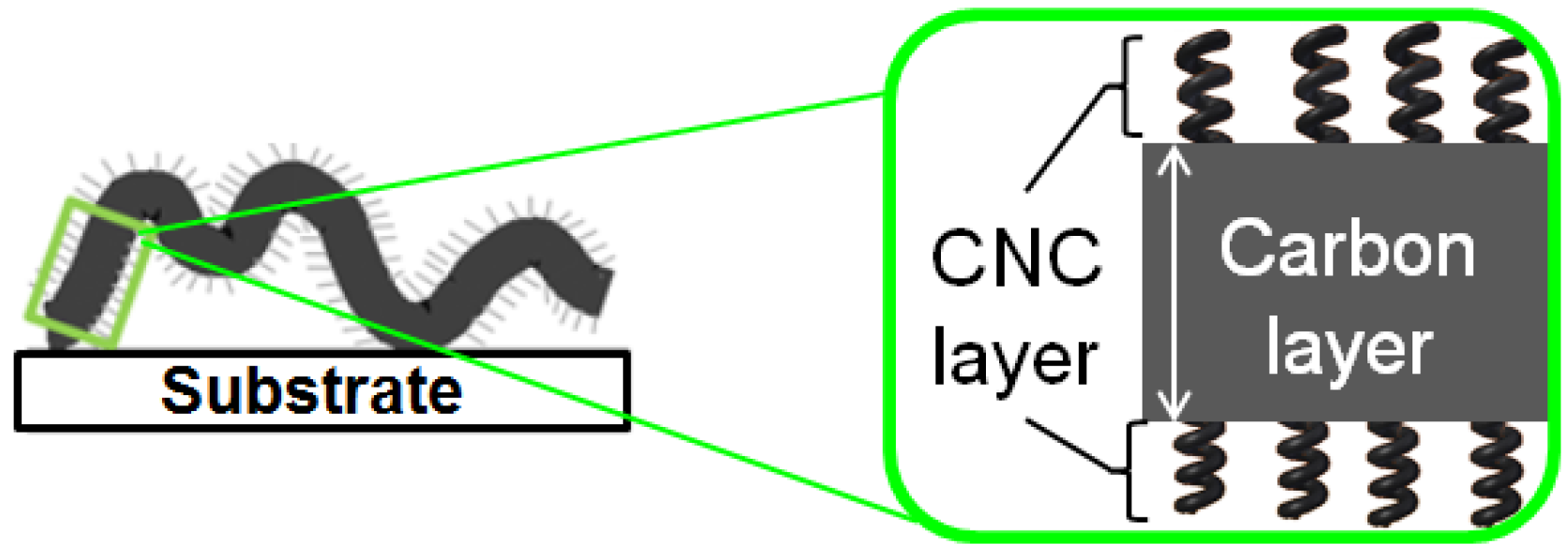
2.2. Effect of Spin-Coating Velocity and Synthesis Time


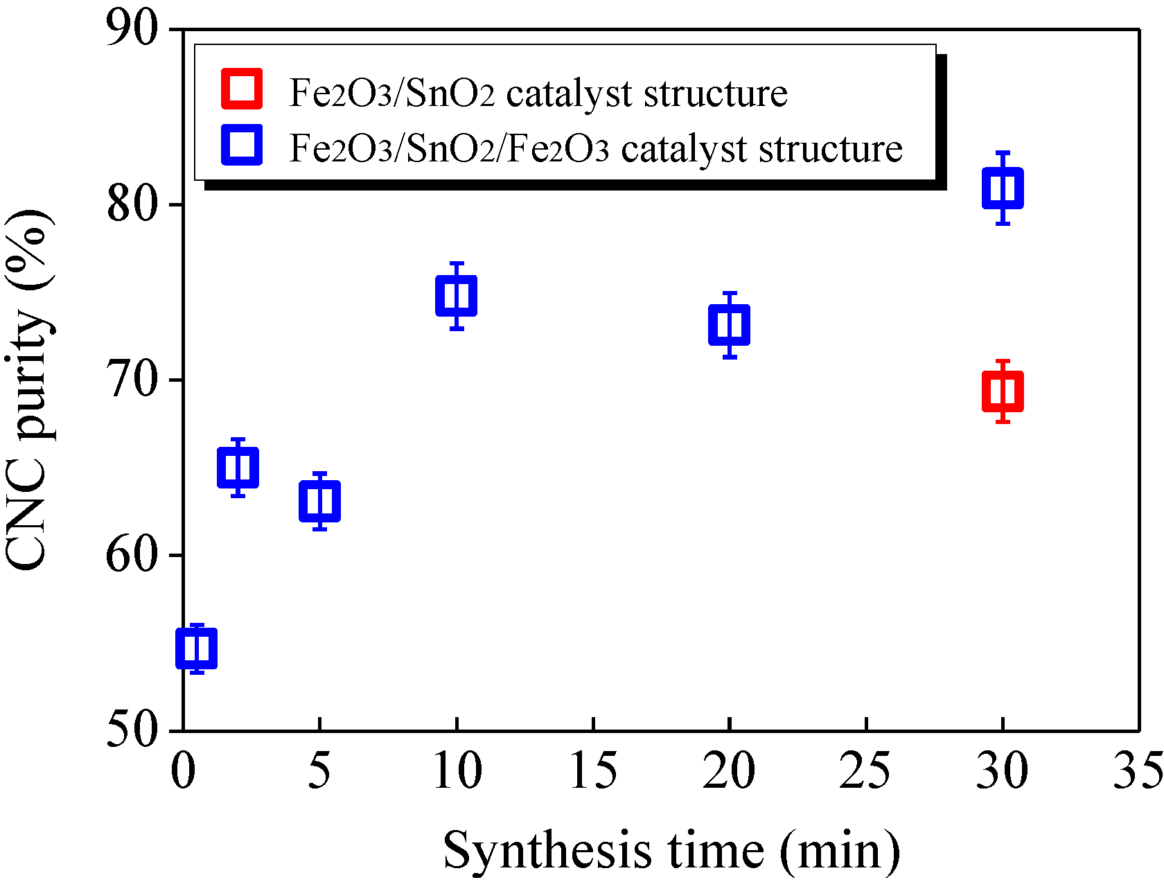
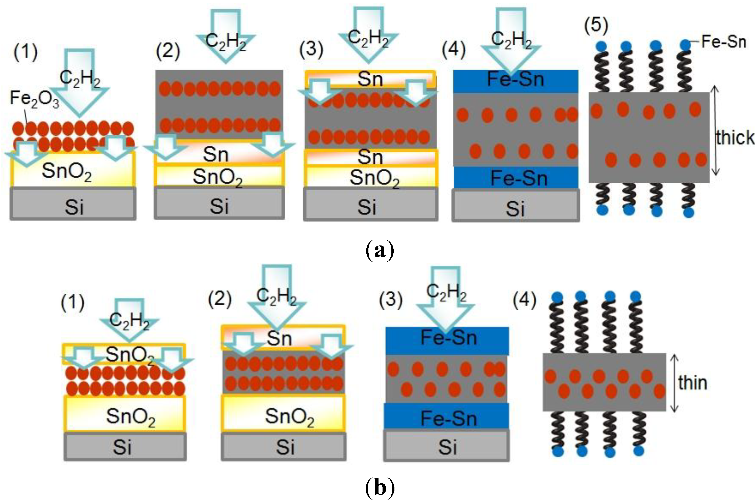
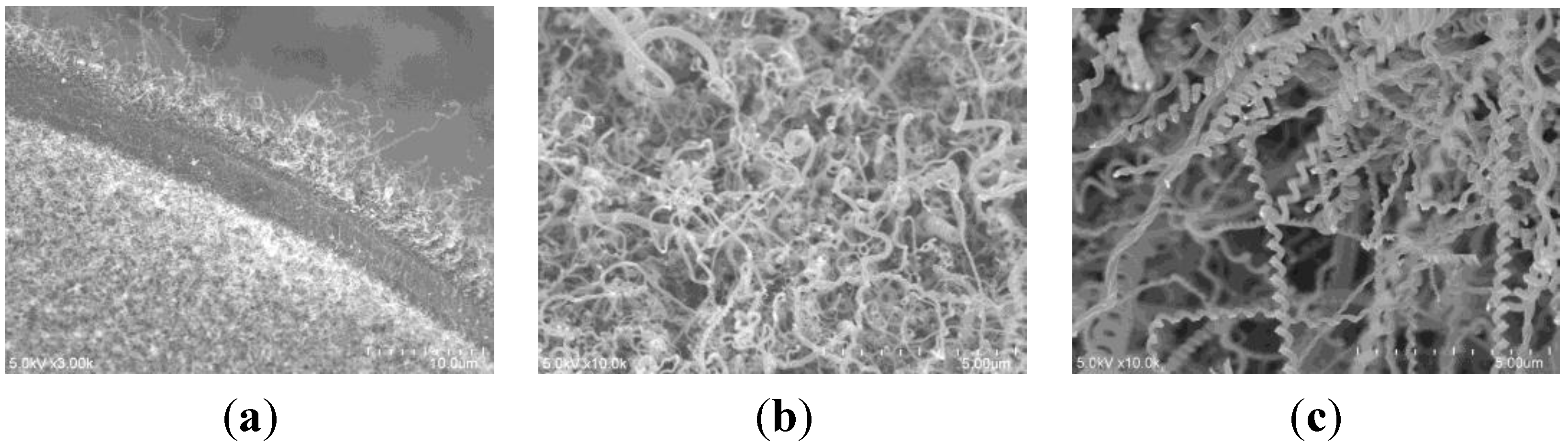
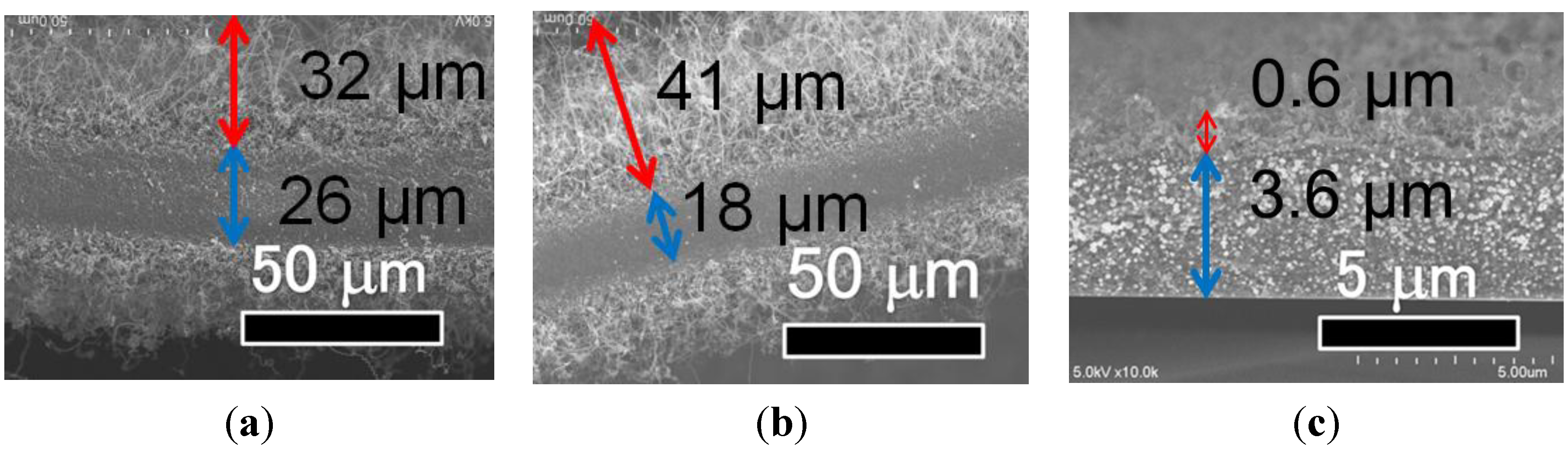
2.3. Effect of Catalyst Structure


3. Experimental Section
3.1. Evaluation Method

3.2. Catalyst Formation

3.3. CVD Conditions

4. Conclusions
Acknowledgments
Author Contributions
Conflicts of Interest
References
- Sugioka, Y.; Yokota, M.; Pude, T.; Suda, Y.; Takikawa, H.; Tanoue, H.; Ue, H.; Umeda, Y.; Shimizu, K. Effect of filament discharge on upright of carbon nanotwists tightly-adhered to substrate. Jpn. J. Appl. Phys. 2011, 50. [Google Scholar] [CrossRef]
- Kroto, H.W.; Health, J.R.; O’Brien, S.C.; Curl, R.F.; Smally, R.E. C60: Buckminsterfulleren. Nature 1985, 318, 162–163. [Google Scholar] [CrossRef]
- Iijima, S. Helical microtubules of graphitic carbon. Nature 1991, 354, 56–58. [Google Scholar] [CrossRef]
- Ihara, S.; Itoh, S. Helically coiled and toroidal cage forms of graphitic carbon. Carbon 1995, 33, 931–939. [Google Scholar] [CrossRef]
- Nishimura, K.; Kim, Y.A.; Matsushita, T.; Hayashi, T.; Endo, M. Structural characterization of boron-doped submicron vapor-grown carbon fibers and their anode performance. J. Mater. Res. 2000, 15, 1303–1313. [Google Scholar] [CrossRef]
- Motojima, S.; Kawaguchi, M.; Nozaki, K.; Iwanaga, H. Growth of regularly coiled carbon filaments by Ni catalyzed pyrolysis of acetylene, and their morphology and extension characteristics. Appl. Phys. Lett. 1990, 56, 321–323. [Google Scholar] [CrossRef]
- Motojima, S.; Chen, Q. Three-dimensional growth mechanism of cosmo-mimetic carbon microcoils obtained by chemical vapor deposition. J. Appl. Phys. 1999, 85, 3919–3921. [Google Scholar] [CrossRef]
- Zhang, M.; Nakayama, Y.; Pan, L. Synthesis of carbon tubule nanocoils in high yield using iron-coated indium tin oxide as catalyst. Jpn. J. Appl. Phys. 2000, 39, 1242–1244. [Google Scholar] [CrossRef]
- Pan, L.; Hayashida, T.; Harada, A.; Nakayama, Y. Effects of iron and indium tin oxide on the growth of carbon tubule nanocoils. Phys. B 2002, 323, 350–351. [Google Scholar] [CrossRef]
- Katsumata, T.; Fujimura, Y.; Nagayama, M.; Tabata, H.; Takikawa, H.; Hibi, Y.; Sakakibara, T.; Itoh, S. Synthesis of twisted carbon nanofiber by catalytic CVD method. Trans. Mater. Res. Soc. Jpn. 2004, 29, 501–504. [Google Scholar]
- Lu, M.; Liu, W.M.; Guo, X.Y.; Li, H.L. Coiled carbon nanotubes growth via reduced-pressure catalytic chemical vapor deposition. Carbon 2004, 42, 805–811. [Google Scholar] [CrossRef]
- Bajpai, V.; Dai, L.; Ohashi, T. Large-scale synthesis of perpendicularly aligned helical carbon nanotubes. J. Am. Chem. Soc. 2004, 126, 5070–5071. [Google Scholar] [CrossRef] [PubMed]
- Takikawa, H.; Yatsuki, M.; Miyano, R.; Nagayama, M.; Sakakibara, T.; Itoh, S.; Ando, Y. Amorphous carbon fibrilliform nanomaterials prepared by chemical vapor deposition. Jpn. J. Appl. Phys. 2000, 39, 5177–5179. [Google Scholar] [CrossRef]
- Mcllroy, D.N.; Zhang, D.; Kranov, Y.; Norton, M.G. Nanosprings. Appl. Phys. Lett. 2001, 79, 1540–1542. [Google Scholar] [CrossRef]
- Suda, Y.; Takikawa, H.; Tanoue, H. Syntheses and Electronic Applications of Helical Carbon Nanofibers. In Carbon Nanotubes/Book 2; INTECH: Rijeka, Croatia, 2011; pp. 37–70. [Google Scholar]
- Yang, S.; Chen, X.; Kikuchi, N.; Motojima, S. Catalytic effects of various metal carbides and Ti compounds for the growth of carbon nanocoils. Mater. Sci. 2008, 62, 1462–1465. [Google Scholar]
- Yokota, M.; Suda, Y.; Takikawa, H.; Ue, H.; Shimizu, K.; Umeda, Y. Structural analysis of multi-walled carbon nanocoils synthesized with Fe–Sn catalyst supported on zeolite. J. Nanosci. Nanotechnol. 2011, 11, 2344–2348. [Google Scholar] [CrossRef] [PubMed]
- Wang, G.; Ran, G.; Wan, G.; Yang, P.; Gao, Z.; Lin, S.; Fu, C.; Qin, Y. Size-Selective Catalytic Growth of Nearly 100% Pure Carbon Nanocoils with Copper Nanoparticles Produced by Atomic Layer Deposition. ACS Nano 2014, 8, 5330–5338. [Google Scholar] [CrossRef] [PubMed]
- Hirahara, K.; Nakayama, Y. The effect of a tin oxide buffer layer for the high yield synthesis of carbon nanocoils. Carbon 2013, 56, 264–270. [Google Scholar] [CrossRef]
- Sun, L.F.; Mao, J.M.; Pan, Z.W.; Chang, B.H.; Zhou, W.Y.; Wang, G.; Qian, L.X.; Xie, S.S. Growth of straight nanotubes with a cobalt-nickel catalyst by chemical vapor deposition. Appl. Phys. Lett. 1999, 74, 644–646. [Google Scholar] [CrossRef]
- Nitze, F.; Abou-Hamad, E.; Wagberg, T. Carbon nanotubes and helical carbon nanofibers grown by chemical vapour deposition on C60 fullerene supported Pd nanoparticles. Carbon 2011, 49, 1101–1107. [Google Scholar] [CrossRef]
- Wei, J.; Zhu, H.; Jia, Y.; Shu, Q.; Li, C.; Wang, K.; Wei, B.; Zhu, Y.; Wang, Z.; Luo, J.; et al. The effect of sulfur on the number of layers in a carbon nanotube. Carbon 2007, 45, 2152–2158. [Google Scholar] [CrossRef]
- Wang, W.; Yang, K.; Gaillard, J.; Bandaru, P.R.; Rao, A.M. Rational synthesis of helically coiled carbon nanowires and nanotubes through the use of tin and indium catalysts. Adv. Mater. 2008, 20, 179–182. [Google Scholar] [CrossRef]
- Tsou, T.Y.; Lee, C.Y.; Chiu, H.T. K and Au bicatalyst assisted growth of carbon nanocoils from acetylene: effect of deposition parameters on field emission properties. ACS Appl. Mater. Interfaces 2012, 4, 6505–6511. [Google Scholar] [CrossRef] [PubMed]
- Eguchi, U.; Takikawa, H.; Suda, Y. Electromagnetic wave absorption characteristics of multi-walled carbon nano-coils. Jpn. J. Appl. Phys. 2014, 53. [Google Scholar] [CrossRef]
- Wiliiams, K.L.; Köhler, J.; Boman, M. Fabrication and mechanical characterization of LCVD-deposited carbon micro-springs. Sens. Actuators A 2006, 130–131, 358–364. [Google Scholar] [CrossRef]
- Feng, C.; Liew, K.M. Structural stability of carbon nanosprings. Carbon 2011, 49, 4688–4694. [Google Scholar] [CrossRef]
- Yonemura, T.; Suda, Y.; Tanoue, H.; Takikawa, H.; Ue, H.; Shimizu, K.; Umeda, Y. Torsion fracture of carbon nanocoils. J. Appl. Phys. 2012, 112. [Google Scholar] [CrossRef]
- Lim, S.L.; Suda, Y.; Takimoto, K.; Ishii, Y.; Tanoue, H.; Takikawa, H.; Ue, H.; Shimizu, K.; Umeda, Y. Optimization of chemical vapor deposition for reducing the fiber diameter and number of graphene layers in multi-walled carbon nanocoils. Jpn. J. Appl. Phys. 2013, 52. [Google Scholar] [CrossRef]
- Yonemura, T.; Suda, Y.; Shima, H.; Tanoue, H.; Takikawa, H.; Ue, H.; Shimizu, K.; Umeda, Y. Real-time deformation of carbon nanocoils under axial loading. Carbon 2015, 83, 183–187. [Google Scholar] [CrossRef]
- Sevilla, M.; Sanchis, C.; Valdes-Solis, T.; Morallon, E.; Fuertes, A.B. Highly dispersed platinum nanoparticles on carbon nanocoils and their electrocatalytic performance for fuel cell reactions. Electrochim. Acta 2009, 54, 2234–2238. [Google Scholar] [CrossRef]
- Lim, S.L.; Takimoto, K.; Ishii, Y.; Suda, Y.; Tanoue, H.; Takikawa, H.; Ue, H.; Shimizu, K.; Umeda, Y. Improvement of growth yield of multi-walled carbon nanocoils by mesoporous materials and Sn amount. Trans. MRS Jpn. 2011, 36, 469–473. [Google Scholar]
- Suda, Y.; Ozaki, M.; Tanoue, H.; Takikawa, H.; Ue, H.; Shimizu, K.; Muramoto, H. Supporting PtRu catalysts on various types of carbon nanomaterials for fuel cell applications. J. Phys. 2013, 433. [Google Scholar] [CrossRef]
- Suda, Y.; Kaida, S.; Ozaki, M.; Shimizu, Y.; Okabe, Y.; Tanoue, H.; Takikawa, H.; Ue, H.; Shimizu, K. Use of carbon nanocoil as a catalyst support in direct methanol fuel cell. AIP Conf. Proc. 2014, 1585, 77–88. [Google Scholar]
- Pan, L.; Konishi, Y.; Tanaka, H.; Sueoka, O.; Nosaka, T.; Nakayama, Y. Effect of morphology on field emission properties of carbon nanocoils and carbon nanotubes. Jpn. J. Appl. Phys. 2005, 44, 1652–1654. [Google Scholar] [CrossRef]
- Hokushin, S.; Pan, L.; Konishi, Y.; Tanaka, H.; Nakayama, Y. Field emission properties and structural changes of a stand-alone carbon nanocoil. Jpn. J. Appl. Phys. 2007, 46, 565–567. [Google Scholar] [CrossRef]
- Hosokawa, Y.; Shinohara, Y.; Yokota, M.; Shiki, H.; Suda, Y.; Oke, S.; Takikawa, H.; Ina, T.; Morioki, M.; Fujimura, Y.; et al. Filament discharge enhances field emission properties by making twisted carbon nanofibres stand up. J. Phys. D 2008, 41. [Google Scholar] [CrossRef]
- Fujii, M.; Matsui, M.; Motojima, S.; Hishikawa, Y. Magnetoresistance in carbon micro-coils annealed at various temperatures. J. Cryst. Growth 2002, 237–239, 1937–1941. [Google Scholar] [CrossRef]
- Yamamoto, K.; Hirayama, T.; Kusunoki, M.; Yang, S.; Motojima, S. Electron holographic observation of micro-magnetic fields current-generated from single carbon coil. Ultramicroscopy 2006, 106, 314–319. [Google Scholar] [CrossRef] [PubMed]
- Katsuno, T.; Chen, X.; Yang, S.; Motojima, S.; Homma, M.; Maeno, T.; Konyo, M. Observation and analysis of percolation behavior in carbon microcoils/silicone-rubber composite sheets. Appl. Phys. Lett. 2006, 88. [Google Scholar] [CrossRef]
- Fujiyama, Y.; Tomokane, R.; Tanaka, K.; Akita, S.; Higashi, Y.; Pan, L.; Nosaka, T.; Nakayama, Y. Alignment of carbon nanocoils in polymer matrix using dielectrophoresis. Jpn. J. Appl. Phys. 2008, 47, 1991–1993. [Google Scholar] [CrossRef]
- Maruyama, K.; Suda, Y.; Tanoue, H.; Takikawa, H.; Ue, H.; Shimizu, K.; Umeda, Y. Improved mechanical properties of bucky paper achieved via the addition of carbon nanocoils. AIP Conf. Proc. 2014, 1585, 89–96. [Google Scholar]
- Xu, G.; Chen, B.; Shiki, H.; Katsumata, T.; Takikawa, H.; Sakakibara, T.; Itoh, S.; Ina, T. Parametric study on growth of carbon nanocoil by catalytic chemical vapor deposition. Jpn. J. Appl. Phys. 2005, 44, 1569–1576. [Google Scholar] [CrossRef]
- Suda, Y.; Ishii, Y.; Miki, T.; Maruyama, K.; Tanoue, H.; Takikawa, H.; Ue, H.; Shimizu, K.; Umeda, Y. Improvement of carbon nanocoil purity achieved by supplying catalyst molecules from the vapor phase in chemical vapor deposition. J. Mater. Res. 2014, 29, 2179–2187. [Google Scholar] [CrossRef]
- Yokota, M.; Shinohara, Y.; Kawabata, T.; Takimoto, K.; Suda, Y.; Oke, S.; Takikawa, H.; Fujimura, Y.; Yamaura, T.; Itoh, S.; et al. Splitting and flattening of helical carbon nanofibers by acid treatment. J. Nanosci. Nanotechnol. 2010, 10, 3910–3914. [Google Scholar] [CrossRef] [PubMed]
- Li, D.; Pan, L. Necessity of base fixation for helical growth of carbon nanocoils. J. Mater. Res. 2012, 27, 431–439. [Google Scholar] [CrossRef]
- Hosokawa, Y.; Shiki, H.; Shinohara, Y.; Yokota, M.; Takikawa, H.; Ina, T.; Okada, F.; Fujimura, Y.; Yamaura, T.; Itoh, S.; et al. Preparation of powdery carbon nanotwist and application to printed field emitter. Res. Lett. Mater. Sci. 2007, 2007. [Google Scholar] [CrossRef]
- Sugioka, Y.; Suda, Y.; Tanoue, H.; Takikawa, H.; Ue, H.; Shimizu, K.; Umeda, Y. Effects of dielectric barrier discharge treatment conditions on the uprightness of carbon nanofibers. IEEE Trans. Plasma Sci. 2012, 40, 1794–1800. [Google Scholar] [CrossRef]
© 2015 by the authors; licensee MDPI, Basel, Switzerland. This article is an open access article distributed under the terms and conditions of the Creative Commons Attribution license (http://creativecommons.org/licenses/by/4.0/).
Share and Cite
Suda, Y.; Maruyama, K.; Iida, T.; Takikawa, H.; Ue, H.; Shimizu, K.; Umeda, Y. High-Yield Synthesis of Helical Carbon Nanofibers Using Iron Oxide Fine Powder as a Catalyst. Crystals 2015, 5, 47-60. https://doi.org/10.3390/cryst5010047
Suda Y, Maruyama K, Iida T, Takikawa H, Ue H, Shimizu K, Umeda Y. High-Yield Synthesis of Helical Carbon Nanofibers Using Iron Oxide Fine Powder as a Catalyst. Crystals. 2015; 5(1):47-60. https://doi.org/10.3390/cryst5010047
Chicago/Turabian StyleSuda, Yoshiyuki, Koji Maruyama, Tetsuo Iida, Hirofumi Takikawa, Hitoshi Ue, Kazuki Shimizu, and Yoshito Umeda. 2015. "High-Yield Synthesis of Helical Carbon Nanofibers Using Iron Oxide Fine Powder as a Catalyst" Crystals 5, no. 1: 47-60. https://doi.org/10.3390/cryst5010047