
The Orbital Angular Momentum Modes Supporting Fibers Based on the Photonic Crystal Fiber Structure
by
 ,
,
Hu Zhang
1,2,* ,
,
Xiaoguang Zhang
1,
Hui Li
1,
Yifan Deng
1,
Lixia Xi
1,
Xianfeng Tang
1 and
Wenbo Zhang
1,3 1
State Key Laboratory of Information Photonics and Optical Communications, Beijing University of Posts and Telecommunications, Beijing 100876, China
2
School of Ethnic Minority Education, Beijing University of Posts and Telecommunications, Beijing 100876, China
3
School of Sciences, Beijing University of Posts and Telecommunications, Beijing 100876, China
*
Author to whom correspondence should be addressed.
Crystals 2017, 7(10), 286; https://doi.org/10.3390/cryst7100286
Submission received: 24 July 2017
/
Revised: 20 September 2017
/
Accepted: 20 September 2017
/
Published: 6 October 2017
Abstract
:The orbital angular momentum (OAM) of light can be another physical dimension that we exploit to make multiplexing in the spatial domain. The design of the OAM mode supporting fiber attracts many attentions in the field of the space division multiplexing (SDM) system. This paper reviews the recent progresses in photonic crystal fiber (PCF) supporting OAM modes, and summarizes why a PCF structure can be used to support stable OAM transmission modes. The emphasis is on the circular PCFs, which possess many excellent features of transmission performance, such as good-quality OAM modes, enough separation of the effective indices, low confinement loss, flat dispersion, a large effective area, and a low nonlinear coefficient. We also compare the transmission properties between the circular PCF and the ring core fiber, as well as the properties between the OAM EDFA based on circular PCF and the OAM EDFA based on the ring core fiber. At last, the challenges and prospects of OAM fibers based on the PCF structure are also discussed.
1. Introduction
The increase of transmission capacity is always the challenging and urgent task for optical fiber communications. Up to now, nearly all the physical dimensions of a lightwave, including wavelength, amplitude, phase, and polarization, have been substantially exploited to deal with the ever increasing capacity requirements of optical fiber communication links. The capacity of the current optical fiber communication systems has reached a so called “capacity crunch” of 100 Tbit/s, which is the capacity limit over C + L bands in the single mode fiber [1]. Space division multiplexing (SDM) is considered to be a most promising method to overcome this coming capacity crunch. Two major enabling technologies have been researched and developed for SDM implementation. One is SDM by use of multicore fibers [2,3], which inherently require complex fiber fabrication to keep an appropriate core spacing to reduce core-to-core coupling. The other one is mode division multiplexing (MDM) by use of multimode fibers, which needs orthogonality among different spatial modes to avoid intermodal crosstalk. There are several different kinds of orthogonal modal basis sets that are potential candidates for MDM systems. One such set is the linearly polarized (LP) mode, which is composed of different vector modes with different propagation constants. The other set is orbital angular momentum (OAM) mode [4,5,6,7], which is composed of the even and odd modes of the same vector mode with nearly the same propagation constants. The former MDM systems (using few-mode (6–12 modes) fibers) require large and a complex multi-input multi-output (MIMO) digital signal processing algorithm to cope with the strong mode coupling [8,9], while the latter MDM systems are considered to be MIMO-free systems because of the weak coupling between the orthogonal OAM modes [10,11,12,13]. The OAM mode supporting fibers can offer a large number of OAM transmission modes and hence correspond to a large number of independent MIMO-free transmission channels. The structure design of the OAM mode supporting fibers is currently a hot topic in the research of the OAM mode-based optical fiber communication system.
Optical OAM mode is described with its helical phase wavefront of exp(ilφ) (l is topological charge, φ is azimuthal angle) and its annular intensity distribution. In order to match the feature of annular intensity-distributed OAM modes, a rational choice of fiber structure is an annular index profile. Also, in order to avoid the near-degeneracy of the constituent vector modes coupling into the LP modes, for this kind of fiber the refractive index contrast between different adjacent vector modes should be larger than 10−4 [14]. Ring fibers with a high index ring core [15,16,17,18,19,20,21,22,23,24], in which the high index is realized by up-doping, have been proposed to meet the above requirements. Up to date, the ring fibers with a hollow core can support up to 9 orders of OAM modes (34 OAM modes) or 36 information bearing states [20]. However, this type of fiber has two shortcomings: one is the complex up-doping process corresponding to complex fiber fabrication and higher transmission loss; And the other is its relatively thin ring core area (for avoiding excitation of higher radial orders OAM modes), which will lead to the spin-orbit coupling effect, and hence a larger loss.
It is a good idea to support OAM modes by using the structure of the photonic crystal fiber (PCF) [25,26], because PCF can offer more flexible design structures to provide unique fiber properties such as controllable nonlinearity and confinement loss [27,28], tailorable chromatic dispersion [28,29], etc. The PCF-based OAM modes supporting fibers show a bright application prospect in MDM fiber communications. In this paper we will review the recent achievements in PCF-based OAM modes supporting fibers [30,31,32,33,34,35,36,37,38,39,40,41,42,43,44,45]. The concepts of OAM modes in fibers and the design requirements of OAM fibers are presented in Section 2. In Section 3 we will review in detail some influential structures of the PCF-based OAM modes supporting fibers and compare the properties of different OAM fibers and OAM EDFAs. We will also discuss challenges and prospects of these kinds of PCF-based OAM fibers in Section 4.
2. Design of Fibers Supporting OAM Modes
2.1. OAM Modes in Optical Fiber
Both OAM modes and LP modes in optical fibers can be considered as a superposition of vector mode bases. The difference is that LP modes are formed by the vector modes with different propagation constants in the weakly guiding fibers, while OAM modes are constituted by those vector modes with nearly the same propagation constants in the fibers. Therefore, OAM modes do not suffer from inter-modal dispersion caused by mode walk-off transmission [14]. OAM modes in fibers are denoted as OAMl,m, where l (l = ± 1, ± 2, ± 3, …) is the topological charge, and m is the radial order corresponding to the intensity profile of the mode in radial direction. Orbital angular momentum (OAM) and spin angular momentum (SAM) are two aspects of a light beam and can coexist in the same light beam. SAM is related to the rotation of the polarization vector, while OAM is related to the twist of the beam wavefront. The number of supported OAM modes includes all degrees of degeneracies in polarization and in the direction of twist of phase front of the electric fields. OAM modes in fibers can be composed of vector eigenmodes by the following relations:
where the sign in superscript “±” denotes the right or left circular polarization corresponding to two values of SAM, and the sign in subscript “±l” denotes the right or left rotation direction of the wavefront of the OAM modes. The distinction between odd and even HE modes is π/2 azimuthal rotation in polarization, and is the same for odd and even EH modes; j presents a π/2 phase shift. The two modes composed by the fundamental HE1,m modes with left or right circular polarization cannot be considered as OAM mode for they carry no OAM [20]. Moreover, the two modes possessing opposite directions of polarization and wavefront rotation are actually composed by azimuthally polarized TE0,m and radially polarized TM0,m, which can also not be viewed as OAM modes because they have different propagation constants and are unstable in the fiber [14]. The OAM1,m with the identical directions of polarization and wavefront rotation, which is composed by even and odd HE2,1, has two OAM modes. The OAM modes with the same l and m compose an OAM mode family. When l = 1, the OAM family has 2 OAM states, and when l > 1, the OAM families include 4 OAM states.
2.2 Design Requirements of OAM Fibers
The design of one kind of OAM fiber is guided by many considerations under which we will ask what good features we can achieve. Many considerations are contrary to each other. So trade-off is an effective method during fiber design. The following factors should be considered in designing an OAM fiber.
(1) The index profile of the designed OAM fiber should match the intensity profile of OAM modes: An OAM beam spirals around the propagation axis and forms a ring intensity profile. In order to hold the ring-shaped OAM modes, rationally, the OAM fibers should have a circular or ring-shaped structure, in which the ring core area is with higher refractive index and inner hole, and the outer cladding is with lower indices. The ring fiber with step-index profile is a rational good design which can support 34 OAM modes [20]. The circular-shaped PCF is another rational design whose structure has a ring area (higher index area) surrounding several air-hole arrays (lower index area in average). Also, inside the high index area there should be a central air hole with lower index.
(2) For adjacent vector modes, large effective index separation (>10−4) between them should be achieved: The OAM mode transmission instability in the OAM fibers arises for the reason that the near degeneracy of the constituent HE and EH vector modes (in the same OAM family) easily leads to a result of being coupled into LP modes. To avoid this negative effect of stable transmission, the effective indices of the constituent HE and EH vector modes should be separated as much as possible, which will break the weakly guiding approximation condition. The general rule to keep OAM modes transmission stability is Δneff > 10−4, which comes from the polarization-maintaining fibers [14]. The high refractive index contrast requires the large material refractive index difference between the fiber core and the fiber cladding, which is easier to implement for the photonic crystal fiber than the ring fiber with up-doping. The thickness of the ring core can also influence the effective index separation. The larger the thickness is, the smaller the effective index separation is [45].
(3) OAM modes (as many as possible) can be supported in the designed OAM fiber: OAM modes belong to orthogonal eigenstates of Helmholtz equation, and the number of these orthogonal eigenstates is theoretically infinite. But the fiber can only support the limited number of OAM modes because of the restriction of the fiber structure. The number of OAM modes which can be stably transmitted in the fiber is decided by two factors. One is the radius of the fiber core, as we know that the number of mode increases with the increasing of fiber core radius. Another one is the degree of separation of mode-effective indices between adjacent vector modes in the same OAM mode family.
(4) Ensure all the guided OAM modes are good quality modes and avoid exciting the higher radial orders (m > 1) modes: Higher radial orders modes have more than one ring of intensity distribution, and the phase distributions at the different area sections of different rings are quite different, which would cause trouble to multiplex and demultiplex OAM modes. Therefore, exciting higher radial orders modes (m > 1) should be prevented in the designed fiber. For the ring fiber, thin thickness of high index ring core helps preventing excitation of higher radial orders modes. But large thickness of the ring core is the insurance of good mode quality for the transmitted OAM modes held in the ring core area. Moreover, the thin ring core structure is easy to cause spin-orbital coupling due to imperfect circular symmetry [7]. Considering the trade-off among mode quality, higher radial orders modes excited, and spin-orbital coupling, we should optimize the thickness of the ring core in designing the OAM fibers.
(5) The OAM modes excited in the designed OAM fibers would possess good transmission features such as low confinement loss, flat dispersion, large effective mode area, and low nonlinear coefficient within a larger wavelength range (at least covering C + L bands). Low confinement loss ensures longer transmission distance. Flat chromatic dispersion (CD) makes unified CD compensation possible at the receiver in wavelength division multiplexing (WDM). Large effective area and low nonlinear coefficient can limit the nonlinear signal distortion.
3. Review of OAM Fibers Based on Photonic Crystal Fiber Structure
As mentioned above, in order to match the ring-shaped intensity distribution of OAM modes, a direct, rationally designed OAM fiber is ring-shaped fiber. The ring fiber with a hollow center was so successful at supporting 34 OAM modes [20] that the “ring fiber” is nearly the substitution name of the OAM fiber over a period of time. The ring-shaped erbium-doped method was also used to design OAM modes amplifier. However, the design limits of ring-shaped OAM fibers are obvious: the reason is that the adjustable parameters are limited (for ring-shaped fiber, the parameters include the inner and outer radii, the indices of ring core, and cladding). This kind of limited optimization parameters can make us in a dilemma. For example, in order to prevent higher radial orders modes from exciting, we have to limit the thickness of the ring core, but in the meanwhile thin ring core area cannot offer enough area to form the good-quality OAM modes.
The photonic crystal fiber (PCF) structure can offer more degrees of freedom or more adjustable parameters for fiber optimization. PCFs are originally designed to get controllable transmission properties in fibers, such as flatten CD, low or high nonlinear coefficient, etc. Recently, PCFs were adopted to transmit OAM modes to fulfill the above requirements. The obvious advantage over the conventional ring-shaped OAM fibers is its more adjustable parameters for optimization to ensure good transmission quality of OAM modes. Another merit of PCF-based OAM fibers is that they can obtain high refractive index contrast between the ring core and the cladding region without any up-doping. The reported typical PCF structure-based OAM fibers can be divided into the following three categories according to the cladding structure.
3.1. Hexagonal Lattice PCFs
The first PCF structure reported for the transmission of OAM modes is an As2S3 ring PCF with hexagonal lattice cladding and a hollow center, as shown in Figure 1a, which can only support a lower number of OAM modes (2 OAM modes) with unsatisfied mode quality [30]. The values of the structure parameters Λ, r0, r2, and r3 (r3 = r4 = r5 = r6 = r7 = r8) are 0.4 μm, 0.18 μm, 0.12 μm, and 0.18 μm, respectively. This fiber is proposed to mimic the ring shape of the OAM modes as the ring fiber does, but the hexagonal structure of air-hole arrays is not a good design. The hexagonal structure cannot provide enough circular symmetry, which results in its poor OAM mode quality and higher confinement loss. However, the large nonlinear coefficient and relatively wider bandwidth (522 nm) of the fiber can be used to generate the supercontinuum.
Almost at the same time, the helically twisted PCF is proposed, as shown in Figure 1b, in which a regular hexagonal lattice of hollow holes is arrayed symmetrically as the fiber cladding around a central glass core [31,32,33,34]. This type of microstructure fiber is continuously twisted to match (mimic) the spiral properties of OAM, in which a fraction of the axial momentum is transformed into azimuthal momentum to form the OAM states. However, the fiber with the parameters of Λ ≈ 2.9 μm and d ≈ 0.9 μm can only support single OAM mode and has a high transmission loss. To increase the number of OAM modes and effective index separation between adjacent eigenmodes, the twisted air-core PCF is proposed [35]. This fiber enlarges the index contrast between the ring core and cladding to separate the OAM modes. Also, with the increase of the twist rate, the index separation of different OAM modes increases, but at the cost of losing high order modes.
Another PCF with hexagonal lattice is a 7-cell hollow-core photonic bandgap fiber (HC-PBGF), as illustrated in Figure 1c, which can confine the light into the low refractive index hollow core by the effect of photonic bandgap [41]. The optical field shape of the fiber shows six-fold symmetry, not circular symmetry. This fiber with the parameters of Λ= 4.7 μm, d = 0.98Λ, dh = 0.44Λ, tc = 0.01Λ, dc = 0.94Λ, and dr = 0.2Λ supports eight eigenmodes which can be used to constituted OAM modes by Equations (1) and (2) in theory, but only two OAM modes (OAM1,1) can propagate over long distance because of the high confinement loss for the high order modes.
3.2 Circular PCFs
The PCFs with hexagonal lattice can only hold a lower number of OAM modes with unsatisfied mode quality. Obviously, the photonic crystal structure with somewhat circular symmetry will help to support a higher number of good quality OAM modes. Based on this kind of idea, a circular type PCF was firstly proposed by our research group as shown in Figure 2 [36]. This kind of circular PCF, by optimizing design, can support 14, 26, and 42 good quality OAM modes with satisfied transmission properties like low confinement loss, flat CD, large effective mode area, and low nonlinear coefficient [39,42,43,45].
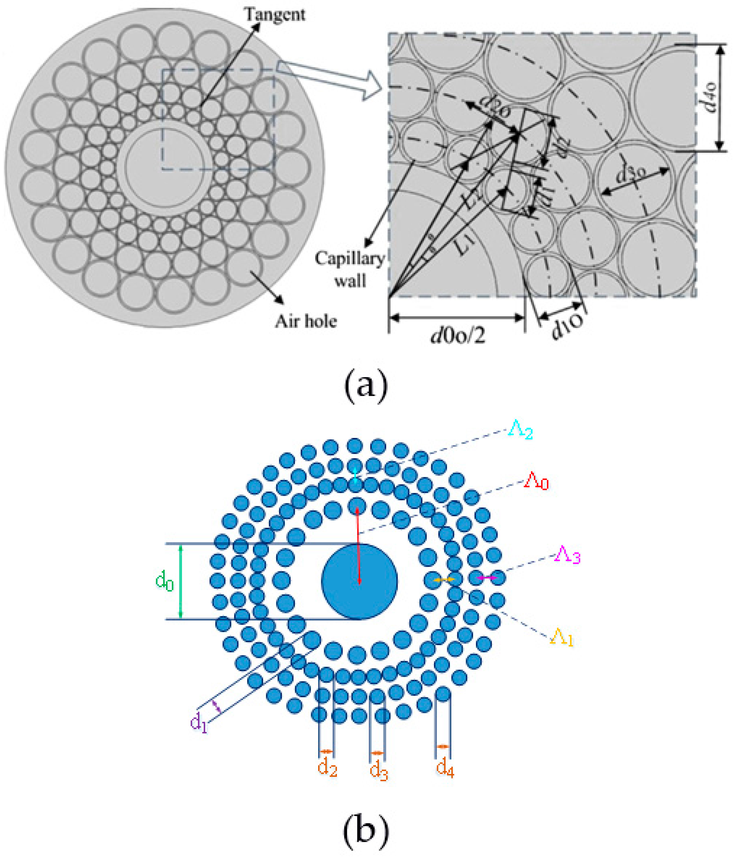
Before discussing the above-proposed circular PCF in detail, other PCF structures based OAM fibers should be pointed out. A microstructure ring fiber (MRF) with the same number of air holes in three different rings was presented to satisfy circular symmetry of the OAM optical intensity, as shown in Figure 3a [37,38]. Strictly speaking, this kind of optical fiber belongs to the microstructure fiber rather than PCF. The reason is that the cladding of the fiber is not a periodical structure. The air hole size of this kind of fiber is different in every ring but adjacent air holes keep tangent, and such a structure makes it easier to fabricate the preform. Also, the thick ring design can balance the mode separation, the coupling of SAM and OAM, as well as suppressing of the higher radial orders modes. But the MRF has narrow bandwidth and higher confinement loss.
Another type of circular PCF with the parameters of d0 = 6.6 μm, d1 = 1.8 μm, d2 = d3 = d4 = 1.2 μm, Λ0 = 6 μm, Λ1 = 1.8 μm, Λ2 = 1.5 μm, and Λ3 = 1.5 μm was also presented to adopt the similar fiber structure to that of MRF mentioned above, as shown in Figure 3b. In order to make the complete circular symmetry structure, the outer three rings of air holes are the same size but different gaps, while the size of the innermost ring of air holes is larger than that of other three rings. The base material of the fiber is As2S3 glass [40]. The outcome of this fiber design is only to increase the number of OAM modes based on the PCF structure in Ref. [30]. However, this kind of fiber is not suitable for the OAM mode transmission because of the high nonlinearity, while it is suitable for supercontinuum generation and short distance application. Furthermore, the fabrication of the fiber is difficult because of the complicated cladding structure.
Now, to get back to the circular PCF proposed by our research group. As shown in Figure 4, the circular photonic crystal fiber (C-PCF) has a big air hole in the center and several rings air-hole arrays around it as the fiber cladding, in between a ring-shaped area of base pure silica remains where OAM modes can be transmitted. Roughly speaking, the region occupied by pure silica contributes to refractive index with the value 1.444, and the region occupied by air holes provides index with the value of 1; therefore, the average refractive index of cladding area is the mean value of two regions weighted with the areas they occupy. Hence, the larger the air filling fraction is, the higher the index contrast between the OAM mode transmission area and the cladding area is. The discrepancy between the structure we proposed and MRF shown in Figure 3a is that the fiber design we proposed possesses the same size of the air holes and the same gaps between adjacent holes in the same ring and different rings, which maintains the periodical structure of PCF.
Actually, the circular PCF structure we proposed is the design which can construct an OAM fiber family. This fiber family consists of C-PCF 1#, C-PCF 2#, and C-PCF 3#, in which C-PCF n# fiber is constructed by removing off the first nth air-hole ring of the base fiber (for example, C-PCF 1# corresponds to removing off the first one air-hole ring) and putting a central air hole at the center, as shown in Figure 4b–d. We use a full-vector finite element mode solver (COMSOL) with a perfectly matched layer (PML) as boundary condition to calculate the properties of the mode in the PCFs. We can see that, by design optimization, all 5 requirements mentioned in Section 2.2 are fulfilled.
To analyze the properties of the fiber, we introduce two-dimension parameters similar to the definition in Ref. [19], effective normalized frequency Veff, and inner and outer radius ratio ρ, as follows
where λ is the wavelength in vacuum, nco is the index of the fiber core, ncl is the average effective index of the cladding, , and f is the air filling fraction of the cladding, which is defined as
where, f means the ratio of air hole area versus the total area in cladding. Roughly speaking, Veff determines the number of vector modes supported in the fiber; f makes an influence on ncl, and hence the index contrast; and ρ means the thickness of the ring area which hold the OAM modes, and hence determines the quality of the OAM modes held in the fiber.
We make the comparison between the C-PCF 1# and the ring core fiber in Ref. [19]. We can clearly see that for ring core fiber the cutoff frequency lines for high radial orders modes covers a higher value of ρ, which means a thinner ring area, as shown in Figure 5a. For example, at the Veff = 9.8, HE1,2 mode will cutoff when ρ > 0.65. However, the cutoff frequency lines for high radial orders modes show a flatter tendency, which means these cutoff lines cover less range of ρ, as shown in Figure 5b. For example, in the range of Veff < 12, HE1,2 mode will cutoff when ρ > 0.38. We conclude that compared with the ring core fiber, the designed C-PCF can support more OAM modes without exciting high radial orders (m > 2) modes, which is one of the advantages of the C-PCFs over the ring core fibers. Another advantage is that the smaller value of ρ (the thicker ring area) can be chosen to suppress the coupling between SAM and OAM while keeping more OAM modes during the process of the fiber design.
Based on 5 requirements mentioned above, which are essential for stable OAM mode transmission in long distance MDM systems, C-PCF 3# can support up to 42 OAM modes with good transmission features [45], such as good mode field quality, large index separation and flat dispersion over wide bandwidth, low confinement loss, and a low nonlinear coefficient. It is an effective method to increase the number of the OAM modes by changing inner air-hole arrays into ring core area, and hence enlarging the radius of ring area r, by which we also designed C-PCF 1# and C-PCF 2# in the OAM fiber family with different outer ring size, as shown in Table 1. The C-PCF 1# has the minimum number of mode and the maximum bandwidth, while C-PCF 3# has the maximum number of mode and the minimum bandwidth among the three fibers, as shown in Table 1. Three C-PCFs all cover entire band of optical fiber communications.
We also compare the transmission properties of the HE4,1 mode for three C-PCFs [45], in which we can find that C-PCF 3# has the best performance features such as dispersion value, dispersion variation ΔD in C band, confinement loss, and nonlinear coefficient. From C-PCF 1# to C-PCF 3#, the higher the number of air-hole rings that are removed, the lower the values of dispersion, confinement loss, and nonlinear coefficient are, and the greater flatness of the dispersion over wavelength range is. The main reason is the fact that the higher the number of air-hole rings removed means the larger the ring area that is required to hold the transmitted OAM modes in this region, and hence there is less chance for mode energy leakage; and also larger effective mode area corresponds to smaller nonlinear coefficient. Therefore, C-PCF 3# may be the best choice among the three.
Then, we make the comparison of transmission properties between the C-PCF 3# [45] and the ring core fiber [20]. The C-PCF 3# can support a greater number of OAM modes (42 modes) than the ring core fiber can (26 OAM modes in simulation, 34 OAM modes in experiment), and the bandwidth of the former is wider than that of the latter. At 1.55 µm, the minimum index separations of the C-PCF 3# and the ring core fiber are 2.7 × 10⁻⁴ (between HE11,1 and EH9,1) and 1.1 × 10⁻⁴ (between TE0,1 and HE1,1), respectively. The dispersion value and dispersion variation (equivalent to dispersion slope) of the C-PCF 3# in C band are larger than that of the ring core fiber, as shown in Figure 6. For example, at 1.55 µm, the ring core fiber shows a lower dispersion of 1.86 ps/(km.nm) for HE2,1 mode, while the C-PCF 3# shows a higher dispersion of 77.02 ps/(km.nm) for the same mode. The dispersion variations of HE8,1 mode in C band are 0.7 ps/(km.nm) for the ring core fiber, and 2.7 ps/(km.nm) for the C-PCF 3#, respectively. In addition, the ring core fiber with the high index contrast is fabricated by up-doping, while the C-PCF 3# is fabricated by single material of silica.
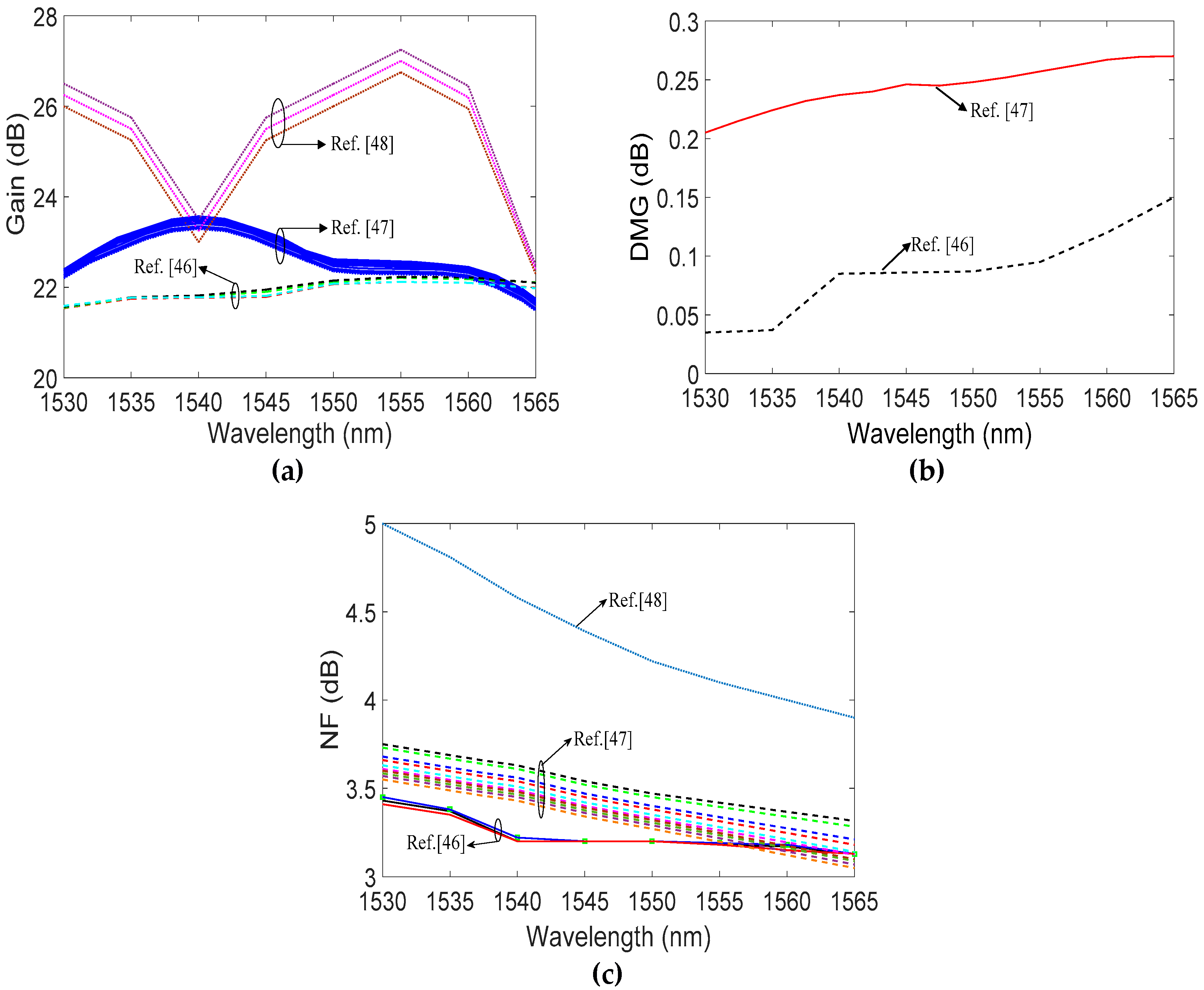
In addition, we also designed a core-pumped OAM erbium doped fiber amplifier (EDFA) based on C-PCF [46]; the proposed OAM fiber amplifier can provide a gain larger than 20 dB for all 14 OAM modes, with the small differential mode gain (DMG) less than 0.15 dB and the noise figure lower than 3.5 dB across the C-band (Ref. [46] in Figure 7). For the ring core fiber structure, the two-layer Erbium doping OAM EDFA using core pumped based on solid-core ring fiber can provide gain over 20 dB with DMG below 0.28 dB for all 18 OAM modes, and the noise figure larger than 3 dB over the C-band (Ref. [47] in Figure 7) [47]. The cladding-pumped OAM EDFA based on air-core ring fiber supports 12 OAM modes, with a gain more than 20 dB, DMG larger than 0.25 dB, and the noise figure larger than 3 dB over the C-band (Ref. [48] in Figure 7) [48]. Among three OAM EDFA structures, the OAM EDFA based on C-PCF can provide the highest flat gain larger than 20 dB, and the OAM EDFA possesses the lowest DMG and the minimum NF.
3.3 Kagome Lattice PCFs
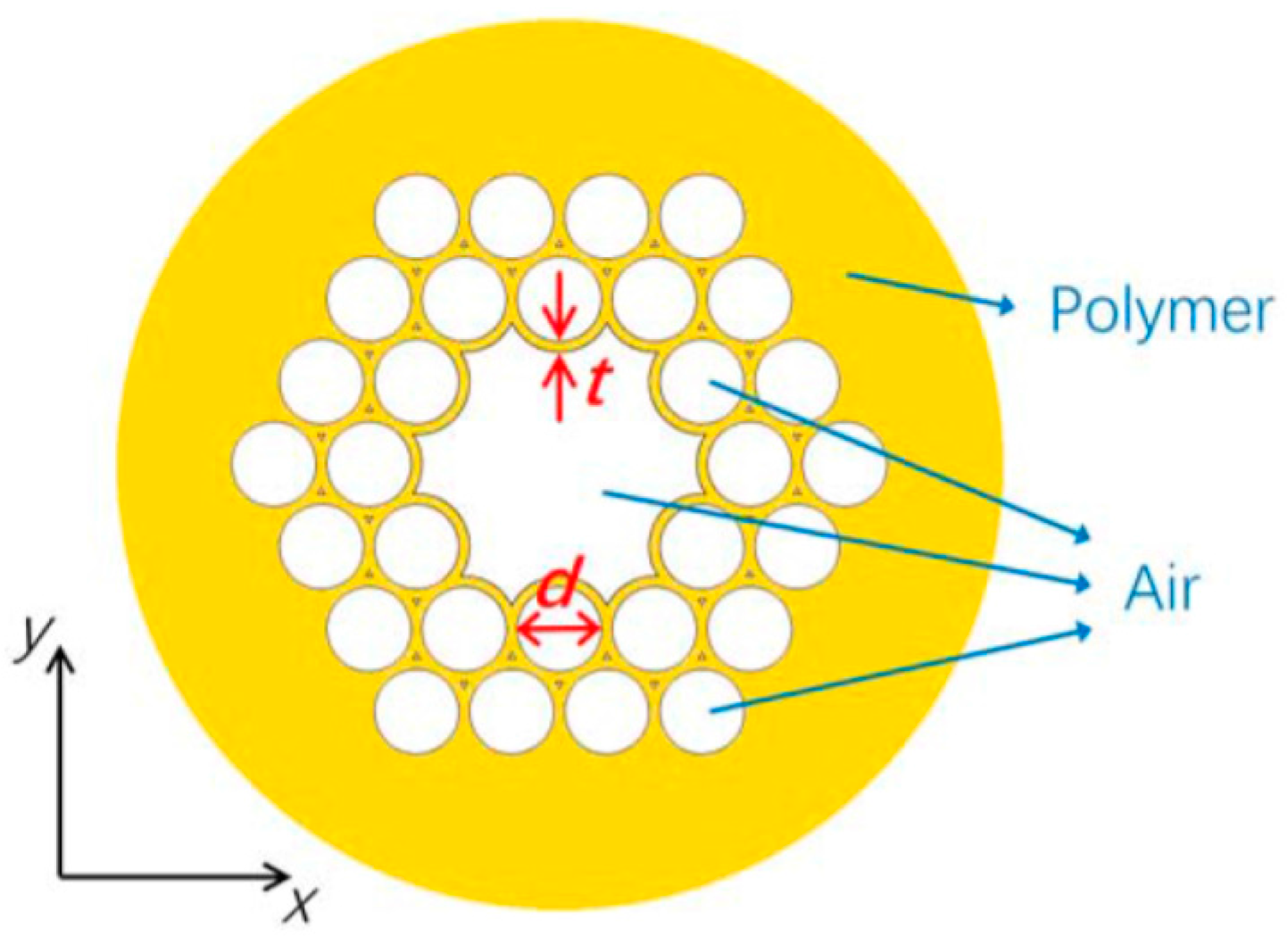
The hollow-core PCF with Kagome lattice was proposed to explore terahertz OAM modes transmission in an anti-resonant reflecting optical waveguide (ARROW), as shown in Figure 8 [44]. The values of structure parameters t and d are 0.3 mm and 2.4 mm, respectively. Three OAM modes (, and ) can be supported in the fiber. The fiber covers a broad bandwidth of 0.25 THz, and the purity values of OAM modes are larger than 0.9. Unlike the conventional fibers, the terahertz Kagome hollow-core PCFs suffer from the higher modal confinement losses with the order of 10–3 dB/cm. The performance of this fiber needed to be continuously improved by optimizing the fiber structure.
The performances of the OAM fibers based on PCF structures are summarized in Table 2, in which we can see a roughly development footprint.
4. Challenges and Prospects
More and more attention is focusing on the PCF structure for transmitting OAM modes, because PCF provides more degrees of freedom for optimizing the fiber performance. However, we also have a long way to go. Although we can design more and more PCF structures supporting more OAM modes, it is difficult to fabricate such PCFs because majority of those PCFs have complicated structure. So far, most of PCFs designed to transmit OAM modes can only be found in theoretical papers; almost no PCF was actually fabricated, except for the helically twisted PCF. The reason is that during the process of the fabrication of such PCF structure, the temperature and the drawing speed need to be precisely controlled to prevent the collapse of air holes. Therefore, design and fabrication of the novel PCF structures for better performance of OAM modes transmission are two roads we have to make an effort to go down.
Another road we must go down is the PCF-based OAM mode devices design. For example, the PCF-based OAM fiber amplifier with a single pump can amplify all channel signals in a PCF-based OAM fiber that should be designed and fabricated, because this kind of fiber amplifier will match PCF-based OAM transmission fiber and reduce the number of the amplifiers (single mode fiber based) in OAM mode division multiplexing (MDM) communication systems. In addition, band rejection filters, sensors, multiplexers and demultiplexers, switching devices, supercontinuum generator, and dispersion control utilizing PCF-based structure are promising effort directions.
The most possible scenario, in which the PCF-based OAM fibers can play a significant role, is the short haul communication systems connecting the data processing centers with dense transmission data, in which currently many single mode fibers are needed to link between the data processing centers. The PCF-based OAM fiber can cut the number of the fibers and connectors and reduce the complexity of the system and cost savings.
5. Conclusions
In this paper, we review the recent main achievements in designing OAM mode fibers based on PCF structures. Based on five requirements for the design rules of OAM fibers for the stable transmission of OAM modes, we summarize the reasons why the PCF-based fibers can support OAM modes and possess some advantages over current ring core OAM fibers. The OAM fiber based on the C-PCF structure reveals some good features, such as the good quality of OAM transmission modes, enough effective index separation, low confinement loss, flat dispersion, a large effective mode area, and a low nonlinear coefficient. At the same time, we also compare transmission properties between the OAM fiber based on the C-PCF structure and the ring core fiber, as well as the amplification properties among three OAM EDFAs. Also, it shows that the OAM fiber based on the PCF structure is one promising choice of the OAM fibers. Furthermore, the development footprints of research works in OAM fibers based on the PCF structure are also summarized. Finally, the challenges and prospects are discussed.
Acknowledgments
The authors would like to acknowledge financial support from the National Natural Science Foundation of China (NSFC) (61571057, 61527820, 61575082) and the Fund of State Key Laboratory of Information Photonics and Optical Communications (Beijing University of Posts and Telecommunications) (IPOC2016ZZ04).
Author Contributions
Hu Zhang and Xiaoguang Zhang conceived and designed the manuscript, Hu Zhang wrote the manuscript, and Xiaoguang Zhang modified the manuscript and confirmed the final version to be submitted; Hui Li and Yifan Deng collected and analyzed the data; Lixia Xi, Xianfeng Tang and Wenbo Zhang researched the literatures and calculated the data of figures and tables.
Conflicts of Interest
The authors declare no conflict of interest.
References
- Richardson, D.J.; Fini, J.M.; Nelson, L.E. Space-division multiplexing in optical fibres. Nat. Photon. 2013, 7, 354–362. [Google Scholar] [CrossRef]
- Zhu, B.; Taunay, T.F.; Fishteyn, M.; Liu, X.; Chandrasekhar, S.; Yan, M.F.; Fini, J.M.; Monberg, E.M.; Dimarcello, F.V. 112-Tb/s Space-division multiplexed DWDM transmission with 14-b/s/Hz aggregate spectral efficiency over a 76.8-km seven-core fiber. Opt. Exp. 2011, 19, 16665–16671. [Google Scholar] [CrossRef] [PubMed]
- Sakaguchi, J.; Puttnam, B.J.; Klaus, W.; Awaji, Y.; Wada, N.; Kanno, A.; Kawanishi, T.; Imamura, K.; Inaba, H.; Mukasa, K.; et al. 19-core fiber transmission of 19×100×172-Gb/s SDMWDM-PDM-QPSK signal at 305 Tb/s. In Proceedings of the Optical Fiber Communication Conference, Los Angeles, CA, USA, 4–8 March 2012; pp. 1–3, paper PDP5C.1. [Google Scholar]
- Allen, L.; Beijersbergen, M.W.; Spreeuw, R.; Woerdman, J. Orbital angular momentum of light and the transformation of Laguerre-Gaussian laser modes. Phys. Rev. A 1992, 45, 8185–8189. [Google Scholar] [CrossRef] [PubMed]
- Ramachandran, S.; Kristensen, P.; Yan, M.F. Generation and propagation of radially polarized beams in optical fibers. Opt. Lett. 2009, 34, 2525–2527. [Google Scholar] [CrossRef] [PubMed]
- Yao, A.M.; Padgett, M. J. Orbital angular momentum: Origins, behavior and applications. Adv. Opt. Photon. 2011, 3, 161–204. [Google Scholar] [CrossRef]
- Golowich, S. Asymptotic theory of strong spin-orbit coupling in optical fiber. Opt. Lett. 2014, 39, 92–95. [Google Scholar] [CrossRef] [PubMed]
- Randel, S.; Ryf, R.; Sierra, A.; Winzer, P.J.; Gnauck, A.H.; Bolle, C.A.; Essiambre, R.-J.; Peckham, D.W.; McCurdy, A.; Lingle, R. 6×56-Gb/s mode-division multiplexed transmission over 33-km few-mode fiber enabled by 6×6 MIMO equalization. Opt. Exp. 2011, 19, 16697–16707. [Google Scholar] [CrossRef] [PubMed]
- Ryf, R.; Randel, S.; Gnauck, A.H.; Bolle, C.; Sierra, A.; Mumtaz, S.; Esmaeelpour, M.; Burrows, E.C.; Essiambre, R.-J.; Winzer, P.J.; et al. Mode-division multiplexing over 96 km of few-mode fiber using coherent 6×6 Mimo processing. J. Lightwave Technol. 2012, 30, 521–531. [Google Scholar] [CrossRef]
- Li, S.; Wang, J. Multi-orbital-angular-momentum multi-ring fiber for high-density space-division multiplexing. IEEE Photon. J. 2013, 5, 7101007. [Google Scholar]
- Bozinovic, N.; Yue, Y.; Ren, Y.; Tur, M.; Kristensen, P.; Huang, H.; Willner, A.E.; Ramachandran, S. Terabit scale orbital angular momentum mode division multiplexing in fibers. Science 2013, 340, 1545–1548. [Google Scholar] [CrossRef] [PubMed]
- Willner, A.E.; Huang, H.; Yan, Y.; Ren, Y.; Ahmed, N.; Xie, G.; Bao, C.; Li, L.; Cao, Y.; Zhao, Z.; et al. Optical communications using orbital angular momentum beams. Adv. Opt. Photon. 2015, 7, 66–106. [Google Scholar] [CrossRef]
- Carpenter, J.A.; Thomsen, B.C.; Wilkinson, T.D. Optical vortex based mode division multiplexing over graded-index multimode fibre. In Proceedings of the Optical Fiber Communication Conference/National Fiber Optic Engineers Conference, Anaheim, CA, USA, 17–21 March 2013; pp. 1–3. [Google Scholar]
- Ramachandran, S.; Kristensen, P. Optical vortices in fiber. Nanophotonics 2013, 2, 455–474. [Google Scholar] [CrossRef]
- Yan, Y.; Yue, Y.; Huang, H.; Yang, J.; Chitgarha, M.R.; Ahmed, N.; Tur, M.; Dolinar, S.J.; Willner, A.E. Efficient generation and multiplexing of optical orbital angular momentum modes in a ring fiber by using multiple coherent inputs. Opt. Lett. 2012, 37, 3645–3647. [Google Scholar] [CrossRef] [PubMed]
- Yue, Y.; Yan, Y.; Ahmed, N.; Yang, J.; Zhang, L.; Ren, Y.; Huang, H.; Birnbaum, K.M.; Erkmen, B.I.; Dolinar, S.; et al. Mode properties and propagation effects of optical orbital angular momentum (OAM) modes in a ring fiber. IEEE Photon. J. 2012, 4, 535–543. [Google Scholar]
- Gregg, P.; Kristensen, P.; Golowich, S.; Olsen, J.; Steinvurzel, P.; Ramachandran, S. Stable transmission of 12 oam states in air-core fiber. In Proceedings of the Conference on Lasers and Electro-Optics, San Jose, CA, USA, 9–14 June 2013; pp. 1–3. [Google Scholar]
- Brunet, C.; Ung, B.; Messaddeq, Y.; LaRochelle, S.; Bernier, E.; Rusch, L.A. Design of an optical fiber supporting 16 OAM modes. In Proceedings of the Optical Fiber Communication Conference, San Francisco, CA, USA, 9–13 March 2014; pp. 1–3. [Google Scholar]
- Brunet, C.; Ung, B.; Bélanger, P.A.; Messaddeq, Y.; LaRochelleand, S.; Rusch, L.A. Vector mode analysis of ring-core fibers: Design tools for spatial division multiplexing. J. Lightwave Technol. 2014, 32, 4046–4057. [Google Scholar] [CrossRef]
- Brunet, C.; Vaity, P.; Messaddeq, Y.; LaRochelle, S.; Rusch, L.A. Design, fabrication and validation of an OAM fiber supporting 36 states. Opt. Express 2014, 22, 26117–26127. [Google Scholar] [CrossRef] [PubMed]
- Brunet, C.; Ung, B.; Vaity, P.; Wang, L.; Messaddeq, Y.; LaRochelle, S.; Rusch, L.A. Design of a family of ring-core fibers for OAM transmission studies. Opt. Express 2015, 23, 10553–10563. [Google Scholar] [CrossRef] [PubMed]
- Ramachandran, S.; Gregg, P.; Kristensen, P.; Golowich, S.E. On the scalability of ring fiber designs for OAM multiplexing. Opt. Express 2015, 23, 3721–3730. [Google Scholar] [CrossRef] [PubMed]
- Gregg, P.; Kristensen, P.; Ramachandran, S. Conservation of orbital angular momentum in air core optical fibers. Optica 2015, 2, 2334–2536. [Google Scholar] [CrossRef]
- Brunet, C.; Rusch, L.A. Optical fibers for the transmission of orbital angular momentum modes. Opt. Fiber Technol. 2016, 31, 172–177. [Google Scholar] [CrossRef]
- Russell, P.S.J. Photonic crystal fibers. J. Lightwave Technol. 2006, 24, 4729–4749. [Google Scholar] [CrossRef]
- Benabid, F.; Russell, P.S.J. Hollow core photonic crystal fibers: progress and prospects. Proc. SPIE 2005, 5733, 176–189. [Google Scholar]
- Mortensen, N.A.; Nielsen, M.D.; Folkenberg, J.R.; Petersson, A.; Simonsen, H.R. Improved large-mode-area endlessly single-mode photonic crystal fibers. Opt. Lett. 2003, 28, 393–395. [Google Scholar] [CrossRef] [PubMed]
- Amezcua-Correa, R.; Broderick, N.G.; Petrovich, M.N.; Poletti, F.; Richardson, D.J. Design of 7 and 19 cells core air-guiding photonic crystal fibers for low-loss, wide bandwidth and dispersion controlled operation. Opt. Express 2007, 15, 17577–17586. [Google Scholar] [CrossRef] [PubMed]
- Lægsgaard, J.; Roberts, P.J.; Bache, M. Tailoring the dispersion properties of photonic crystal fibers. Opt. Quant. Electron. 2007, 39, 995–1008. [Google Scholar] [CrossRef]
- Yue, Y.; Zhang, L.; Yan, Y.; Ahmed, N.; Yang, J.; Huang, H.; Ren, Y.; Dolinar, S.; Tur, M.; Willner, A.E. Octave-spanning supercontinuum generation of vortices in an As2S3 ring photonic crystal fiber. Opt. Lett. 2012, 37, 1889–1891. [Google Scholar] [CrossRef] [PubMed]
- Wong, G.K.; Kang, M.S.; Lee, H.W.; Biancalana, F.; Conti, C.; Weiss, T.; Russell, P.S. Excitation of orbital angular momentum resonances in helically twisted photonic crystal fiber. Science 2012, 337, 446–449. [Google Scholar] [CrossRef] [PubMed]
- Xi, X.M.; Wong, G.K.L.; Frosz, M.H.; Babic, F.; Ahmed, G.; Jiang, X.; Euser, T.G.; Russell, P.S.J. Orbital angular-momentum-preserving helical Bloch modes in twisted photonic crystal fiber. Optica 2014, 1, 165–169. [Google Scholar] [CrossRef]
- Xi, X.M.; Weiss, T.; Wong, G.K.L.; Biancalana, F.; Barnett, S.M.; Padgett, M.J.; Russell, P.S.J. Optical activity in twisted solid-core photonic crystal fibers. Phys. Rev. Lett. 2013, 110, 143903. [Google Scholar] [CrossRef] [PubMed]
- Russell, P.S.J.; Bevarat, R.; Wong, G.K.L. Helically twisted photonic crystal fibres. Phil. Trans. R. Soc. A 2017, 375, 20150440. [Google Scholar] [CrossRef] [PubMed]
- Ye, J.; Li, Y.; Han, Y.; Deng, D.; Guo, Z.; Gao, J.; Sun, Q.; Liu, Y.; Qu, S. Excitation and separation of vortex modes in twisted air-core fiber. Opt. Express 2016, 24, 8310–8316. [Google Scholar] [CrossRef] [PubMed]
- Zhang, H.; Zhang, W.; Xi, L.; Tang, X.; Tian, W.; Zhang, X.; Zhang, X. Design of a Circular Photonic Crystal Fiber Supporting OAM Modes. In Proceedings of the Asia Communications and Photonics Conference, Hong Kong, China, 19–23 November 2015; pp. 1–3. [Google Scholar]
- Chen, C.; Zhou, G.; Zhou, G.; Xu, M.; Hou, Z.; Xia, C.; Yuan, J. A multi-orbital-angular-momentum multi-ring micro-structured fiber with ultra-high-density and low-level crosstalk. Opt. Commun. 2016, 368, 27–33. [Google Scholar] [CrossRef]
- Zhou, G.; Chen, C.; Xu, M.; Xia, C.; Hou, Z. Design and Analysis of a Microstructure Ring Fiber for Orbital Angular Momentum Transmission. IEEE Photon. J. 2016, 8, 7802512. [Google Scholar] [CrossRef]
- Zhang, H.; Zhang, W.; Xi, L.; Tang, X.; Zhang, X.; Zhang, X. A New Type Circular Photonic Crystal Fiber for Orbital Angular Momentum Mode Transmission. IEEE Photon. Technol. Lett. 2016, 28, 1426–1429. [Google Scholar] [CrossRef]
- Hu, Z.; Huang, Y.; Luo, A.; Cui, H.; Luo, Z.; Xu, W. Photonic crystal fiber for supporting 26 orbital angular momentum modes. Opt. Express 2016, 24, 17285–17291. [Google Scholar] [CrossRef] [PubMed]
- Li, H.; Ren, G.; Lian, Y.; Zhu, B.; Tang, M.; Zhao, Y.; Jian, S. Broadband orbital angular momentum transmission using a hollow-core photonic bandgap fiber. Opt. Lett. 2016, 41, 3591–3594. [Google Scholar] [CrossRef] [PubMed]
- Tian, W.; Zhang, H.; Zhang, X.; Xi, L.; Zhang, W.; Tang, X. A circular photonic crystal fiber supporting 26 OAM modes. Opt. Fiber Technol. 2016, 30, 184–189. [Google Scholar] [CrossRef]
- Zhang, H.; Zhang, W.; Xi, L.; Tang, X.; Zhang, X. A New Design of a Circular Photonic Crystal Fiber Supporting 42 OAM Modes. In Proceedings of the Australian Conference on Optical Fibre Technology, Sydney, Australia, 5–8 September 2016; pp. 1–2. [Google Scholar]
- Li, H.; Ren, G.; Zhu, B.; Gao, Y.; Yin, B.; Wang, J.; Jian, S. Guiding terahertz orbital angular momentum beams in multimode Kagome hollow-core fibers. Opt. Lett. 2017, 42, 179–183. [Google Scholar] [CrossRef] [PubMed]
- Zhang, H.; Zhang, X.; Li, H.; Deng, Y.; Zhang, X.; Xi, L.; Tang, X.; Zhang, W. A design strategy of the circular photonic crystal fiber supporting good quality orbital angular momentum mode transmission. Opt. Commun. 2017, 397, 59–66. [Google Scholar] [CrossRef]
- Deng, Y.; Zhang, H.; Li, H.; Tang, X.; Zhang, X.; Xi, L.; Zhang, W.; Zhang, X. Erbium-doped amplification in circular photonic crystal fiber supporting orbital angular momentum modes. Appl. Opt. 2017, 56, 1748–1752. [Google Scholar] [CrossRef] [PubMed]
- Ma, J.; Xia, F.; Li, S.; Wang, J. Design of Orbital Angular Momentum (OAM) Erbium Doped Fiber Amplifier with Low Differential Modal Gain. In Proceedings of the Optical Fiber Communication Conference/National Fiber Optic Engineers Conference, Los Angeles, CA, USA, 24–26 March 2015; pp. 1–3. [Google Scholar]
- Kang, Q.; Gregg, P.; Jung, Y.; Lim, E.L.; Alam, S.; Ramachandran, S.; Richardson, D.J. Amplification of 12 OAM Modes in an air-core erbium doped fiber. Opt. Express 2015, 23, 28341–28348. [Google Scholar] [CrossRef] [PubMed]
Figure 1.
Cross section and structure parameters of (a) ring photonic crystal fiber (PCF) (reprinted with permission from [30]. Copyright 2012 Optical Society of America), (b) the twisted air-core PCF (Reprinted from [31] by permission from AAAS), and (c) hollow-core photonic bandgap fiber (HC-PBGF) (reprinted with permission from [41]. Copyright 2016 Optical Society of America).
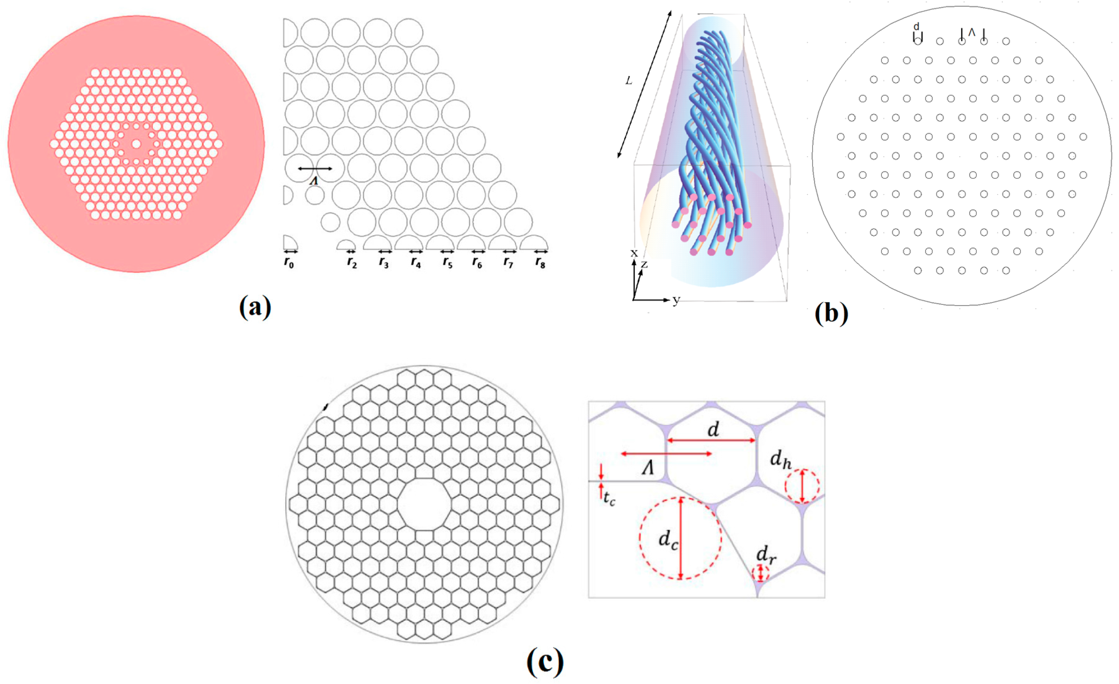
Figure 2.
Cross-section and main parameters of C-PCF. Reprinted with permission from [36]. Copyright 2015 Optical Society of America.
Figure 2.
Cross-section and main parameters of C-PCF. Reprinted with permission from [36]. Copyright 2015 Optical Society of America.
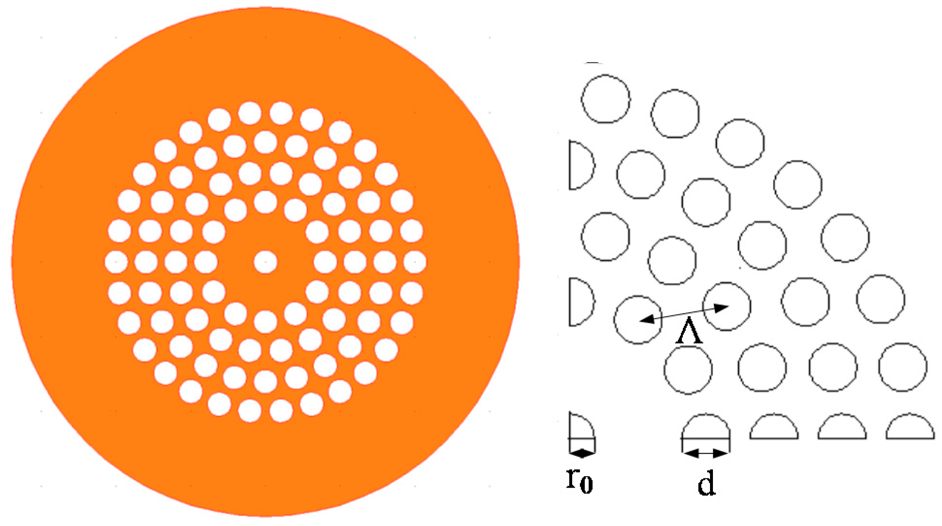
Figure 3.
Cross section and structure parameters of (a) the microstructure ring fiber (reprinted from [37] by permission from Elsevier), and (b) ring PCF (reprinted with permission from [40]. Copyright 2016 Optical Society of America).

Figure 4.
Cross-section and main parameters of the designed circular photonic crystal fibers (C-PCFs) for (a) the fiber base; (b) C-PCF 1#; (c) C-PCF 2#; and (d) C-PCF 3#. Reprinted from [45] by permission from Elsevier.
Figure 4.
Cross-section and main parameters of the designed circular photonic crystal fibers (C-PCFs) for (a) the fiber base; (b) C-PCF 1#; (c) C-PCF 2#; and (d) C-PCF 3#. Reprinted from [45] by permission from Elsevier.
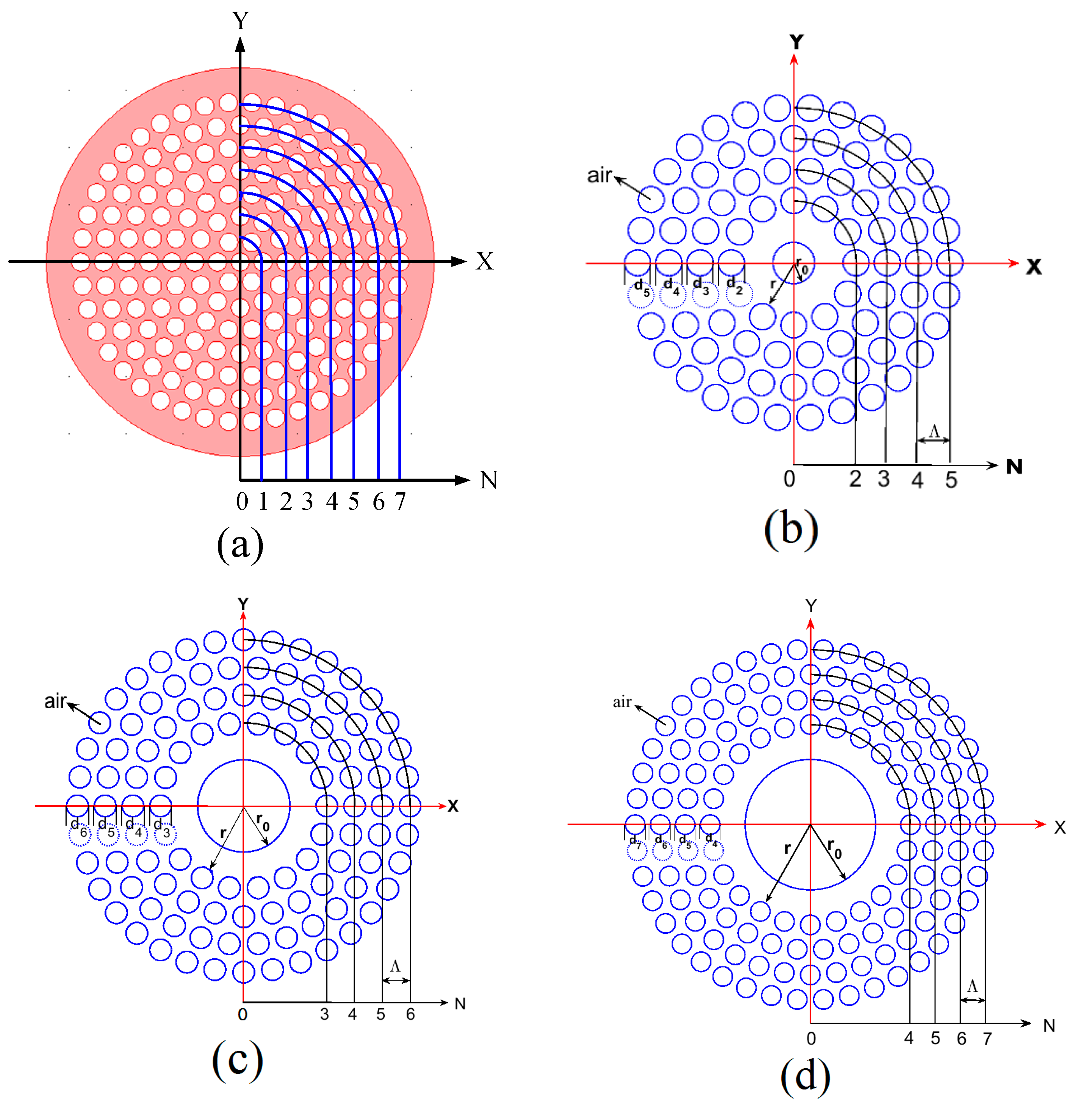
Figure 5.
(a) Modal map of the ring core fiber; (b) modal map of the C-PCF corresponding to removing off the first one air-hole ring (the C-PCF 1#).
Figure 5.
(a) Modal map of the ring core fiber; (b) modal map of the C-PCF corresponding to removing off the first one air-hole ring (the C-PCF 1#).
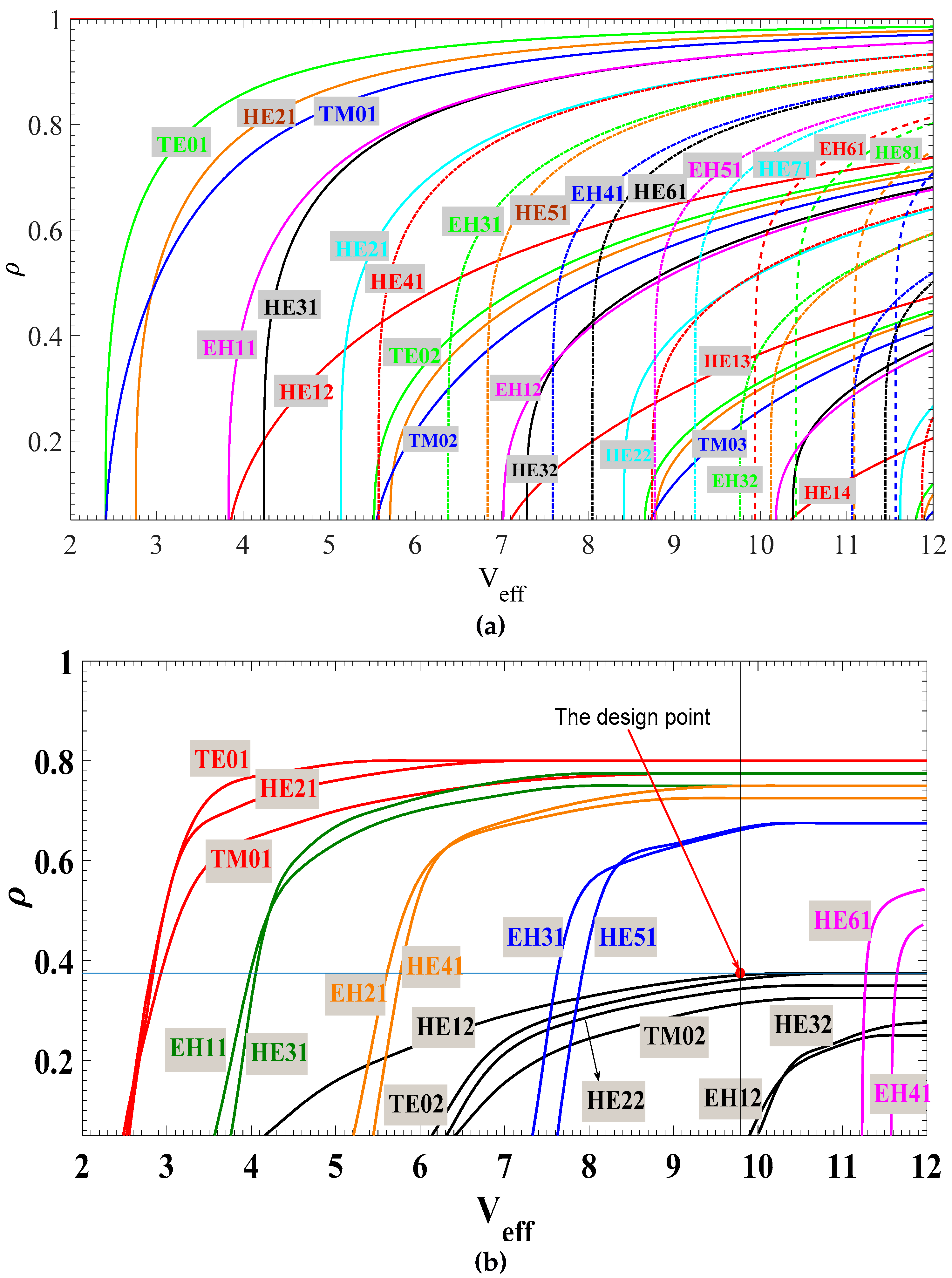
Figure 6.
Dispersion as a function of wavelength for different vector modes of (a) the C-PCF 3# (reprinted from [45] by permission from Elsevier); (b) the air-core ring fiber (reprinted with permission from [20]. Copyright 2014 Optical Society of America).
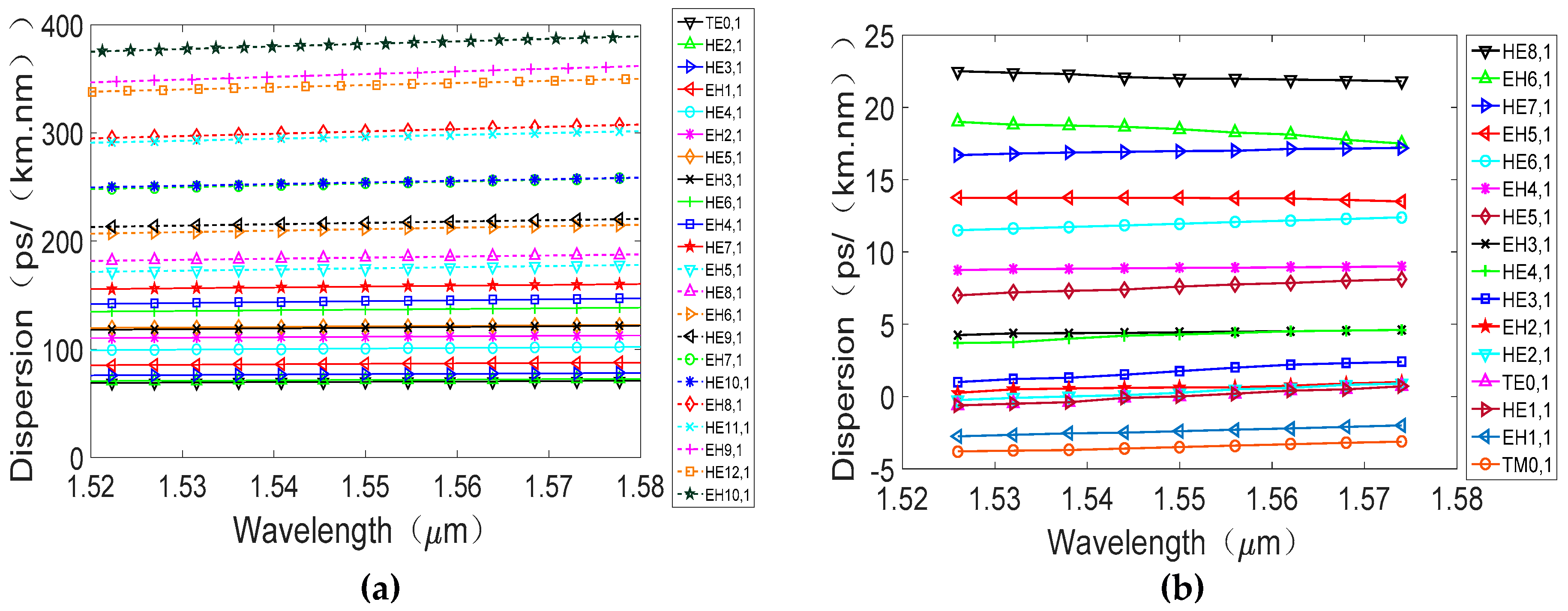
Figure 7.
(a) The gain; (b) noise figure (NF); and (c) the differential mode gain (DMG) as a function of wavelength for different OAM EDFA (Data from Ref. [46,47,48]).

Figure 8.
Cross section of the Kagome lattice hollow-core PCF. Reprinted with permission from [44]. Copyright 2017 Optical Society of America.
Figure 8.
Cross section of the Kagome lattice hollow-core PCF. Reprinted with permission from [44]. Copyright 2017 Optical Society of America.


Table 1.
Structure parameters of C-PCF family and orbital angular momentum (OAM) modes supported.
| C-PCF 1# | C-PCF 2# | C-PCF 3# | |
|---|---|---|---|
| Refractive index | Silica: n = 1.444, air holes: n = 1.000; ncl = 1.231, (nco/ncl)2 = 1.376 | ||
| Common parameters | Air hole pitch: Λ = 2.0 μm, diameters of the air holes: dn = 1.6 μm, dn/Λ = 0.8 | ||
| Outer radius | r = 3.2 μm | r = 5.2 μm | r = 7.2 μm |
| Effective normalized frequency | Veff = 9.79 | Veff = 15.91 | Veff = 22.04 |
| OAM modes | l = 1~4, 14 states | l = 1~7, 26 states | l = 1~11, 42 states |
| Bandwidth | 560 nm (1.25–1.81 μm) | 480 nm (1.25–1.73 μm) | 460 nm (1.25–1.71 μm) |
Table 2.
OAM fibers based on PCF structures.
| Year | Author | Lattice | Material | Number of OAM Modes | Supported OAM Modes | Bandwidth | Reference |
|---|---|---|---|---|---|---|---|
| 2012 | Y. Yue et al. | Hexagon | As2S3 | 2 | OAM1,1 | 522 nm | [30] |
| 2012 | G.K.L.Wong et al. | Hexagon | SiO2 | 1 | OAM+1,1 ( OAM−1,1) | [31] | |
| 2015 1 | H. Zhang et al. | Circular | SiO2 | 10 | OAM1,1 OAM2,1 OAM3,1 | [36] | |
| 2016 | C. Chen et al. | Circular | SiO2 | 34 | OAM1,1, …, OAM9,1 | 60 nm | [37] |
| 2016 | G. Zhou et al. | Circular | SiO2 | 34 | OAM1,1, …, OAM9,1 | [38] | |
| 2016 2 | H. Zhang et al. | Circular | SiO2 | 14 | OAM1,1, …, OAM4,1 | 560 nm | [39] |
| 2016 | W. Tian et al. | Circular | SiO2 | 26 | OAM1,1, …, OAM7,1 | 750 nm | [42] |
| 2016 | Z. Hu et al. | Circular | As2S3 | 26 | OAM1,1, …, OAM7,1 | [40] | |
| 2017 | H. Li et al. | Hexagon(PBG) | SiO2 | 2 | OAM1,1 | 240 nm | [41] |
| 2017 | H. Li et al. | Kagome | Polymer | 3 | , , | 0.25 THz | [44] |
| 2017 | H. Zhang et al. | Circular | SiO2 | 42 | OAM1,1, …, OAM11,1 | 460 nm | [45] |
1 manuscript received in July 31, 2015; 2 manuscript received in October 26, 2015.
© 2017 by the authors. Licensee MDPI, Basel, Switzerland. This article is an open access article distributed under the terms and conditions of the Creative Commons Attribution (CC BY) license (http://creativecommons.org/licenses/by/4.0/).
Share and Cite
MDPI and ACS Style
Zhang, H.; Zhang, X.; Li, H.; Deng, Y.; Xi, L.; Tang, X.; Zhang, W. The Orbital Angular Momentum Modes Supporting Fibers Based on the Photonic Crystal Fiber Structure. Crystals 2017, 7, 286. https://doi.org/10.3390/cryst7100286
AMA Style
Zhang H, Zhang X, Li H, Deng Y, Xi L, Tang X, Zhang W. The Orbital Angular Momentum Modes Supporting Fibers Based on the Photonic Crystal Fiber Structure. Crystals. 2017; 7(10):286. https://doi.org/10.3390/cryst7100286
Chicago/Turabian StyleZhang, Hu, Xiaoguang Zhang, Hui Li, Yifan Deng, Lixia Xi, Xianfeng Tang, and Wenbo Zhang. 2017. "The Orbital Angular Momentum Modes Supporting Fibers Based on the Photonic Crystal Fiber Structure" Crystals 7, no. 10: 286. https://doi.org/10.3390/cryst7100286
Note that from the first issue of 2016, this journal uses article numbers instead of page numbers. See further details here.