
Atomistic Studies of Nanoindentation—A Review of Recent Advances


1
Facultad de Ciencias Exactas y Naturales, Universidad Nacional de Cuyo and CONICET, Mendoza 5500, Argentina
2
Physics Department and Research Center OPTIMAS, University Kaiserslautern, Erwin-Schrödinger-Straße, D-67663 Kaiserslautern, Germany
*
Author to whom correspondence should be addressed.
Crystals 2017, 7(10), 293; https://doi.org/10.3390/cryst7100293
Submission received: 12 September 2017
/
Revised: 25 September 2017
/
Accepted: 26 September 2017
/
Published: 29 September 2017
(This article belongs to the Special Issue Crystal Indentation Hardness)
Abstract
:This review covers areas where our understanding of the mechanisms underlying nanoindentation has been increased by atomistic studies of the nanoindentation process. While such studies have been performed now for more than 20 years, recent investigations have demonstrated that the peculiar features of nanoplasticity generated during indentation can be analyzed in considerable detail by this technique. Topics covered include: nucleation of dislocations in ideal crystals, effect of surface orientation, effect of crystallography (fcc, bcc, hcp), effect of surface and bulk damage on plasticity, nanocrystalline samples, and multiple (sequential) indentation. In addition we discuss related features, such as the influence of tip geometry on the indentation and the role of adhesive forces, and how pre-existing plasticity affects nanoindentation.
1. Introduction
Nanoindentation is a technique commonly used to provide information about the elastic modulus and hardness of materials [1,2]. This technique has provided insights into a broad range of material properties; as examples we mention the indentation cracking of brittle thin films on brittle substrates [3]; the fracture toughness, adhesion and mechanical properties of dielectric thin films [4]; the strain hardening and recovery in a bulk metallic glass [5]; the phase transformation of titanium dioxide thin films produced by filtered arc deposition [6]; superhard materials [7]; and even the investigation of biomaterials, such as the mechanical properties of human enamel [8]. Nanoindentation testing has become of wide-spread use when modern modern experimental testing methods were combined with the Oliver-Pharr [9] analysis. Further applications of this method are found in the investigation of the deformation mechanics of nanoparticles, micro- and nanopillars, microbeams, micro- and nanofibers, membranes, and nanofilms; this wide variety of structures are ubiquitous to the field of nanotechnology [10].
Nanoindentation is intimately related to the problem of contact between two bodies, where an indenter exerts force on a material. Contact mechanics involves all the spatial scales, from atomistic to continuum, and many temporal scales, ranging from the period of atomic vibrations to the duration of contact. It also comprises complex mechanisms such as many-body interactions, plasticity, heating and even phase transformations. Luan and Robbins [11] showed that a nanoscale contact is governed by atomistic phenomena and that it is frequent to find plastic deformation in the form of dislocation nucleation on the surface or the flattening of asperities [12]. The scale of these phenomena render their in situ experimental observation extremely difficult and that is the reason why computational tools help on the elucidation of the deformation mechanisms taking place.
The understanding of the deformation mechanisms during nanoindentation at the atomic scale has gained considerably from atomistic simulations [13]. Among the landmark contributions we mention the paper by Landman et al. [14] which helped to understand the jump-to-contact phenomenon during indentation. The contribution by Hoover et al. [15] showed that the predicted hardness was strongly influenced by the interatomic potential, temperature, and indenter speed used in the simulations. Harrison et al. [16] published simulation results of nanoindentation on the diamond (111) surface and found a fracture mode of stress relaxation under the indenter. Sinnott et al. [17] performed atomistic simulations of the nanometer-scale indentation of amorphous-carbon thin films providing qualitative insight into the mechanical deformation processes that take place during indentation, and quantitative predictions that compare well with experimental data.
Later Kelchner et al. [18] performed molecular dynamics (MD) simulations of spherical indentation in Au, and since then MD simulations have been extensively applied to study plasticity mechanisms during indentation processes. This paper reviews some of the most relevant contributions to nanoindentation that were made possible by atomistic simulations.
In a previous review [19] we gave an introduction to the methods used in atomistic simulation of nanoindentation, and in the analysis and interpretation of such simulations. A remarkable outcome of such simulations is the possibility to identify all features (peaks, load drops, etc.) of the load-depth curve with the underlying plastic changes in the material, i.e., with the generation of dislocations, their reaction, or the emission of dislocation loops. Thus in particular the nucleation of dislocations underneath the indent tip, the dissociation of prismatic loops from the network adherent to the indent pit, and the generation of pile-up surrounding the pit has been studied in detail. In the present review we do not want to repeat this analysis, but rather focus on recent advances obtained after the writing of our last review [19]. It thus exemplifies that the field of atomistic modeling of nanoindentation is both active and continues obtaining relevant results and insights.
The topics covered in this review include ideal crystals, effect of surface orientation and crystallography (Section 2), the effect of surface and bulk defects on plasticity (Section 3), multiple indentation (Section 4), the effect of the tip modeling (Section 5) and the role of adhesive forces and tip wetting (Section 6). Finally we conclude on current challenges in the field (Section 7).
2. Ideal Crystals, Effect of Surface Orientation and Crystallography
2.1. Fcc Metals
Due to the abundance of fcc metals and the technological applications of some of them, metals with this structure were the first to be studied. The homogeneous nucleation and structure of dislocations in fcc metals under indentation was first studied by Kelchner et al. [18] and later by Van Vliet et al. [20] and Lee et al. [21]. The heterogeneous nucleation of dislocations at surface steps was first studied by Zimmerman et al. [22].
Dislocation slip in fcc crystals occurs along the close-packed plane, that is a plane of type . The primary glide system in this material class is the system. Immediately after nucleation, shear loops are formed that tend to attach to the indenter surface. Depending on the generalized stacking fault energies (SFEs), dislocations in fcc metals dissociate and form partials that are accompanied by stacking fault planes. The reaction of dislocations can generate prismatic loops that transport material away from the surface into the substrate. Depending on the surface orientation, if glide vectors are available that lie parallel to the surface—such as for a (111) surface—V-shaped loops are formed at the surface that are free to glide out of the high-stress indentation zone [23,24,25,26].
Li et al. [27] studied nanoindentation of Au and found good agreement of the yield strength of the single-indexed surfaces with experiment. In addition, they alloyed 5% of Zr, Cu and Ti to their Au crystal. They demonstrated that the difference of unstable and stable SFE—rather than the stable SFE itself—is a good indicator of the strength of alloys. This difference corresponds to the nucleation barrier for defects, and exhibits a strong correlation with the hardness of the alloys.
2.2. Bcc Metals
Prismatic loops are also formed in bcc metals, as was observed by Hagelaar et al. [30] during nanoindentation in tungsten. Upon indentation on a (111) surface loop generation was associated with shear stresses in their atomistic indenter. Considering tantalum as a model bcc material, Alcalá and co-workers [31] have shown that nanocontact plasticity occurs by the nucleation and propagation of twin and stacking fault bands driven by a combination of shear stresses and pressure. They suggested that dislocations appear after a thermally assisted twin annihilation and mentioned that this mechanism is common to other bcc metals.
Remington et al. [32] presented a comprehensive nanoindentation MD study of Ta single crystals along the three principal crystallographic orientations. They reported that after the formation and annihilation of planar defects similar to the ones reported by Alcalá et al. [31], shear loops form and propagate along directions. Consistent with bcc slip systems, the shear loops grow by the advance of their edge components while the screw components undergo limited cross-slip. Eventually the screw segments may annihilate each other since they have dislocation lines with opposite signs, and a prismatic loop is pinched off [32,33].
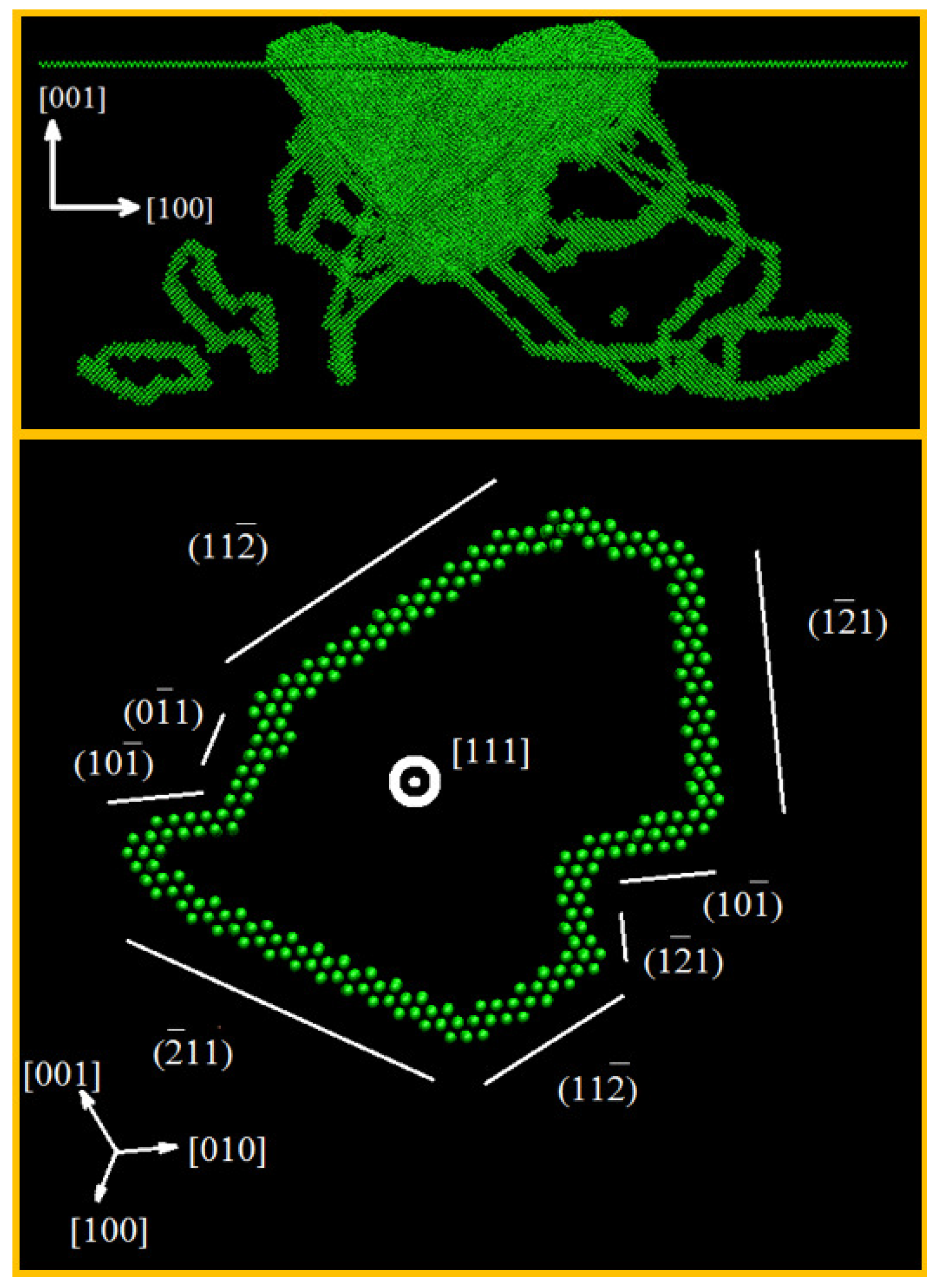
Figure 1 presents a side view of the indentation of a (001) Ta single crystal by an 8 nm diameter spherical indenter to a penetration of 5 nm, and a detailed view of a prismatic loop produced in the process. The loop is formed of several dislocation segments in several slip planes pertaining to slip systems with the same slip direction. For methodological details, the reader is referred to reference [33].
Twinning may play a role in the plasticity of several bcc metals. Goel et al. [34] investigated the role of twinning during the nanoindentation of Ta, finding evidence for a significant twinning anisotropy.
2.3. Hcp Metals
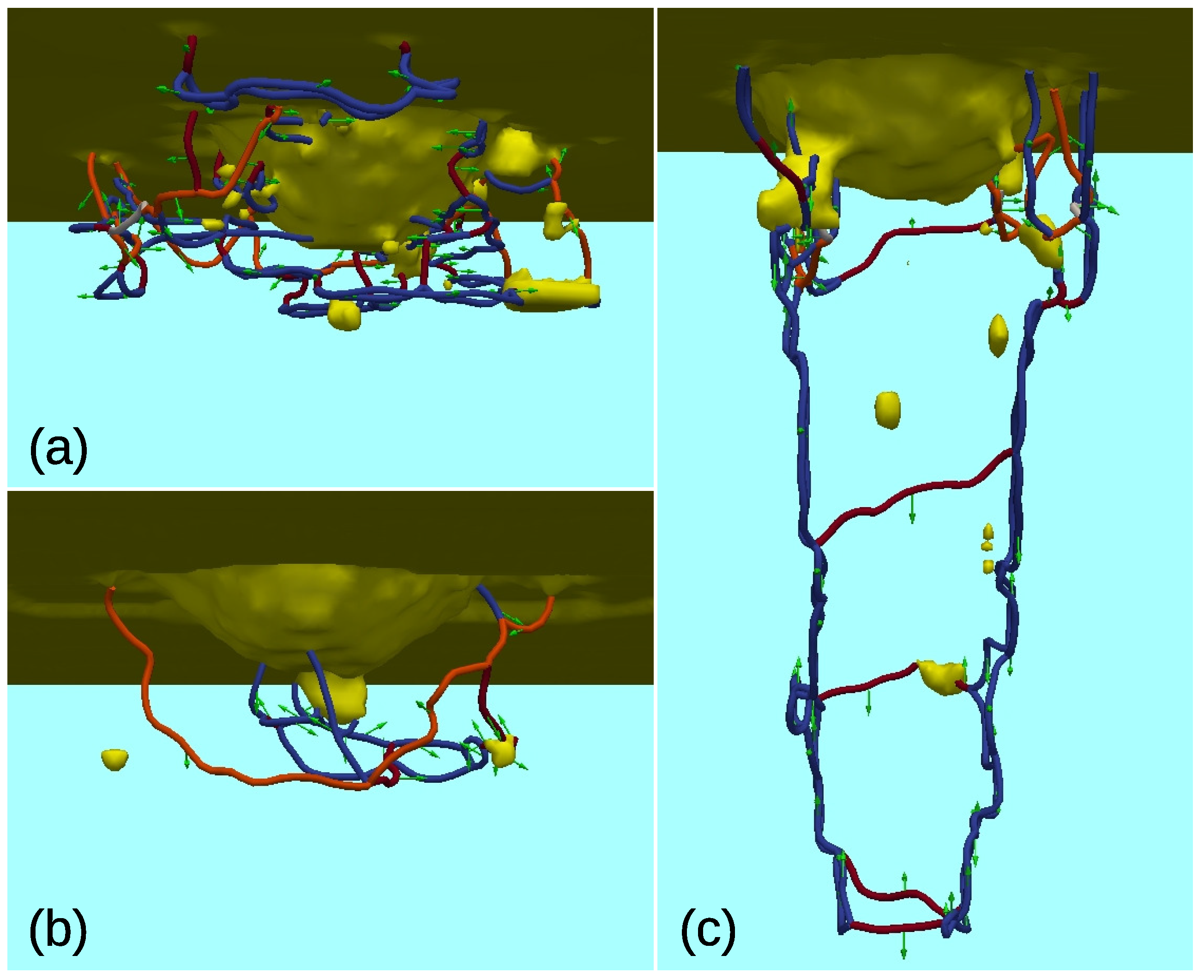
While nanoindentation in fcc and bcc metals has been characterized fairly well using MD simulation, little work has been published on the indentation of hcp metals, and only recently. Most of these studies are concerned with Mg [35,36,37], while Lu et al. [38] indent into Zr. In a comparative study, Alhafez et al. [39] simulated Mg, Ti, Zr in three different orientations; they found that here the surface crystallography plays a comparatively larger role than in the fcc and bcc materials. The reason is that the anisotropy of the crystal (unequal a and c axes) makes slip in the pertinent directions differ more pronouncedly than in the cubic crystal classes. In other words, slip by basal and prismatic or pyramidal dislocations shows more variety than in the fcc and bcc crystals. Figure 2 exemplifies the dislocation network generated by indentation in an hcp metal, Ti. Dislocations are dominated by the partials , while the perfect dislocations occur more rarely. Prismatic dislocation loops are emitted abundantly, leading to quite extended plastic zones. Figure 2 thus demonstrates the influence of surface orientation on the density of the network and the direction and intensity of loop emission.
2.4. Si
Non-metals have been investigated with less systematics than metals. An exception is provided by the important material Si. Already in our previous report [19] we mentioned a number of studies on Si [40,41,42]. Research in this material is still very active as is evidenced by the large number of recent publications [43,44,45,46,47,48].
All studies indicate that phase transformation—in particular to the amorphous state—contributes strongly to plasticity. An important issue concerns the the question in how far dislocations take part in the plasticity. Here a comparative study of indentation into Si [46] showed that the Stillinger-Weber potential [49] produces considerably more dislocations than the Tersoff potential [50], confirming earlier studies. The exact nature of the phases created is under discussion; but it seems that—at least for the Stillinger-Weber potential—the beta-tin phase is not formed, but the bct5 phase [45]. These results were recently corroborated and extended [47]. Already previously Mylvaganam and Zhang [44] studied the effect of crystal orientation on the formation of bct-5 silicon, using the Tersoff potential.
The nature of the plastic yield in Si is still under discussion [51]. While simulations using the Stillinger-Weber potential [49] determine dislocation nucleation and amorphization are the key contributors to plasticity [52], simulations with the Tersoff potential [50] find the solid-solid transformation to the beta-tin phase as initiator of the plastic yield [41].
Abrams et al. [48] use the Tersoff potential [50] to understand the influence of crystalline and amorphous phase transitions in Si on the extrusion behavior on the surface. They find that formation of the crystalline Si-III phase can be identified by a pop-in in the force-depth curve which is absent under amorphization; both phase transformations lead to material extrusion to the surface.
Du et al. [43] report a temperature effect in nanoindentation between 10 and 300 K; with plastic indentation depth increasing and hardness decreasing when temperature increases. In addition they find an influence of the temperature on the crystalline solid-solid transformations occurring under the Tersoff potential.
A recent review of machining of Si was provided by Goel et al. [53], including information on indentation [42]; these are based on simulations using the so-called analytical bond order potential by Erhart and Albe [54]. They emphasize the high pressures obtained in the indentation zone, which may reach up to 10 GPa in their example and are responsible for the phase transformations. In comparison, the temperatures reached in the zone are appreciable only when the indentation velocity exceeds several ten m/s; this will not be relevant for indentation experiments.
It must be concluded that the mechanism of plastic yield in Si is dominated or at least strongly influenced by phase transformations.
2.5. Other Materials
Richter et al. [55] applied the molecular dynamics technique to study the nanoindentation of graphite and diamond to support their experimental studies, giving an atomistic description of the indentation process.
Szlufarska et al. [56] performed molecular dynamics simulation of indentation of nano-crystalline silicon carbide predicting a crossover from intergranular continuous deformation to intragrain discrete deformation at a critical indentation depth. Walsh et al. [57] relied on MD simulations to probe silicon nitride films reporting amorphization and cracking with a marked anisotropy.
Energetic materials can also be studied by molecular dynamics simulations, as shown by Chen et al. [58] who used MD simulations with reactive force fields to study nanoindentation of cyclotrimethylenetrintramine (RDX) by a diamond indenter. They report on significant heating of the substrate in the vicinity of the indenter, resulting in the release of molecular fragments and migration of these molecules on the indenter surfaces.
Recently also the indentation of Cu-Zr metallic glasses was attempted [59,60,61]. The hardness was found to increase with Cu content. Pop-in events in the load-depth curve and plastic yield were related to shear band formation.
Comparatively little work was devoted to indentation into composites. Feng et al. [62] investigated indentation into a nanocomposite formed of WC and Co layers. Special attention was paid on the action of the semi-coherent interface; it was found that it triggers dislocation generation in Co, enhancing the ductility. Indentation directly on a heterointerface, formed of Al and Si crystallites, was performed in [63]. Here enhanced dislocation mobility of the Si dislocations, mediated by the nearby interface, was reported.
Recently, also high-entropy alloys were studied [64]. For an FeCrCuAlN alloy a high hardness of 15.4 GPa is found which is claimed to be due to the low SFE and the dense atomic arrangement in the slip plane of this alloy. Further atomistic indentation studies were devoted to c-BN [65], Ti-Al alloy [66], and (001) oriented strontium titanate [67].
3. Effect of Surface and Bulk Defects on Plasticity
The response of grain boundaries (GBs) and their role in the mechanical response under indentation has attracted much attention [68,69]. Feichtinger et al. [70] performed atomistic simulations of nanoindentation on nanocrystalline (nc) Au with grain diameters of 5 and 12 nm and found GBs acting as dislocation sinks and also observed GB sliding. Ma and Yang [71] observed heterogeneous nucleation of dislocations at GBs in nc Cu. Hasnaoui et al. [72] found that for cases where the indenter size is smaller than the grain size in nc Au, GBs not only act as dislocations sinks, but that they can also reflect or emit dislocations, depending on their local structure and stress distribution. Jang and Farkas [73] studied the interaction of lattice dislocations with a grain boundary during nanoindentation of Ni and found dislocation transmission across GBs.
Liu et al. [74] explored the grain size effect in nc Ni with grain sizes ranging from 5 nm to 40 nm and found inverse Hall-Petch effect for the whole range, grain boundary absorption and that the area of the plastic zone generated is strongly dependent on the GB density. However, Huang et al. [75] only found inverse Hall-Petch effect for grain sizes below 7 nm in nc Cu. In addition they reported stress-induced grain growth as well as grain rotation as the cause for grain coarsening under indentation.
More recently Li et al. [76] studied the effect of grain size on the nanoindentation of Cu. They used both nc and nanotwinned (nt) Cu and compared to the indentation of an sc Cu specimen. They report a strong influence of dislocation interactions with GBs and with twin boundaries (TBs), respectively, which depend in size on the grain size and twin lamella thickness. In the nt Cu sample, in particular, plasticity is dominated by twinning/detwinning rather than by dislocation nucleation and motion.
Voyiadjis and Yaghoobi [77] explored the role of grain boundary on the source of size effects using bi-crystal Ni thin films and large scale MD simulations showing that the size effects mechanism influenced by GBs changes from dislocation nucleation and source exhaustion to the forest hardening mechanism as the grain size increases. Guleryuz and Mesarovic [78] studied low angle twist and asymmetric tilt boundaries in Cu and found nucleation of dislocations at GBs together with GB sliding. Talaei et al. [79] explored grain boundary effects on nanoindentation of Fe bicrystal.
Dupont and Sansoz [80] found significant softening of a nc-Al specimen under indentation which was caused by GB movement and grain rotation. In that simulation they used an indenter ( nm) that was larger than the average grain size (5 nm); the simulation was performed using a coupled atomistic-continuum approach.
The effect of GBs in bcc materials seems not to have been explored by MD simulation up to now, while simulations using gradient plasticity theory are available [81], where the size effects were studied.
Figure 3 shows the indentation of a (100) Fe single crystal with pre-existing defects (vacancies, divacancies, voids, and dislocations). Dislocations depicted in green correspond to a Burgers vector , while pink ones correspond to {100} dislocations. The indentation point is just above a region where several dislocations meet. The strain gradient applied by the indenter promotes the movement of pre-existing dislocations in that zone and the nucleation of new dislocations that react with the former. Upon removal of the indenter, there is significant dislocation retraction and annihilation leading to a considerable modification of the dislocation forest in the region affected by the indenter, without apparent changes farther away.
Esqué-de los Ojos et al. [82] studied the mechanical response under nanoscale spherical indentation employing MD simulations on single crystalline copper with an array of voids. Their simulations revealed that, for a given porosity fraction, the mechanical behavior of fcc metals with smaller pores differs more significantly from the behavior of the bulk, fully-dense counterpart. This effect is more pronounced for smaller voids than for bigger voids and is ascribed to the increase of the overall surface area as the pore size is reduced while the porosity fraction is kept constant, together with the reduced coordination number of the atoms located at the pores edges.
Ukwatta and Achuthan [83] studied the role of existing dislocations on the incipient plasticity under nanoindentation. To this end, they introduced edge dislocations into a Cu sample. They reported that the interaction between pre-existing and newly formed dislocations has a significant influence on the incipient plasticity, in particular by inducing cross-slip.
The influence of surface defects on the indentation has been investigated only rarely. Here surface roughness, surface steps, vacancy or adatom islands, or in general nanostructured surfaces may be of interest. The influence of adatom islands on the indentation process has been investigated for the example of Cu [84]; only central indent points were considered. It was found that the results are determined by the ratio of the indenter contact radius, , to the radius of the adatom island, s. Small adatom islands, , are pushed into the substrate and then transported away by prismatic loops. After the initial load drop accompanying this event, indentation proceeds as for a flat surface. If the island size matches that of the indenter, , dislocations are generated below the island step edges and remain pinned there; dislocation activity remains localized under the island. In this size-matched case, the surface is weakest and yields first. Finally, if , the influence of the adatom island vanishes.
4. Multiple (Sequential, Cyclic) Indentation
In 2002, Van Vliet and Suresh [85] pointed out the lack of direct and in situ studies of the evolution of damage at surfaces subjected to cyclic contact loading on the atomic level and performed simulations of cyclic indentation using the bubble-raft model [86], observing the homogeneous nucleation of dislocations beneath the indenter and showing that there is a contact-fatigue response under cyclic indentation that is different from monotonic response. Zarudi et al. [87] studied the microstructure evolution of monocrystalline Si during cyclic microindentations. Molecular dynamics simulation of repeated indentation started with the work of Komvopoulos and Yan [88], investigating the evolution of deformation and heating in an fcc model crystal with indentation cycles. Later, Cheong and Zhang [89] used MD to study the effect of repeated nano-indentations on the deformation in monocrystalline silicon. Some years later Shiari and Miller [90] performed cyclic indentation of aluminum single crystals at the nanoscale by means of a multiscale 2D approach, using an atomistic model calculated using the molecular dynamics method for the contact region and a continuum model for regions away from it.
Cordill et al. [91] performed coupled experiments and MD simulations to study the response of Ni under oscillatory dynamic nanoindentation, coining the Nano-Jackhammer effect, a combination of dislocation nucleation and strain rate sensitivity caused by indentation with a superimposed dynamic oscillation. Deng and Schuh [92] performed MD simulations of nanoindentation and cyclic loading in a Cu-Zr metallic glass, showing hardening effects and attributed this response to confined plasticity and stiffening in regions initially preferred for yielding, requiring higher applied loads for triggering secondary plasticity events. Imran et al. [93] used MD to explore the response of a Ni single crystal subjected to multiple loading-unloading nanoindentation cycles, observing that an increase in the number of loading/unloading cycles reduces the maximum load and hardness of the Ni substrate and attributed this effect to the decrease in recovery force due to defects and dislocations produced after each indentation cycle. Salehinia et al. [94] performed repeated indentation in Nb/NbC multilayers using molecular dynamics simulations showing that the damage produced by the first indentation has a significant effect on the strength and the ductility of Nb/NbC nanolaminates as measured by subsequent indentations.
Wang, Yan and Li [95] conducted a mesoscopic examination of cyclic hardening in metallic glass by combining finite-element-method simulations coupled with kinetic Monte Carlo, finding that the yield load of the metallic glass increases after cyclic indentation in the microplastic regime. More recently, Zhao et al. [61] performed an investigation on the hardening behavior of a Cu-Zr metallic glass under cyclic indentation loading via molecular dynamics simulation revealing that the cycling hardening has a dependence on the cyclic indentation amplitudes so that with higher cyclic indentation amplitudes, the hardening behavior is more pronounced.
5. Tip Geometry
On the nanoscale all tips are blunt (rounded). Available nanoindenter tips may reach nowadays radii as small as nm [96,97]. Indeed most simulations have been performed for spherical tips, and occasionally for conospherical tips.
Still, it may be found useful to investigate the effect of tip shape on the indentation process. There are at least two reasons for this: (i) indentation into single crystals is governed by crystal plasticity, and the governing rules are similar in the nano- and microworld; (ii) available macroscopic laws may thus be tested in the nanoscale.
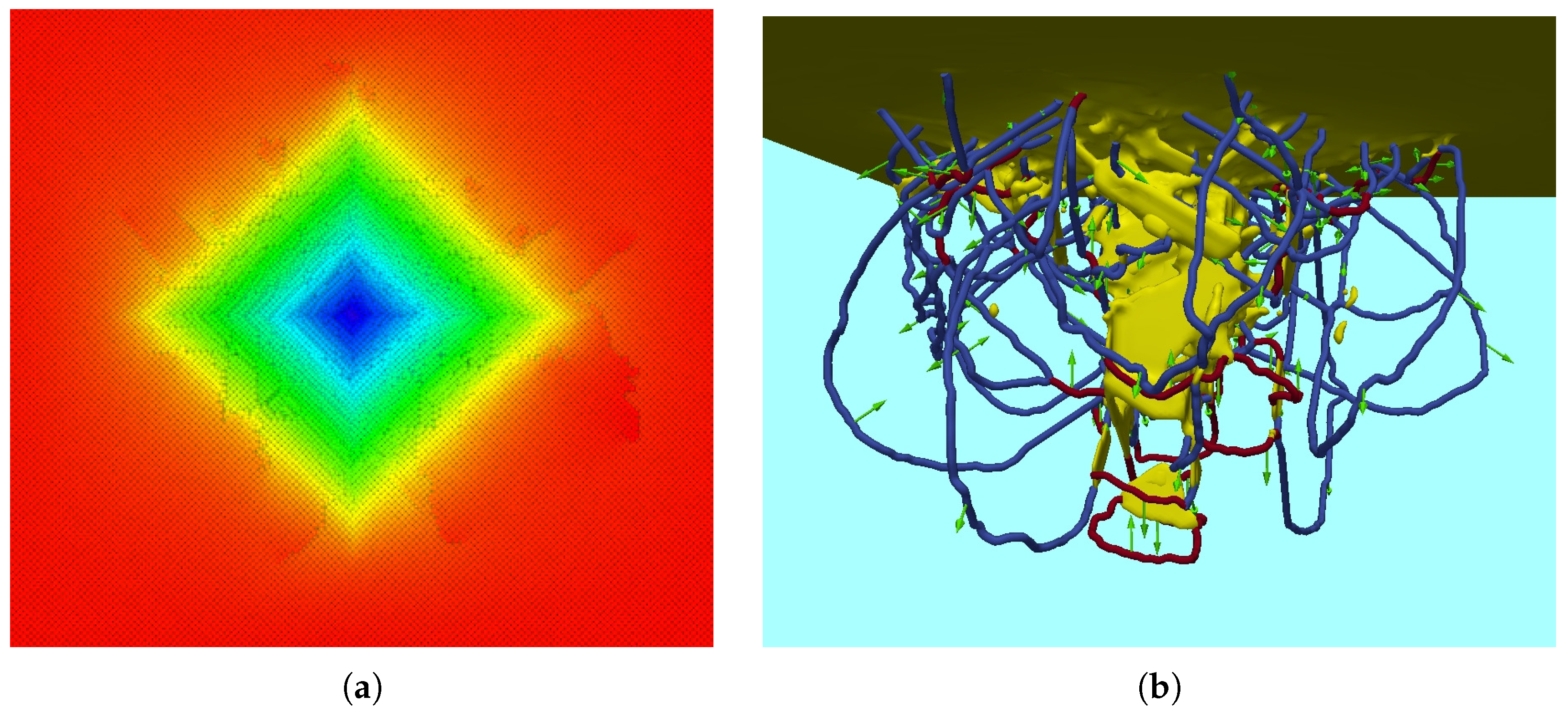
We exemplify the indentation with a Vickers indenter in Figure 4. Clearly, the imprint shape and surrounding pile-up reflect the shape of the Vickers indenter. On the other hand, the dense dislocation network developing below the surface is typical also of other indenter geometries with a large opening angle.
A more thorough study of the influence of the indenter shape was performed in [98] for the case of sc Fe. While this study focused on scratching, also the indentation process was included in the simulation. Systematic results could be obtained for indentation with a conical tip in dependence of the cone semi-apex angle . The indentation hardness increased with ; this feature could be rationalized by the increasing complexity of the dislocation network beneath the indenter. For the case of the Fe (100) surface studied, the hardness increase measured 30%, if changed from to .
The behavior of a Berkovich indenter agreed well with that of a cone with ; this angle agrees with the so-called equivalent cone angle of the Berkovich indenter [1,99]. The indentation behavior of a sphere shows, however, only poor agreement with the indentation of a cone with the corresponding equivalent cone angle, which in this case depends on the indentation depth. This missing agreement was attributed to the fact that cone and pyramid are self-similar structures, while the sphere is not.
6. Role of Adhesive Forces and Tip Wetting
Unlike in large-scale nanoindentation behavior, adhesion between indenter and substrate may play a significant role in nanocontact mechanics. Adhesion and tip wetting can be very pronounced at the nanoscale, with large surface area to volume ratio, clean surface and ultra high vacuum conditions. Molecular dynamics simulations of nanoindentation showed some of their potential in this area with the pioneering work of Landman et al. [14], showing metallic bonding and substrate-to-tip atom transfer (also known as the tip-wetting or jump-to-contact phenomenon) as a result of the need of optimization of the interaction energy. The high surface energies associated with clean metal surfaces can lead to strong attractive forces between surfaces close to contact, and these forces can become stronger in certain environmental conditions such as ultra-high vacuum. If the attraction is strong enough, surface atoms jump from the surface to the tip. Adhesion forces also play a role in retraction; as the tip retracts from the sample, a connective neck of atoms forms between the substrate and the tip. MD simulations also suggested that material transfer usually occurs during contact separation [30]. A similar phenomenon was found by Oliver et al. [100] when they performed one-to-one spatially matched experiment and atomistic simulations of nanometre-scale indentation; they reported that many features of the experiment were correctly reproduced by MD simulations, in some cases only when an atomically rough indenter rather than a smooth repulsive-potential indenter is used, tip wetting being one of these features. Paul et al. [101] highlighted the need to further explore the role of adhesive forces and tip wetting, ranging from the mechanisms of substrate-to-tip material transfer to electronic transport properties.
Tavazza et al. [102,103,104] used density-functional theory to study the details of the interaction of a diamond tip with a Ni surface. They found that the chemical interaction between the two materials leads to the formation of new ordered phases—comparable to a nickel carbide—at the contact area. This influences the substrate surface, but has also consequences for the wear of the tip, since substrate material is transferred to it. They argue that for the detailed investigation of such chemical changes quantum mechanical methods are necessary. In [102] this study is extended to oxidized and hydrogenated Ni surfaces; while O at the surface leads to similar results as a bare Ni surface, the presence of H reduces material transfer to the tip.
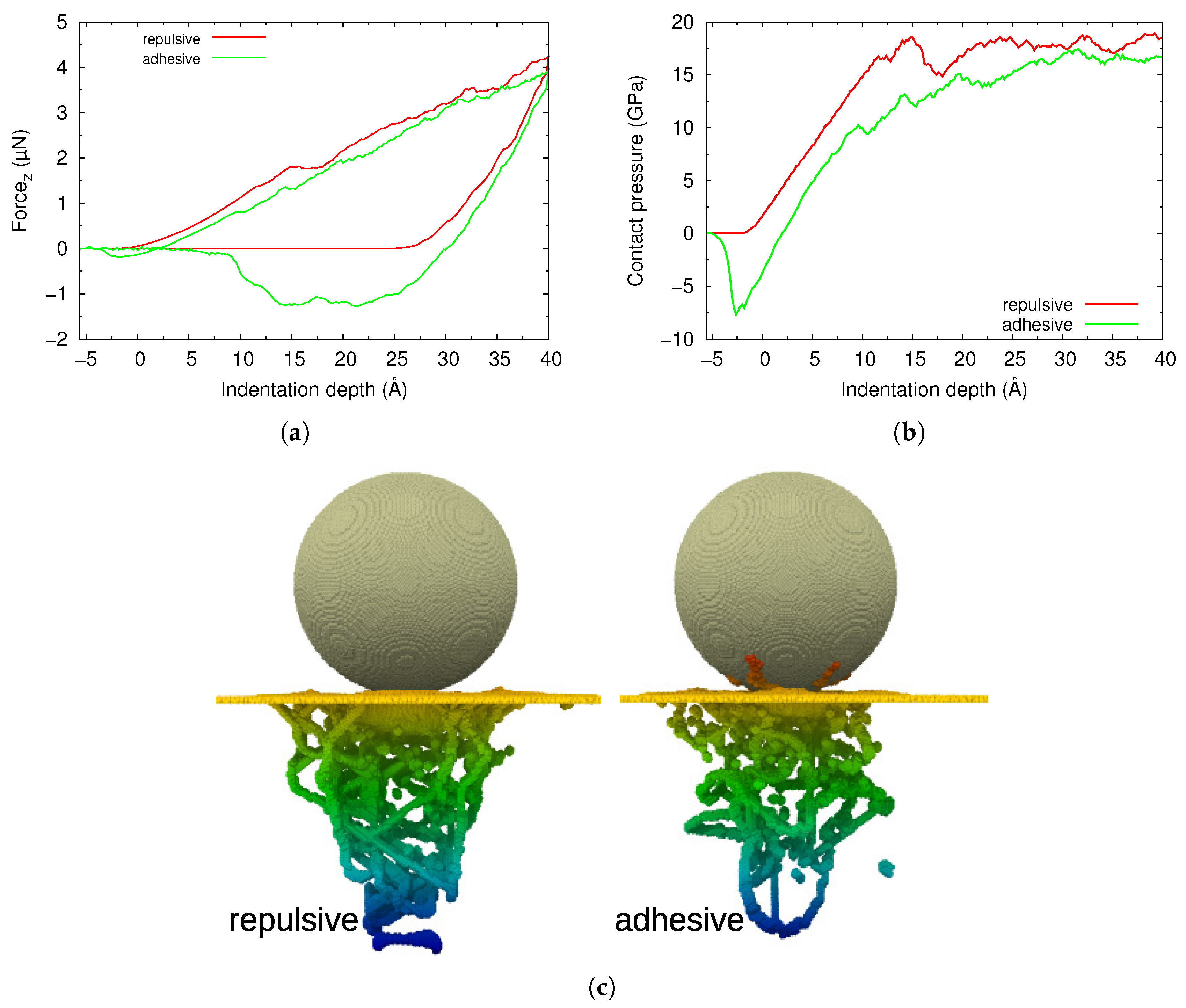
Figure 5 exemplifies the effect of adhesive forces between a diamond indenter (radius 10 nm) and an Fe (100) surface. A Morse potential with a well depth of 95 meV was assumed to act between C and Fe atoms [105]. We see that the indenter extracts some substrate material after retraction from the surface; this is identified by the red-colored atoms decorating the retracted tip. The pit size is smaller for the case of the adhesive interaction where the atoms move with the indenter upwards during unload.
The load-depth curve shows a clear minimum when the indenter approaches the surface due to the mutual attraction, and forces are lower than in the purely repulsive scenario during the entire indentation process. However, adhesive effects are even larger upon pit retraction. The final hardness—that is the contact pressure after full indentation—is, however, nearly the same in the repulsive and in the attractive case.
7. Conclusions
This report on recent results in the field of MD simulation of nanoindentation demonstrates the high level of activity in this field. Seemingly a simple process—a tip is pushed in a material leading to plastic deformation—still many details are unclear, and MD simulation seems a promising technique to further the understanding of this process. Of particular interest of the nanoindentation technique is its capability of creating localized plasticity.
Our review identified the fields in which further simulations efforts are required to advance our understanding of localized plasticity even further. While the effect of GBs and TBs on dislocation activity has already been studied to some extent [106], the response of nc metals and more generally defective materials—containing preexisting vacancies, dislocations, steps, ledges, etc.—needs further clarification. Also effects of surface roughness, nanostructured surfaces or of hard inclusions appear not to have been modeled up to now and requires clarification.
Acknowledgments
Iyad Alabd Alhafez and Herbert M. Urbassek acknowledge support by the Deutsche Forschungsgemeinschaft via the Sonderforschungsbereich 926. Carlos J. Ruestes acknowledges support by ANPCyT PICT-2015-0342, SECTyP UNCuyo and high performance computing resources at Mendieta CCAD-UNC through PDC-SNCAD MinCyT initiative.
Author Contributions
The authors contributed equally to this work.
Conflicts of Interest
The authors declare no conflict of interest.
Abbreviations
The following abbreviations are used in this manuscript:
| bcc | body centered cubic |
| fcc | face centered cubic |
| hcp | hexagonal close packed |
| nc | nanocrystalline |
| nt | nanotwinned |
| sc | single-crystalline |
| GB | grain boundary |
| MD | molecular dynamics |
| SFE | stacking fault energy |
| TB | twin boundary |
References
- Fischer-Cripps, A.C. Nanoindentation, 2nd ed.; Mechanical Engineering Series; Springer: New York, NY, USA, 2004. [Google Scholar]
- Armstrong, R.W.; Elban, W.L.; Walley, S.M. Elastic, Plastic, Cracking Aspects of the Hardness of Materials. Int. J. Mod. Phys. B 2013, 27, 1330004. [Google Scholar] [CrossRef]
- Weppelmann, E.; Wittling, M.; Swain, M.V.; Munz, D. Indentation Cracking of Brittle Thin Films on Brittle Substrates. In Fracture Mechanics of Ceramics; Bradt, R.C., Hasselman, D.P.H., Munz, D., Sakai, M., Shevchenko, V.Y., Eds.; Springer: Boston, MA, USA, 1996; pp. 475–486. [Google Scholar]
- Volinsky, A.A.; Vella, J.B.; Gerberich, W.W. Fracture toughness, adhesion and mechanical properties of low-K dielectric thin films measured by nanoindentation. Thin Solid Films 2003, 429, 201–210. [Google Scholar] [CrossRef]
- Yang, B.; Riester, L.; Nieh, T. Strain hardening and recovery in a bulk metallic glass under nanoindentation. Scr. Mater. 2006, 54, 1277–1280. [Google Scholar] [CrossRef]
- Bendavid, A.; Martin, P.; Takikawa, H. Deposition and modification of titanium dioxide thin films by filtered arc deposition. Thin Solid Films 2000, 360, 241–249. [Google Scholar] [CrossRef]
- Veprek, S. The search for novel, superhard materials. J. Vac. Sci. Technol. A Vac. Surf. Films 1999, 17, 2401–2420. [Google Scholar] [CrossRef]
- Cuy, J.L.; Mann, A.B.; Livi, K.J.; Teaford, M.F.; Weihs, T.P. Nanoindentation mapping of the mechanical properties of human molar tooth enamel. Arch. Oral Biol. 2002, 47, 281–291. [Google Scholar] [CrossRef]
- Oliver, W.C.; Pharr, G.M. An improved technique for determining hardness and elastic modulus using load and displacement sensing indentation experiments. J. Mater. Res. 1992, 7, 1564–1583. [Google Scholar] [CrossRef]
- Palacio, M.L.B.; Bhushan, B. Depth-sensing indentation of nanomaterials and nanostructures. Mater. Charact. 2013, 78, 1–20. [Google Scholar] [CrossRef]
- Luan, B.; Robbins, M.O. The breakdown of continuum models for mechanical contacts. Nature 2005, 435, 929. [Google Scholar] [CrossRef] [PubMed]
- Luan, B.; Robbins, M.O. Hybrid atomistic/continuum study of contact and friction between rough solids. Tribol. Lett. 2009, 36, 1–16. [Google Scholar] [CrossRef]
- Sinnott, S.B.; Heo, S.J.; Brenner, D.W.; Harrison, J.A.; Irving, D.L. Computer Simulations of Nanometer-Scale Indentation and Friction. In Springer Handbook of Nanotechnology; Springer: Berlin/Heidelberg, Germany, 2010; pp. 955–1011. [Google Scholar]
- Landman, U.; Luedtke, W.D.; Burnham, N.A.; Colton, R.J. Atomistic mechanisms and dynamics of adhesion, nanoindentation, and fracture. Science 1990, 248, 454–461. [Google Scholar] [CrossRef] [PubMed]
- Hoover, W.G.; De Groot, A.J.; Hoover, C.G.; Stowers, I.F.; Kawai, T.; Holian, B.L.; Boku, T.; Ihara, S.; Belak, J. Large-scale elastic-plastic indentation simulations via nonequilibrium molecular dynamics. Phys. Rev. A 1990, 42, 5844. [Google Scholar] [CrossRef] [PubMed]
- Harrison, J.A.; White, C.T.; Colton, R.J.; Brenner, D.W. Nanoscale investigation of indentation, adhesion and fracture of diamond (111) surfaces. Surf. Sci. 1992, 271, 57–67. [Google Scholar] [CrossRef]
- Sinnott, S.B.; Colton, R.J.; White, C.T.; Shenderova, O.A.; Brenner, D.W.; Harrison, J.A. Atomistic simulations of the nanometer-scale indentation of amorphous-carbon thin films. J. Vac. Sci. Technol. A Vac. Surf. Films 1997, 15, 936–940. [Google Scholar] [CrossRef]
- Kelchner, C.; Plimpton, S.; Hamilton, J. Dislocation nucleation and defect structure during surface indentation. Phys. Rev. B 1998, 58, 11085–11088. [Google Scholar] [CrossRef]
- Ruestes, C.J.; Bringa, E.M.; Gao, Y.; Urbassek, H.M. Molecular dynamics modeling of nanoindentation. In Applied Nanoindentation in Advanced Materials; Tiwari, A., Natarajan, S., Eds.; Wiley: Chichester, UK, 2017; Chapter 14; pp. 313–345. [Google Scholar]
- Van Vliet, K.; Li, J.; Zhu, T.; Yip, S.; Suresh, S. Quantifying the early stages of plasticity through nanoscale experiments and simulations. Phys. Rev. B 2003, 67, 104105. [Google Scholar] [CrossRef]
- Lee, Y.; Park, J.Y.; Kim, S.Y.; Jun, S.; Im, S. Atomistic simulations of incipient plasticity under Al (111) nanoindentation. Mech. Mater. 2005, 37, 1035–1048. [Google Scholar] [CrossRef]
- Zimmerman, J.A.; Kelchner, C.L.; Klein, P.A.; Hamilton, J.C.; Foiles, S.M. Surface Step Effects on Nanoindentation. Phys. Rev. Lett. 2001, 87, 165507. [Google Scholar] [CrossRef] [PubMed]
- Ziegenhain, G.; Urbassek, H.M. Effect of material stiffness on hardness: A computational study based on model potentials. Philos. Mag. 2009, 89, 2225–2238. [Google Scholar] [CrossRef]
- Ziegenhain, G.; Hartmaier, A.; Urbassek, H.M. Pair vs. many-body potentials: Influence on elastic and plastic behavior in nanoindentation of fcc metals. J. Mech. Phys. Solids 2009, 57, 1514–1526. [Google Scholar] [CrossRef]
- Ziegenhain, G.; Urbassek, H.M.; Hartmaier, A. Influence of crystal anisotropy on elastic deformation and onset of plasticity in nanoindentation: A simulational study. J. Appl. Phys. 2010, 107, 061807. [Google Scholar] [CrossRef]
- Gao, Y.; Ruestes, C.J.; Tramontina, D.R.; Urbassek, H.M. Comparative simulation study of the structure of the plastic zone produced by nanoindentation. J. Mech. Phys. Solids 2015, 75, 58–75. [Google Scholar] [CrossRef]
- Li, Y.; Goyal, A.; Chernatynskiy, A.; Jayashankar, J.S.; Kautzky, M.C.; Sinnott, S.B.; Phillpot, S.R. Nanoindentation of gold and gold alloys by molecular dynamics simulation. Mater. Sci. Eng. A 2016, 651, 346–357. [Google Scholar]
- Begau, C.; Hua, J.; Hartmaier, A. A novel approach to study dislocation density tensors and lattice rotation patterns in atomistic simulations. J. Mech. Phys. Solids 2012, 60, 711–722. [Google Scholar] [CrossRef]
- Yaghoobi, M.; Voyiadjis, G.Z. Atomistic simulation of size effects in single-crystalline metals of confined volumes during nanoindentation. Comput. Mater. Sci. 2016, 111, 64–73. [Google Scholar] [CrossRef]
- Hagelaar, J.H.A.; Bitzek, E.; Flipse, C.F.J.; Gumbsch, P. Atomistic simulations of the formation and destruction of nanoindentation contacts in tungsten. Phys. Rev. B 2006, 73, 045425. [Google Scholar] [CrossRef]
- Alcalá, J.; Dalmau, R.; Franke, O.; Biener, M.; Biener, J.; Hodge, A. Planar Defect Nucleation and Annihilation Mechanisms in Nanocontact Plasticity of Metal Surfaces. Phys. Rev. Lett. 2012, 109, 075502. [Google Scholar] [CrossRef] [PubMed]
- Remington, T.P.; Ruestes, C.J.; Bringa, E.M.; Remington, B.A.; Lu, C.H.; Kad, B.; Meyers, M.A. Plastic deformation in nanoindentation of tantalum: A new mechanism for prismatic loop formation. Acta Mater. 2014, 78, 378–393. [Google Scholar] [CrossRef]
- Ruestes, C.J.; Stukowski, A.; Tang, Y.; Tramontina, D.R.; Erhart, P.; Remington, B.A.; Urbassek, H.M.; Meyers, M.A.; Bringa, E.M. Atomistic simulation of tantalum nanoindentation: Effects of indenter diameter, penetration velocity, and interatomic potentials on defect mechanisms and evolution. Mater. Sci. Eng. A 2014, 613, 390–403. [Google Scholar] [CrossRef]
- Goel, S.; Beake, B.; Chan, C.W.; Faisal, N.H.; Dunne, N. Twinning anisotropy of tantalum during nanoindentation. Mater. Sci. Eng. A 2015, 627, 249–261. [Google Scholar] [CrossRef] [Green Version]
- Zambaldi, C.; Zehnder, C.; Raabe, D. Orientation dependent deformation by slip and twinning in magnesium during single crystal indentation. Acta Mater. 2015, 91, 267–288. [Google Scholar] [CrossRef]
- Sánchez-Martín, R.; Zambaldi, C.; Pérez-Prado, M.T.; Molina-Aldareguia, J.M. High temperature deformation mechanisms in pure magnesium studied by nanoindentation. Scr. Mater. 2015, 104, 9–12. [Google Scholar] [CrossRef]
- Somekawa, H.; Tsuru, T.; Singh, A.; Miura, S.; Schuh, C.A. Effect of crystal orientation on incipient plasticity during nanoindentation of magnesium. Acta Mater. 2017, 139, 21–29. [Google Scholar] [CrossRef]
- Lu, Z.; Chernatynskiy, A.; Noordhoek, M.J.; Sinnott, S.B.; Phillpot, S.R. Nanoindentation of Zr by Molecular Dynamics Simulation. J. Nucl. Mater. 2015, 467, 742–757. [Google Scholar]
- Alabd Alhafez, I.; Ruestes, C.J.; Gao, Y.; Urbassek, H.M. Nanoindentation of hcp metals: A comparative simulation study of the evolution of dislocation networks. Nanotechnology 2016, 27, 045706. [Google Scholar] [CrossRef] [PubMed]
- Kim, D.E.; Oh, S.I. Atomistic simulation of structural phase transformations in monocrystalline silicon induced by nanoindentation. Nanotechnology 2006, 17, 2259. [Google Scholar] [CrossRef]
- Mylvaganam, K.; Zhang, L.C.; Eyben, P.; Mody, J.; Vandervorst, W. Evolution of metastable phases in silicon during nanoindentation: mechanism analysis and experimental verification. Nanotechnology 2009, 20, 305705. [Google Scholar] [CrossRef] [PubMed]
- Goel, S.; Faisal, N.H.; Luo, X.; Yan, J.; Agrawal, A. Nanoindentation of polysilicon and single crystal silicon: Molecular dynamics simulation and experimental validation. J. Phys. D 2014, 47, 275304. [Google Scholar] [CrossRef]
- Du, X.; Zhao, H.; Zhang, L.; Yang, Y.; Xu, H.; Fu, H.; Li, L. Molecular dynamics investigations of mechanical behaviours in monocrystalline silicon due to nanoindentation at cryogenic temperatures and room temperature. Sci. Rep. 2015, 5, 16275. [Google Scholar] [CrossRef] [PubMed]
- Mylvaganam, K.; Zhang, L. Effect of crystal orientation on the formation of bct-5 silicon. Appl. Phys. A 2015, 120, 1391–1398. [Google Scholar] [CrossRef]
- Zhang, Z.; Stukowski, A.; Urbassek, H.M. Interplay of dislocation-based plasticity and phase transformation during Si nanoindentation. Comput. Mater. Sci. 2016, 119, 82–89. [Google Scholar] [CrossRef]
- Zhang, Z.; Urbassek, H.M. Comparative study of interatomic interaction potentials for describing indentation into Si using molecular dynamics simulation. Appl. Mech. Mater. 2017, 869, 3–8. [Google Scholar] [CrossRef]
- Zhang, J.; Zhang, J.; Wang, Z.; Hartmaier, A.; Yan, Y.; Sun, T. Interaction between phase transformations and dislocations at incipient plasticity of monocrystalline silicon under nanoindentation. Comput. Mater. Sci. 2017, 131, 55–61. [Google Scholar] [CrossRef]
- Abram, R.; Chrobak, D.; Nowak, R. Origin of a Nanoindentation Pop-in Event in Silicon Crystal. Phys. Rev. Lett. 2017, 118, 095502. [Google Scholar] [CrossRef] [PubMed]
- Stillinger, F.H.; Weber, T.A. Computer simulation of local order in condensed phases of Si. Phys. Rev. B 1985, 31, 5262–5271. [Google Scholar] [CrossRef]
- Tersoff, J. New emprirical approach for the structure and energy of covalent systems. Phys. Rev. B 1988, 37, 6991. [Google Scholar] [CrossRef]
- Chrobak, D.; Kim, K.H.; Kurzydlowski, K.J.; Nowak, R. Nanoindentation experiments with different loading rate distinguish the mechanism of incipient plasticity. Appl. Phys. Lett. 2013, 103, 072101. [Google Scholar] [CrossRef]
- Chrobak, D.; Tymiak, N.; Beaber, A.; Ugurlu, O.; Gerberich, W.W.; Nowak, R. Deconfinement leads to changes in the nanoscale plasticity of silicon. Nat. Nanotechnol. 2011, 6, 480–484. [Google Scholar] [CrossRef] [PubMed]
- Goel, S.; Luo, X.; Agrawal, A.; Reuben, R.L. Diamond machining of silicon: A review of advances in molecular dynamics simulation. Int. J. Mach. Tools Manuf. 2015, 88, 131–164. [Google Scholar] [CrossRef]
- Erhart, P.; Albe, K. Analytical potential for atomistic simulations of silicon, carbon, and silicon carbide. Phys. Rev. B 2005, 71, 035211. [Google Scholar] [CrossRef]
- Richter, A.; Ries, R.; Smith, R.; Henkel, M.; Wolf, B. Nanoindentation of diamond, graphite and fullerene films. Diam. Relat. Mater. 2000, 9, 170–184. [Google Scholar] [CrossRef]
- Szlufarska, I.; Nakano, A.; Vashishta, P. A crossover in the mechanical response of nanocrystalline ceramics. Science 2005, 309, 911–914. [Google Scholar] [CrossRef] [PubMed]
- Walsh, P.; Kalia, R.K.; Nakano, A.; Vashishta, P.; Saini, S. Amorphization and anisotropic fracture dynamics during nanoindentation of silicon nitride: A multimillion atom molecular dynamics study. Appl. Phys. Lett. 2000, 77, 4332–4334. [Google Scholar] [CrossRef]
- Chen, Y.C.; Nomura, K.I.; Kalia, R.K.; Nakano, A.; Vashishta, P. Molecular dynamics nanoindentation simulation of an energetic material. Appl. Phys. Lett. 2008, 93, 171908. [Google Scholar] [CrossRef]
- Imran, M.; Hussain, F.; Rashid, M.; Cai, Y.; Ahmad, S.A. Mechanical behavior of Cu-Zr bulk metallic glasses (BMGs): A molecular dynamics approach. Chin. Phys. B 2013, 22, 096101. [Google Scholar] [CrossRef]
- Qiu, C.; Zhu, P.; Fang, F.; Yuan, D.; Shen, X. Study of nanoindentation behavior of amorphous alloy using molecular dynamics. Appl. Surf. Sci. 2014, 305, 101–110. [Google Scholar] [CrossRef]
- Zhao, D.; Zhao, H.; Zhu, B.; Wang, S. Investigation on hardening behavior of metallic glass under cyclic indentation loading via molecular dynamics simulation. Appl. Surf. Sci. 2017, 416, 14–23. [Google Scholar] [CrossRef]
- Feng, Q.; Song, X.; Xie, H.; Wang, H.; Liu, X.; Yin, F. Deformation and plastic coordination in WC-Co composite—Molecular dynamics simulation of nanoindentation. Mater. Des. 2017, 120, 193–203. [Google Scholar] [CrossRef]
- Zhang, Z.; Urbassek, H.M. Indentation into an Al/Si composite: Enhanced dislocation mobility at interface. J. Mater. Sci. 2017, 1–15. [Google Scholar] [CrossRef]
- Li, J.; Fang, Q.; Liu, B.; Liu, Y.; Liu, Y. Atomic-scale analysis of nanoindentation behavior of high-entropy alloy. J. Micromech. Mol. Phys. 2016, 1, 1650001. [Google Scholar] [CrossRef]
- Zhao, Y.; Peng, X.; Fu, T.; Huang, C.; Feng, C.; Yin, D.; Wang, Z. Molecular dynamics simulation of nano-indentation of (111) cubic boron nitride with optimized Tersoff potential. Appl. Surf. Sci. 2016, 382, 309–315. [Google Scholar] [CrossRef]
- Xu, S.; Wan, Q.; Sha, Z.; Liu, Z. Molecular dynamics simulations of nano-indentation and wear of the gamma-Ti-Al alloy. Comput. Mater. Sci. 2015, 110, 247–253. [Google Scholar] [CrossRef]
- Javaid, F.; Stukowski, A.; Durst, K. 3D Dislocation structure evolution in strontium titanate: Spherical indentation experiments and MD simulations. J. Am. Ceram. Soc. 2017, 100, 1134–1145. [Google Scholar] [CrossRef]
- Van Swygenhoven, H.; Derlet, P.M.; Hasnaoui, A. Atomic mechanism for dislocation emission from nanosized grain boundaries. Phys. Rev. B 2002, 66, 024101. [Google Scholar] [CrossRef]
- Van Vliet, K.J.; Tsikata, S.; Suresh, S. Model experiments for direct visualization of grain boundary deformation in nanocrystalline metals. Appl. Phys. Lett. 2003, 83, 1441–1443. [Google Scholar] [CrossRef]
- Feichtinger, D.; Derlet, P.M.; Van Swygenhoven, H. Atomistic simulations of spherical indentations in nanocrystalline gold. Phys. Rev. B 2003, 67, 024113. [Google Scholar] [CrossRef]
- Ma, X.L.; Yang, W. Molecular dynamics simulation on burst and arrest of stacking faults in nanocrystalline Cu under nanoindentation. Nanotechnology 2003, 14, 1208. [Google Scholar] [CrossRef]
- Hasnaoui, A.; Derlet, P.M.; Van Swygenhoven, H. Interaction between dislocations and grain boundaries under an indenter–a molecular dynamics simulation. Acta Mater. 2004, 52, 2251–2258. [Google Scholar] [CrossRef]
- Jang, H.; Farkas, D. Interaction of lattice dislocations with a grain boundary during nanoindentation simulation. Mater. Lett. 2007, 61, 868–871. [Google Scholar] [CrossRef]
- Liu, X.; Yuan, F.; Wei, Y. Grain size effect on the hardness of nanocrystal measured by the nanosize indenter. Appl. Surf. Sci. 2013, 279, 159–166. [Google Scholar] [CrossRef]
- Huang, C.C.; Chiang, T.C.; Fang, T.H. Grain size effect on indentation of nanocrystalline copper. Appl. Surf. Sci. 2015, 353, 494–498. [Google Scholar] [CrossRef]
- Li, J.; Guo, J.; Luo, H.; Fang, Q.; Wu, H.; Zhang, L.; Liu, Y. Study of nanoindentation mechanical response of nanocrystalline structures using molecular dynamics simulations. Appl. Surf. Sci. 2016, 364, 190–200. [Google Scholar] [CrossRef]
- Voyiadjis, G.Z.; Yaghoobi, M. Role of grain boundary on the sources of size effects. Comput. Mater. Sci. 2016, 117, 315–329. [Google Scholar] [CrossRef]
- Guleryuz, E.; Mesarovic, S.D. Dislocation nucleation on grain boundaries: Low angle twist and asymmetric tilt boundaries. Crystals 2016, 6, 77. [Google Scholar] [CrossRef]
- Talaei, M.S.; Nouri, N.; Ziaei-Rad, S. Grain boundary effects on nanoindentation of Fe bicrystal using molecular dynamic. Mech. Mater. 2016, 102, 97–107. [Google Scholar] [CrossRef]
- Dupont, V.; Sansoz, F. Grain Boundary Structure Evolution in Nanocrystalline Al by Nanoindentation Simulations. MRS Online Proc. Libr. Arch. 2005, 903, 0903–Z06–05. [Google Scholar] [CrossRef]
- Faghihi, D.; Voyiadjis, G.Z. Determination of nanoindentation size effects and variable material intrinsic length scale for body-centered cubic metals. Mech. Mater. 2012, 44, 189–211. [Google Scholar] [CrossRef]
- Esqué-de los Ojos, D.; Pellicer, E.; Sort, J. The Influence of Pore Size on the Indentation Behavior of Metallic Nanoporous Materials: A Molecular Dynamics Study. Materials 2016, 9, 355. [Google Scholar] [CrossRef] [PubMed]
- Ukwatta, A.; Achuthan, A. A molecular dynamics (MD) simulation study to investigate the role of existing dislocations on the incipient plasticity under nanoindentation. Comput. Mater. Sci. 2014, 91, 329–338. [Google Scholar] [CrossRef]
- Ziegenhain, G.; Urbassek, H.M. Nanostructured surfaces yield earlier: Molecular dynamics study of nanoindentation into adatom islands. Phys. Rev. B 2010, 81, 155456. [Google Scholar] [CrossRef]
- Van Vliet, K.J.; Suresh, S. Simulations of cyclic normal indentation of crystal surfaces using the bubble-raft model. Philos. Mag. A 2002, 82, 1993–2001. [Google Scholar] [CrossRef]
- Gouldstone, A.; Van Vliet, K.J.; Suresh, S. Nanoindentation: Simulation of defect nucleation in a crystal. Nature 2001, 411, 656. [Google Scholar] [CrossRef] [PubMed]
- Zarudi, I.; Zhang, L.C.; Swain, M.V. Microstructure evolution in monocrystalline silicon in cyclic microindentations. J. Mater. Res. 2003, 18, 758–761. [Google Scholar] [CrossRef]
- Komvopoulos, K.; Yan, W. Molecular dynamics simulation of single and repeated indentation. J. Appl. Phys. 1997, 82, 4823–4830. [Google Scholar] [CrossRef]
- Cheong, W.C.D.; Zhang, L. Effect of repeated nano-indentations on the deformation in monocrystalline silicon. J. Mater. Sci. Lett. 2000, 19, 439–442. [Google Scholar] [CrossRef]
- Shiari, B.; Miller, R.E. Multiscale modeling of ductile crystals at the nanoscale subjected to cyclic indentation. Acta Mater. 2008, 56, 2799–2809. [Google Scholar] [CrossRef]
- Cordill, M.J.; Lund, M.S.; Parker, J.; Leighton, C.; Nair, A.K.; Farkas, D.; Moody, N.R.; Gerberich, W.W. The Nano-Jackhammer effect in probing near-surface mechanical properties. Int. J. Plast. 2009, 25, 2045–2058. [Google Scholar] [CrossRef]
- Deng, C.; Schuh, C.A. Atomistic mechanisms of cyclic hardening in metallic glass. Appl. Phys. Lett. 2012, 100, 251909. [Google Scholar] [CrossRef]
- Imran, M.; Hussain, F.; Rashid, M.; Ahmad, S.A. Dynamic characteristics of nanoindentation in Ni: A molecular dynamics simulation study. Chin. Phys. B 2012, 21, 116201. [Google Scholar] [CrossRef]
- Salehinia, I.; Wang, J.; Bahr, D.F.; Zbib, H.M. Molecular dynamics simulations of plastic deformation in Nb/NbC multilayers. Int. J. Plast. 2014, 59, 119–132. [Google Scholar] [CrossRef]
- Wang, N.; Yan, F.; Li, L. Mesoscopic examination of cyclic hardening in metallic glass. J. Non-Cryst. Solids 2015, 428, 146–150. [Google Scholar] [CrossRef]
- Göring, G.; Dietrich, P.I.; Blaicher, M.; Sharma, S.; Korvink, J.G.; Schimmel, T.; Koos, C.; Hölscher, H. Tailored probes for atomic force microscopy fabricated by two-photon polymerization. Appl. Phys. Lett. 2016, 109, 063101. [Google Scholar] [CrossRef]
- Commercial Diamond Tips from SCD Probe (D300 Series). Available online: www.scdprobes.com/D300.pdf (accessed on 5 September 2017).
- Alabd Alhafez, I.; Brodyanski, A.; Kopnarski, M.; Urbassek, H.M. Influence of Tip Geometry on Nanoscratching. Tribol. Lett. 2017, 65, 26. [Google Scholar] [CrossRef]
- Fischer-Cripps, A.C. Critical review of analysis and interpretation of nanoindentation test data. Surf. Coat. Technol. 2006, 200, 4153–4165. [Google Scholar] [CrossRef]
- Oliver, D.J.; Paul, W.; El Ouali, M.; Hagedorn, T.; Miyahara, Y.; Qi, Y.; Grütter, P.H. One-to-one spatially matched experiment and atomistic simulations of nanometre-scale indentation. Nanotechnology 2013, 25, 025701. [Google Scholar] [CrossRef] [PubMed]
- Paul, W.; Oliver, D.; Grütter, P. Indentation-formed nanocontacts: An atomic-scale perspective. Phys. Chem. Chem. Phys. 2014, 16, 8201–8222. [Google Scholar] [CrossRef] [PubMed]
- Tavazza, F.; Senftle, T.P.; Zou, C.; Becker, C.A.; van Duin, A.C.T. Molecular Dynamics Investigation of the Effects of Tip-Substrate Interactions during Nanoindentation. J. Phys. Chem. C 2015, 119, 13580–13589. [Google Scholar] [CrossRef]
- Tavazza, F.; Levine, L.E. DFT Investigation of Early Stages of Nanoindentation in Ni. J. Phys. Chem. C 2016, 120, 13249–13255. [Google Scholar] [CrossRef]
- Tavazza, F.; Kuhr, B.; Farkas, D.; Levine, L.E. Ni Nanoindentation at the Nanoscale: Atomic Rearrangements at the Ni-C Interface. J. Phys. Chem. C 2017, 121, 2643–2651. [Google Scholar] [CrossRef]
- Gao, Y.F.; Yang, Y.; Sun, D.Y. Wetting of Liquid Iron in Carbon Nanotubes and on Graphene Sheets: A Molecular Dynamics Study. Chem. Phys. Lett. 2011, 28, 036102. [Google Scholar] [CrossRef]
- Spearot, D.E.; Sangid, M.D. Insights on slip transmission at grain boundaries from atomistic simulations. Curr. Opin. Solid State Mater. Sci. 2014, 18, 188–195. [Google Scholar] [CrossRef]
Figure 1.
Prismatic loop formation in bcc Ta, see text. Original contribution of the authors.

Figure 2.
Dislocation networks generated for indentation into Ti. (a) Basal plane, (b) first prismatic plane, (c) second prismatic plane. Dislocations with Burgers vector are colored dark red, orange, white, and blue. The deformed surface and other defects are colored yellow. Original contribution of the authors.

Figure 3.
Sequence of indentation and release in a Fe sample with pre-existing defects, see text. Original contribution of the authors.
Figure 3.
Sequence of indentation and release in a Fe sample with pre-existing defects, see text. Original contribution of the authors.
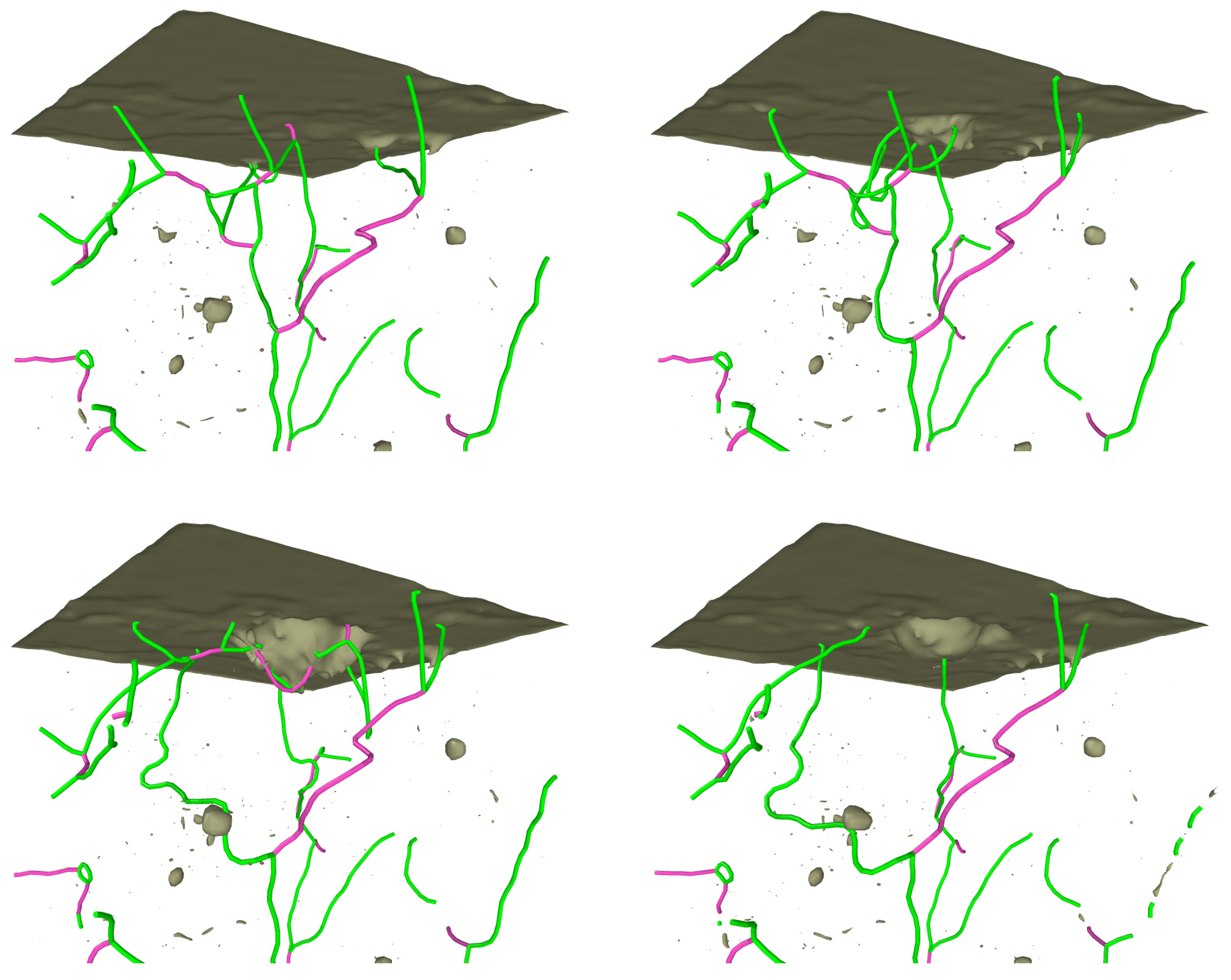
Figure 4.
Indentation with a Vickers indenter into an Fe (100) surface. (a) Indent pit. (b) Dislocation network. Original contribution of the authors.
Figure 4.
Indentation with a Vickers indenter into an Fe (100) surface. (a) Indent pit. (b) Dislocation network. Original contribution of the authors.

Figure 5.
Comparison of indentation with a repulsive and an attractive diamond indenter into a Fe (100) surface. (a) Load-depth curve. (b) Contact pressure. (c) Pile-up after retraction of the indenter. Original contribution of the authors.
Figure 5.
Comparison of indentation with a repulsive and an attractive diamond indenter into a Fe (100) surface. (a) Load-depth curve. (b) Contact pressure. (c) Pile-up after retraction of the indenter. Original contribution of the authors.
© 2017 by the authors. Licensee MDPI, Basel, Switzerland. This article is an open access article distributed under the terms and conditions of the Creative Commons Attribution (CC BY) license (http://creativecommons.org/licenses/by/4.0/).
Share and Cite
MDPI and ACS Style
Ruestes, C.J.; Alhafez, I.A.; Urbassek, H.M. Atomistic Studies of Nanoindentation—A Review of Recent Advances. Crystals 2017, 7, 293. https://doi.org/10.3390/cryst7100293
AMA Style
Ruestes CJ, Alhafez IA, Urbassek HM. Atomistic Studies of Nanoindentation—A Review of Recent Advances. Crystals. 2017; 7(10):293. https://doi.org/10.3390/cryst7100293
Chicago/Turabian StyleRuestes, Carlos J., Iyad Alabd Alhafez, and Herbert M. Urbassek. 2017. "Atomistic Studies of Nanoindentation—A Review of Recent Advances" Crystals 7, no. 10: 293. https://doi.org/10.3390/cryst7100293
Note that from the first issue of 2016, this journal uses article numbers instead of page numbers. See further details here.