
Persistence of Smectic-A Oily Streaks into the Nematic Phase by UV Irradiation of Reactive Mesogens
by

Ines Gharbi
1,2, 
Amine Missaoui
2,
Dominique Demaille
2,
Emmanuelle Lacaze
2,3 and
Charles Rosenblatt
3,*
1
LR99ES16 Laboratoire Physique de la Matière Molle et de la Modélisation Électromagnétique, Faculté des Sciences de Tunis, Université de Tunis El Manar, 2092 Tunis, Tunisia
2
Institut des Nano-Sciences de Paris (INSP), CNRS UMR 7588, UPMC Univ Paris 06, Sorbonne Université, F75005 Paris, France
3
Department of Physics, Case Western Reserve University, Cleveland, OH 44106, USA
*
Author to whom correspondence should be addressed.
Crystals 2017, 7(12), 358; https://doi.org/10.3390/cryst7120358
Submission received: 27 September 2017
/
Revised: 26 November 2017
/
Accepted: 30 November 2017
/
Published: 3 December 2017
(This article belongs to the Section Liquid Crystals)
Abstract
:Thin smectic liquid crystal films with competing boundary conditions (planar and homeotropic at opposing surfaces) form well-known striated structures known as “oily streaks”, which are a series of hemicylindrical caps that run perpendicular to the easy axis of the planar substrate. The streaks vanish on heating into the nematic phase, where the film becomes uniform and exhibits hybrid alignment. On adding sufficient reactive mesogen and polymerizing, the oily streak texture is maintained on heating through the entire nematic phase until reaching the bulk isotropic phase, above which the texture vanishes. Depending on the liquid crystal thickness, the oily streak structure may be retrieved after cooling, which demonstrates the strong impact of the polymer backbone on the liquid crystal texture. Polarizing optical, atomic force, and scanning electron microscopy data are presented.
1. Introduction
Polymer-stabilized liquid crystals (PSLCs) have piqued the interest of researchers since their first demonstration in the 1990s [1,2,3,4]. In the last few years there have been remarkable developments in the field of PSLCs, both at the academic level and for advanced applications such as photonics [5,6], three-dimensional (3-D) displays, light modulators, fast-response optical switches [7], smart windows (switching between highly transparent and opaque states) and, for the most flexible substrates, as sensors and actuators because of their high degree of bending deformability [8,9,10,11]. For an appropriate reactive mesogen, the polymer assumes the same basic structure as that of the liquid crystal (LC) [12,13]. Thus, the specific liquid crystal structure can be frozen-in, becoming rigid and relatively insensitive to external fields and temperature variations. There exist several methods [14] by which one can induce in situ polymerization, including thermal polymerization, polymerization by mixing several components, and polymerization by UV radiation. The latter is the most commonly used due to its high degree of polymerization and the ability to define the moment of polymerization onset [14]. The polymerization reaction is carried out in three steps: The photoinitiator is excited by UV light and thus produces radicals. These radicals then react with monomers, producing new radicals, which then react themselves to form polymer chains. As the polymerization proceeds, the miscible and homogeneous liquid crystalline phase become phase-separated [15]. The UV-exposed surface polymerizes first due to the limited penetrability of UV light in the mixture. The structure of the phase separation [2], and therefore the homogeneity of the polymer network within the entire film [16], can be controlled by varying the composition of the mixture, the thickness of the samples, the intensity of the polymerizing lamp, and the exposure time [2,17]. These parameters play an essential role in the flexibility and rigidity of films, thus diversifying their applications.
Not only can the liquid crystal structures be frozen-in by polymerization, but the polymerized matrix also can block entrapped impurities such as particles [5,18]. It has been shown that a network of particles polymerized in a nematic matrix can be stored up to a temperature above 150 °C while the surrounding liquid crystal system transitions to the isotropic state [6]. This occurs because there are two transition temperatures: the nematic—isotropic transition associated with the confined nematic liquid crystal inside the polymer backbone, and the disordering polymer transition. The nanoparticle assembly is frozen-in by the polymerized matrix, independent of the nematic–isotropic transition, which itself is increased from 35 °C to ~65 °C in the presence of nanoparticles and the polymerized matrix.
Liquid crystal polymerization thus facilitates the stabilization of nanoparticle networks, initially induced by the liquid crystal textures. Pioneering work on vitrified cholesteric liquid crystals containing metallic nanoparticles showed their trapping by the disclination lines of a stripe texture [19,20]. Owing to the high efficiency of nanoparticle (NP) trapping by liquid crystalline topological defects [21,22,23,24,25,26], it is both interesting and potentially useful to understand how liquid crystalline structures with topological defects can be polymerized. This is particularly appropriate for the so-called smectic oily streaks, which are found in extremely thin (100 < h < 500 nm, where h is the film thickness) open films and which consist of a dense array of linear topological defects, in particular smectic dislocations that are oriented perpendicular to the substrate rubbing, in conjunction with the presence of a rotating grain boundary that replaces the smectic layers close to the center of curvature [27]. In order to match the competing boundary conditions—the director is parallel to the substrate’s easy axis over most or all of the alignment layer and is perpendicular at the air interface—the smectic layers deform into a series of hemicylinders (Figure 1b), resulting in the texture observed under a polarizing microscope seen in Figure 1a. Given this structure, oily streaks are able to organize nanoparticles in single chains with strongly anisotropic optical properties [22,23,24,26].
In this work we present a method to stabilize the oily streaks in the smectic-A (Sm-A) phase. Using a 450-nm thick film, we examine the concentrations of reactive mesogen (for 3, 7, and 10 wt % of monomer) to determine the concentration that facilitates polymerization while maintaining the oily streak structure at elevated temperatures. We determine the nematic—Sm-A transition temperature for each concentration. We study the evolution of the polymerized skeleton with temperature in order to determine the limiting temperature at which the polymerized oily streaks disappear, and then reduce the temperature to examine the robustness of the just-heated liquid crystal/polymer network. Using atomic force microscopy, we show that the polymerized oily streak topography at the air interface remains robust even after more than one year post polymerization. We then irradiate a thin film (200 nm) in order to understand thickness and temperature effects on the robustness of the skeletal structure after a heating and cooling cycle.
Our central result is that for a sufficiently high concentration of reactive mesogen and appropriate film thickness, a polymer backbone is created that mimics the hemicylindrical oily streak structure. As a result, not only does the oily streak texture remain stable in Sm-A phase in the presence of the polymer backbone, but the oily streak texture also could be stabilized at temperatures corresponding to the nematic phase of the bulk liquid crystal. Depending on the degree of polymerization, when the sample is heated above the nematic—isotropic phase transition temperature TNI and cooled back into the nematic phase, the oily streaks will reappear reversibly or will be destroyed irreversibly.
2. Results
Sample preparation, optical microscopy, atomic force microscopy, and scanning electron microscopy measurements of the topography appear in Section 4, Materials and Methods.
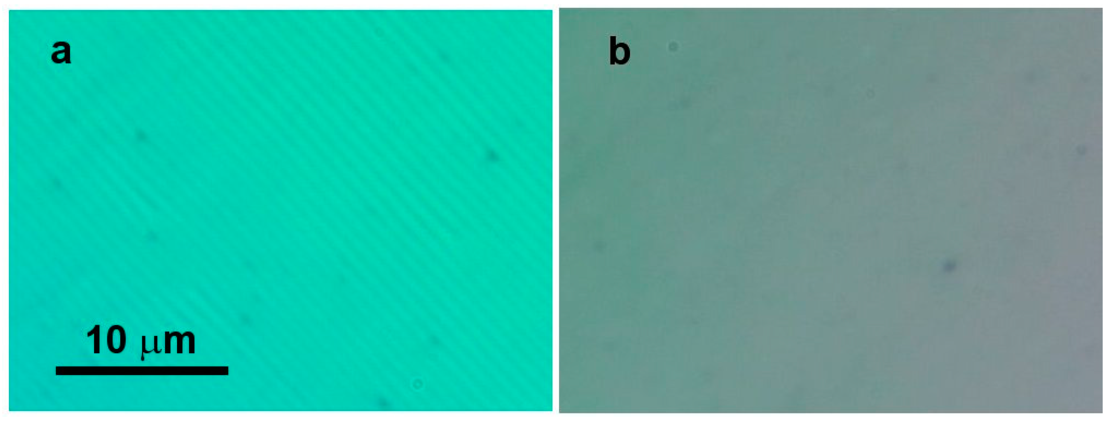
Figure 2 shows images of the 8CB liquid crystal thick film (450 nm) doped with 3 wt % reactive mesogen plus initiator, after irradiation with a lamp of power 0.15 mW cm−2. The same picture was obtained before irradiation with no variation of the transition temperature, suggesting that the polymerization was not successful in freezing-in the oily streaks. The only notable difference between the 3 wt % and pure samples was a decrease of TNA of approximately 1 °C, which applies to both polymerized and unpolymerized 3 wt % films. Figure 2a shows the film in the Sm-A phase at 29.5 °C, with the closely spaced oily streaks being punctuated by wider streaks, a structure that still is under investigation. Figure 2b shows the same region at 31 °C after heating above the Sm-A—nematic phase transition temperature at TNA ~30 °C. Notice that both the oily streaks and the wide streaks have vanished in the nematic phase, despite the presence of a rarefied skeletal structure.
A general observation is that TNA decreases with increasing reactive mesogen concentration, at least up to 10 wt %. This is shown for a 10 wt % non-UV-irradiated thick (450 nm) film where the oily streaks vanish at approximately 24.5 °C on heating (Figure 3a,b). Above 24.5 °C, the film is a well-aligned hybrid nematic, with an approximately planar alignment at the substrate and homeotropic alignment at the air interface. Thus, we found that TNA decreased from 33 °C for pure 8CB to 30 °C for 3% of monomers and to 24.5 °C for 7 and 10 wt % of reactive mesogen.
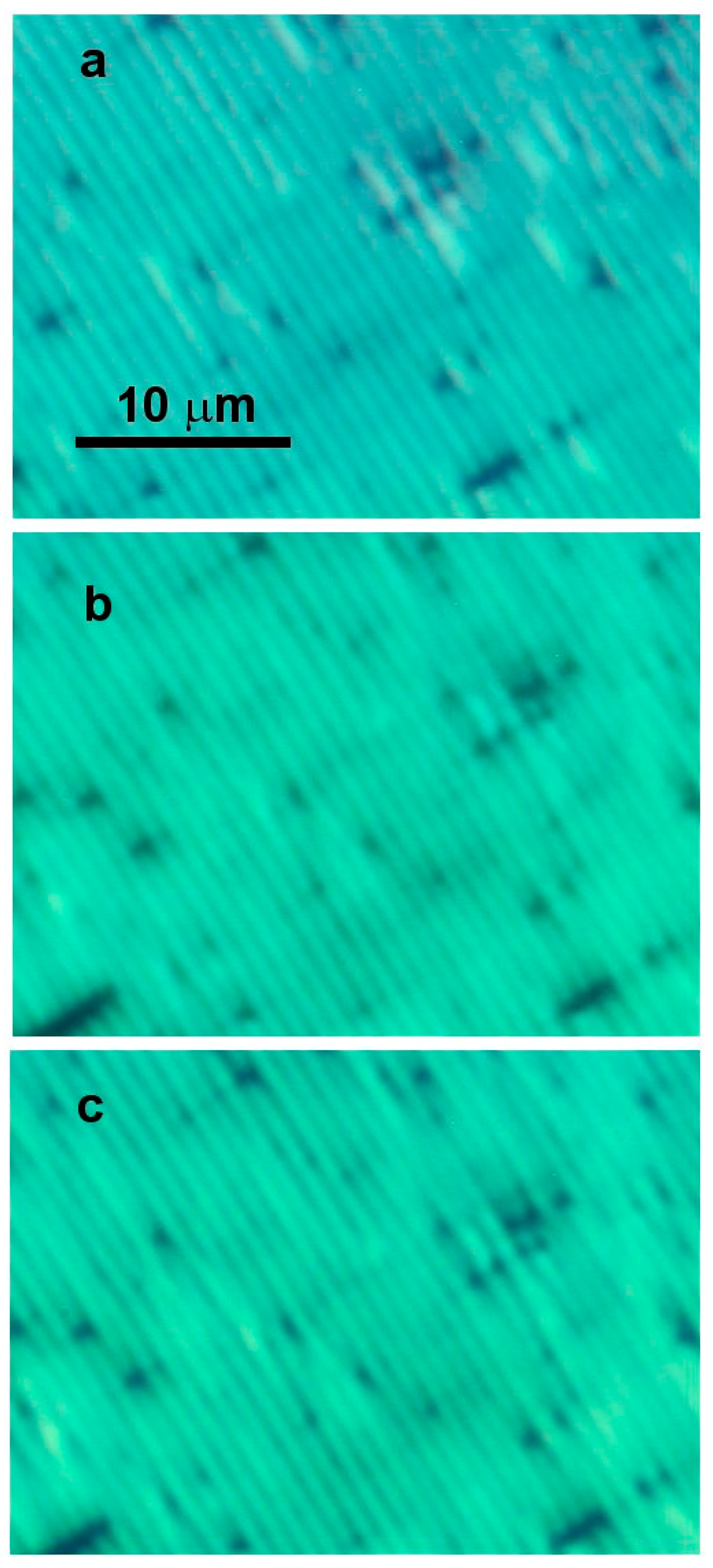
Figure 4 shows images of the 7 wt % thick film after UV irradiation with the lamp intensity of 0.15 mW cm−2. Figure 4a shows the streaks at 27 °C, inside the Sm-A phase. The oily streaks are sharp and well defined. At 28.5 °C one observes a change in the oily streaks’ appearance (Figure 4b), as they become slightly ragged and show contrast variations running along the length of the streaks. At 30 °C this raggedness increases only slightly, as seen in Figure 4c. The appearance of these textures is approximately constant over the temperature range from 23 °C through 28 °C, and again above 29 °C. For the polymerized reactive mesogen, the apparent transition from the Sm-A to the nematic phase occurs at 28.5 °C, above which the oily streaks remain, unlike the case for the 3 wt % film.
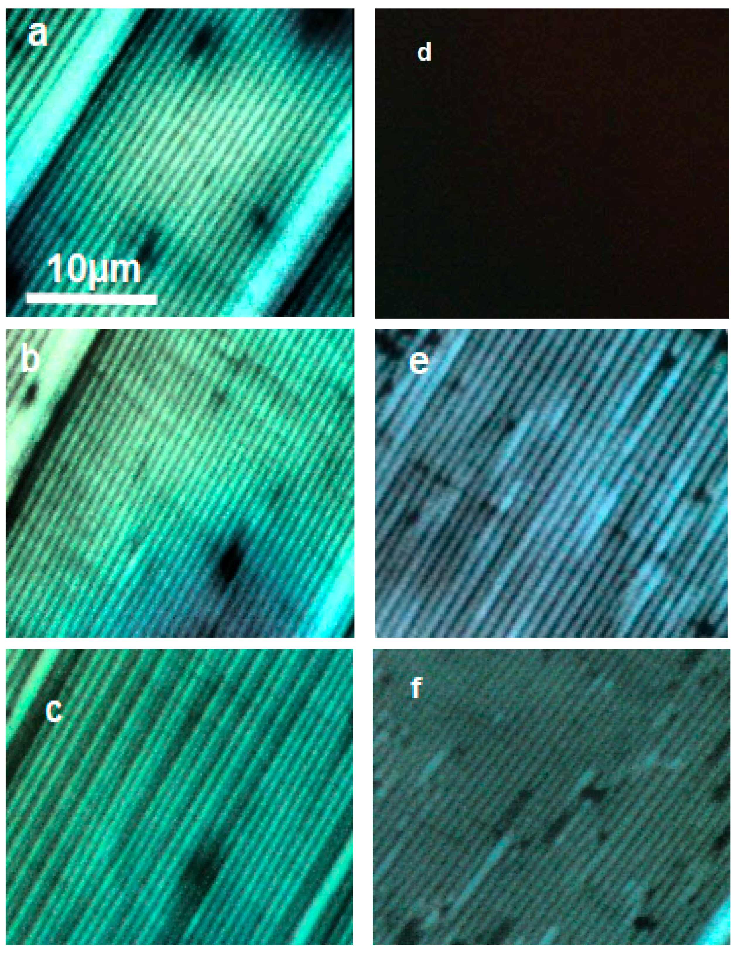
This behavior is even more apparent in the 10 wt % thick film images. Figure 5 shows the behavior of the 450-nm film after irradiation. At low temperatures, in the Sm-A phase, well-defined oily streaks are present (Figure 5a). As is the case for the 7 wt % thick film, the oily streaks remain intact but are more ragged above the nematic—Sm-A transition, as seen in in Figure 5b. Figure 5c shows the oily streaks becoming dimmer and less well-defined—but still clearly oily streaks—at 37 °C. Nematic—isotropic phase separation occurs from approximately 41 °C to 41.5 °C, and Figure 5d shows the film in the isotropic phase. Here the film appears uniformly dark under crossed polarizers, as would occur in an isotropic phase. After heating the liquid crystal at 54 °C, the oily streak texture did not reappear on cooling back into the nematic and Sm-A phases. Instead, an array of ill-defined and aperiodic wider striations parallel to the original oily streaks in a dark background appeared at approximately 41.5 °C, the structure of which remained stable down to at least 19 °C (Figure 5e,f). Heating into the isotropic phase clearly resulted in an irreversible disruption of the oily streak texture. Another sample was created, but this time heated only slightly into the isotropic phase, to 42 °C. On cooling, the same irreversible transition occurred, in which the oily streaks did not reconstitute.
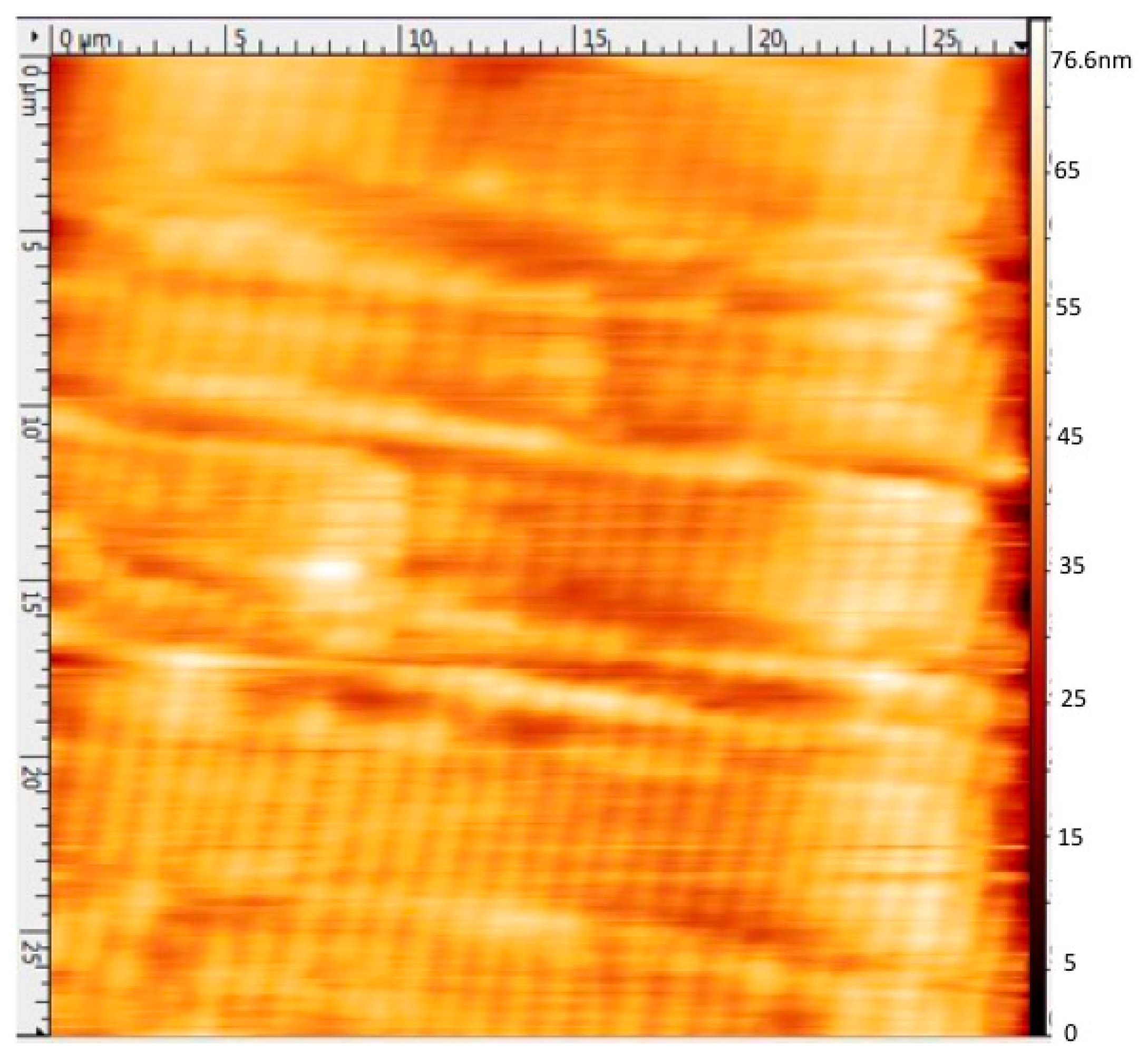
In addition, we observed a remarkable temporal robustness of the polymerized, as opposed to the unpolymerized, oily streaks. If not polymerized, oily streaks tend to destabilize within two to three weeks. However, we observed polymerized oily streaks that remained stable for well over one year, as determined by optical and atomic force microscopy (AFM). Figure 6 shows an AFM image of a 7 wt % polymerized thick film containing oily streaks more than one year after its preparation. The oily streaks’ appearance remained unchanged and the AFM image statistically is nearly identical to that obtained in previous publications, displaying the undulating topography of flattened hemicylinders [24]. Moreover, we could obtain reliable AFM images not only with the stiff stylii usually used for imaging 8CB oily streaks (stylii having a large resonant frequency of 500 kHz), but also with AFM stylii (300 kHz) that are unsuitable for non-rigid pure 8CB oily streaks, in relation to an increased rigidity with polymerization.
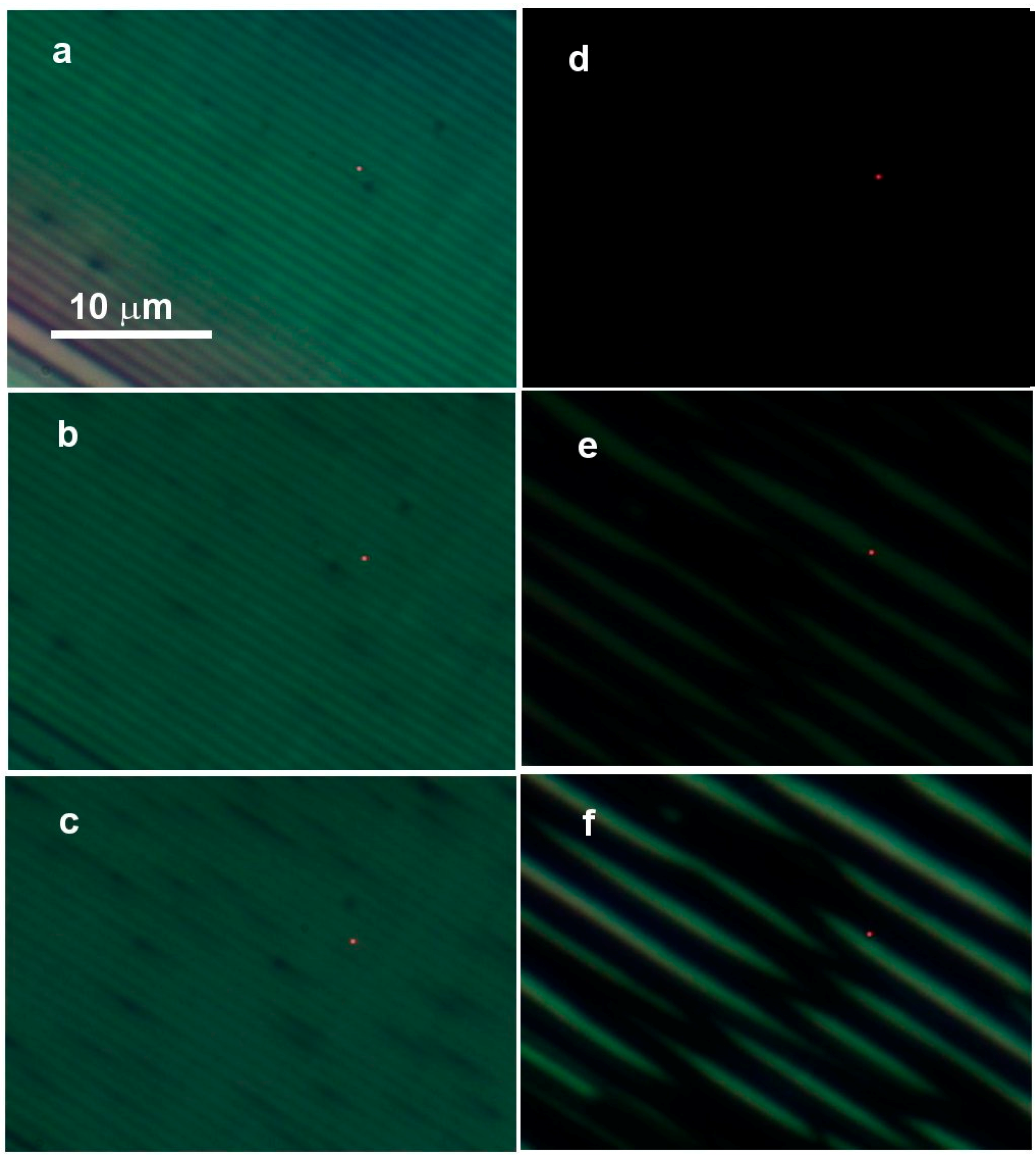
To examine the effects of film thickness, we examined a thin film of thickness from h = 450 nm while maintaining the monomer concentration at 10 wt %. At room temperature, in the Sm-A phase, well-defined oily streaks are present but with a different color due to the reduced thickness (Figure 7a). As is the case of the thick film, the oily streaks always remain intact after UV irradiation above the nematic—Sm-A transition, as seen in Figure 7b. Figure 7c shows the oily streaks, less well-defined—but still clearly discernable—at 37 °C. Figure 7d shows the film in the isotropic phase, at 42 °C. The film appears dark under crossed polarizers, corresponding to the isotropic state of the liquid crystal. After heating the liquid crystal to 70 °C and then cooling, the oily streak texture reappears on reentering the nematic phase (this is in contrast to the thick film). Figure 7e shows the thin film cooled from 70 °C to room temperature into the smectic phase. Figure 7f shows the oily streak texture after re-cooling to room temperature after heating to only 45 °C, just above the nematic—isotropic temperature; the structure is very similar to that observed after heating to 70 °C.
Additionally, we obtained SEM images of three polymerized thin films: not heated, heated to 45 °C, and heated to 70 °C. All images were obtained following the removal of the liquid crystal (after re-cooling at room temperature) by dipping the sample several times in toluene. This procedure facilitated the removal of the liquid crystal but conserved the polymer film on the surface. A polarized optical microscopy image (Figure 8) shows a polymer film without the liquid crystal. The polymer skeleton of the oily streaks shows the same periodicity as that of the liquid crystal oily streaks. Polarizing optical microscope images also show some colored areas that we attribute to remnant (unremoved) liquid crystal. Figure 9a–c show SEM images of the three samples. The oily streak-type structure of the polymer backbone is well defined, with the same periodicity as the liquid crystal oily streaks. On the other hand, and unlike the unheated sample, both heated samples show the presence of small damaged areas that appear white in the SEM images, which are more prevalent for the sample heated to 70 °C. The fact that these areas are relatively scarce after heating to 45 °C suggests that they are independent of the nematic—isotropic transition temperature. This phenomenon can thus be attributed to damage of the polymer backbone occurring at high temperature. It is interesting that such damage to the skeleton does not significantly affect the liquid crystal oily streaks remaining intact around the polymer backbone, as shown by Figure 7e,f.
3. Discussion
The results indicate that the reactive mesogen has several effects on the liquid crystal. At low concentrations, certainly up through at least 3 wt %, the reactive mesogen has no apparent effect on the oily streak structure in the Sm-A phase. This applies to both the polymerized and unpolymerized films. This behavior may be understood by the too-small-concentration of reactive mesogen, which does not allow the formation of a robust 3-D polymer network [28,29]. Thus, as with the pure 8CB film, the oily streaks vanish in the nematic phase and a uniform hybrid-aligned nematic phase appears. The only apparent effect on the phase is the decrease in the nematic—Sm-A transition temperature.
At a higher concentration (7 wt %) of RM82, TNA is further depressed to approximately 25 °C, especially in the unirradiated film. This is expected. However, after UV irradiation within the Sm-A phase, the transition temperature TNA depression from that of pure 8CB is not as large, now being approximately 28.5 °C as determined by a discontinuous change in the integrity of the streaks, in which they become more ragged above TNA. On further heating above this temperature, the oily streaks remain intact. This result bears some resemblance to previous results displaying the stabilization of smectic layer instabilities by UV-polymerization [30]. We note here that the polymer backbone stabilizes not only the highly curved smectic layers, but the topography as well. This can be seen by AFM. We observed little change in oily streak appearance up to the onset of phase separation at the nematic—isotropic transition temperature TNI ~41 °C. These behaviors indicate that the reactive mesogen, having been polymerized in the Sm-A phase, forms a skeletal structure with high curvature, as shown by SEM results (Figure 9). The structure is able to persist into the nematic phase and even into the isotropic phase, depending on the concentration of reactive mesogen and the extent of polymerization. The 8CB molecules are able to intercalate in the skeleton to lead to a texture that remains very similar to that in the Sm-A phase in the absence of polymer—and it remains stable through the entire nematic phase. Our AFM studies indicate that the skeleton is sufficiently robust to maintain the oily streaks’ integrity over extended periods of time.
However, for the polymerization of thick films, the oily streak structure was not recovered on heating into the isotropic phase and re-cooling into the Sm-A phase, independent of how far above TNI the film had been heated. In other words, once the oily streak is lost, it could not be reversed on cooling. To investigate the role of the cooling rate, we cooled the samples back to room temperature using two methods: first, by gently cooling the sample with an average cooling rate of 0.2 °C min−1; and second, by abruptly cooling the sample, i.e., by turning off the heater. We observed the same result: the LC reappears in the samples, but with a modified structure of broken and split streaks. On the other hand, for thin films, the oily streaks are recovered on cooling back into the nematic and the Sm-A phases, even if the oily streak texture is lost during the heating of the film into the liquid crystal’s isotropic phase. This shows that a gradient of polymerization may already be present for polymerized films as thin as 450 nm [16,28], thus leading to the non-rigid behavior of the thick films.
These results demonstrate two behaviors. First, when insufficiently polymerized, the polymer backbone is not rigid enough and is destroyed after heating above the nematic—isotropic transition. Looking at Figure 5e,f for the 10 wt % thick film, the appearance of bright striations in an otherwise dark background—recall that the film is between crossed polarizers at some arbitrary angle with respect to the easy axis—indicates that the liquid crystal in the “black sea” is disordered on length scales somewhat smaller than optical wavelengths. This occurs everywhere, except in the proximity of the colored striations that run parallel to the former oily streaks and have a width approximately the same as an oily streak. We believe that the dark regions in Figure 5e,f, which tend to be several times wider than the original oily streaks, represent a partial or complete collapse of the skeletal structure, with only localized order and random orientations up to length scales of several tens of nanometers remaining. On the other hand, the skeleton survives and facilitates these striations along isolated individual—or at most pairs of adjacent—former oily streaks. Previous work on liquid crystalline elastomers and reactive mesogen/liquid crystal mixtures indicates that large stresses can occur on polymers after polymerization [31], and in particular may become even larger when the surrounding liquid crystal undergoes a phase transition [32,33]. A soft or pliable substrate could reduce the stress on the skeleton, maintaining its integrity across a phase transition. For a hard substrate, such as that used in our experiment, however, there is no such mechanism to help relax the stress. Crossing a phase transition may therefore result in damage to the skeletal structure, especially if the skeleton is as rarefied, as used herein. The polymer backbone thus becomes disordered and in turn induces disorder on the surrounding liquid crystal. More complete polymerization using an intense UV source obviates this problem, and the skeletal structure remains robust at elevated temperatures in the liquid crystal’s isotropic phase.
Second, once polymerized, the liquid crystal texture is strongly impacted by the polymer backbone. Without a polymer backbone, the nematic texture on a PVA substrate is uniformly planar (Figure 3b). However, with a polymer skeleton closely mimicking the highly curved smectic layers (Figure 9), the nematic texture becomes periodic and very similar to the smectic texture. On the other hand, for thick films when the polymer backbone becomes disordered, the nematic phase displays neither a uniformly planar texture nor any periodic features, but rather it shows only disorder between planar (substrate) and homeotropically (air) oriented surfaces.
4. Materials and Methods
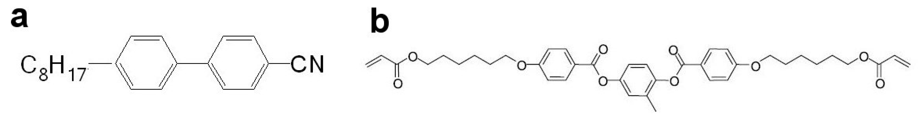
As substrates, 15 × 15 mm aluminum front surface mirrors, coated with a λ/2 film of SiO, were used in order to optimize optical contrast in reflection mode polarized microscopy measurements. The substrates were cleaned with detergent, distilled water, acetone, and ethanol. Subsequently, they were coated with polyvinyl alcohol (PVA, from Sigma-Aldrich, St. Louis, MO, USA) with an average molecular weight Mw = 85,000–124,000, baked for at least 2 h at 120 °C, and rubbed unidirectionally with a commercial rubbing cloth. This treatment results in planar alignment of the liquid crystal at the substrate. Aliquots of a 0.2 M solution of the liquid crystal octylcyanobiphenyl (8CB, Merck, Darmstadt, Germany, Figure 10a) in toluene were then doped with different concentrations—0, 3, 7, and 10 wt %—of the reactive mesogen RM82 (Synthon, Bitterfield-Wolfen, Germany Figure 10b) and 1 wt % of the photoinitiator Igracure 651 (BASF, Ludwigshafen, Germany). The monomer that we used is nematic from 86 °C to 116 °C. It presents good miscibility with the 8CB. It is indeed known that a soluble monomer usually forms networks which closely template the liquid crystalline order [12], as indeed observed in our case. A drop containing 40 μL of each of these mixtures was spin-coated (1750 rpm for 30 s) onto the planar substrate, resulting in a film of thickness of several hundred nanometers in the Sm-A phase. The rubbed PVA imposed planar alignment conditions on the liquid crystal, whereas the liquid crystal was oriented homeotropically, i.e., vertically, at the air interface. Each sample was observed under a polarizing microscope in reflection mode using a 50× objective. In well-aligned regions a series of dark and light stripes was observed, characteristic of the well-known oily streak texture [21]. From the color of the reflected light, we estimated the film thickness in the Sm-A phase based upon Newton tint tables [21,24], this measurement appearing in agreement with the relationship between thickness and period of the oily streaks previously established [27]. The samples were then irradiated in a nitrogen atmosphere with UV light of 0.15 mW cm−2 intensity at wavelength 365 nm for 20 min at a temperature T = 29.5, 23.5, and 23.5 °C for the 3, 7, and 10 wt % mixtures, which is slightly below their respective nematic—Sm-A transition temperatures (before irradiation) of 30, 24.5, and 24.5 °C, respectively (TNA = 32 °C for pure 8CB). We note that a similar lamp intensity was used for both thick and thin films. Polarizing microscope images were made as before, and AFM images were obtained using a Veeco model Nanoscope Dimension 3100 atomic force microscope and a 500 kHz cantilever/stylus in tapping mode. SEM images were obtained after the removal of the liquid crystal by dipping the film into a toluene bath and using a ZEISS scanning electron microscope.
Acknowledgments
We thank Ian R. Nemitz for useful discussions. IG, AM, and EL were supported by French state funds managed by the ANR within the Investissements d’Avenir program under Reference ANR-11-IDEX-0004-02 and more specifically within the framework of the Cluster of Excellence MATISSE. CR was supported by the National Science Foundation’s Condensed Matter Physics Program under grant DMR-1505389. IG’s travel between Paris and Cleveland was supported by a grant from the Partner University Fund.
Author Contributions
I.G., E.L., and C.R. conceived the experiment, I.G. and C.R. designed the UV apparatus, I.G. and A.M. carried out the photomicroscopy, D.D. and A.M. the SEM work, and E.L. the AFM imaging. I.G., E.L., and C.R. co-wrote the paper.
Conflicts of Interest
The authors declare no conflict of interest.
References
- Hikmet, R.A.M. From Liquid Crystalline Molecules to Anisotropic Gels. Mol. Cryst. Liq. Cryst. 1991, 198, 357–370. [Google Scholar] [CrossRef]
- Rajaram, C.V.; Hudson, S.D.; Chien, L.C. Morphology of polymer-stabilized liquid crystals. Chem. Mater. 1995, 7, 2300–2308. [Google Scholar] [CrossRef]
- Dierking, I. Polymer network–stabilized liquid crystals. Adv. Mater. 2000, 12, 167–181. [Google Scholar] [CrossRef]
- Dierking, I. Recent developments in polymer stabilised liquid crystals. Polym. Chem. 2010, 1, 1153–1159. [Google Scholar] [CrossRef]
- Evans, J.S.; Ackerman, P.J.; Broer, D.J.; van de Lagemaat, J.; Smalyukh, I.I. Optical generation, templating, and polymerization of three-dimensional arrays of liquid-crystal defects decorated by plasmonic nanoparticles. Phys. Rev. E 2013, 87, 032503. [Google Scholar] [CrossRef]
- Mirri, G.; Jampani, V.S.R.; Cordoyiannis, G.; Umek, P.; Kouwer, P.H.; Muševič, I. Stabilisation of 2D colloidal assemblies by polymerisation of liquid crystalline matrices for photonic applications. Soft Matter 2014, 10, 5797–5803. [Google Scholar] [CrossRef] [PubMed]
- Yuan, Y.; Li, Y.; Chen, C.P.; Liu, S.; Rong, N.; Li, W.; Li, X.; Zhou, P.; Lu, J.; Liu, R.; et al. Polymer-stabilized blue-phase liquid crystal grating cured with interfered visible light. Opt. Express 2015, 23, 20007–20013. [Google Scholar] [CrossRef] [PubMed]
- Park, S.; An, J.; Suk, J.W.; Ruoff, R.S. Graphene-Based Actuators. Small 2010, 6, 210–212. [Google Scholar] [CrossRef] [PubMed]
- Zhang, X.; Pint, C.L.; Lee, M.H.; Schubert, B.E.; Jamshidi, A.; Takei, K.; Ko, H.; Gillies, A.; Bardhan, R.; Urban, J.J.; et al. Optically-and thermally-responsive programmable materials based on carbon nanotube-hydrogel polymer composites. Nano Lett. 2011, 11, 3239–3244. [Google Scholar] [CrossRef] [PubMed]
- Lee, W.-E.; Jin, Y.-J.; Park, L.-S.; Kwak, G. Fluorescent actuator based on microporous conjugated polymer with intramolecular stack structure. Adv. Mater. 2012, 24, 5604–5609. [Google Scholar] [CrossRef] [PubMed]
- Kamal, T.; Park, S.-Y. A liquid crystal polymer based single layer chemo-responsive actuator. Chem. Commun. 2014, 50, 2030–2033. [Google Scholar] [CrossRef] [PubMed]
- Dierking, I.; Kosbar, L.L.; Afzali-Ardakani, A.; Lowe, A.C.; Held, G.A. Two-stage switching behavior of polymer stabilized cholesteric textures. J. Appl. Phys. 1997, 81, 3007–3014. [Google Scholar] [CrossRef]
- Mitov, M.; Boudet, A.; Sopena, P.; Sixou, P. Morphological study of a chiral polymer network in a nematic liquid crystal from a concentration gradient. Liq. Cryst. 1997, 23, 903–910. [Google Scholar] [CrossRef]
- Scharf, T. Polarized Light in Liquid Crystals and Polymers; John Wiley & Sons: Hoboken, NJ, USA, 2007. [Google Scholar]
- West, J.L. Phase separation of liquid crystals in polymers. Mol. Cryst. Liq. Cryst. Inc. Nonlinear Opt. 1988, 157, 427–441. [Google Scholar] [CrossRef]
- Agez, G.; Relaix, S.; Mitov, M. Cholesteric liquid crystal gels with a graded mechanical stress. Phys. Rev. E 2014, 89, 022513. [Google Scholar] [CrossRef] [PubMed]
- Presnyakov, V.V.; Asatryan, K.E.; Galstian, T.V.; Tork, A. Polymer-stabilized liquid crystal for tunable microlens applications. Opt. Express 2002, 10, 865–870. [Google Scholar] [CrossRef] [PubMed]
- Kikuchi, H.; Yokota, M.; Hisakado, Y.; Yang, H.; Kajiyama, T. Polymer-stabilized liquid crystal blue phases. Nat. Mater. 2002, 1, 64–68. [Google Scholar] [CrossRef] [PubMed]
- Mitov, M.; Portet, C.; Bourgerette, C.; Snoeck, E.; Verelst, M. Long-range structuring of nanoparticles by mimicry of a cholesteric liquid crystal. Nat. Mater. 2002, 1, 229. [Google Scholar] [CrossRef] [PubMed]
- Mitov, M.; Bourgerette, C.; de Guerville, F. Fingerprint patterning of solid nanoparticles embedded in a cholesteric liquid crystal. J. Phys. Condens. Matter 2004, 16, S1981. [Google Scholar] [CrossRef]
- Michel, J.-P.; Lacaze, E.; Alba, M.; De Boissieu, M.; Gailhanou, M.; Goldmann, M. Optical gratings formed in thin smectic films frustrated on a single crystalline substrate. Phys. Rev. E 2004, 70, 011709. [Google Scholar] [CrossRef] [PubMed]
- Coursault, D.; Grand, J.; Zappone, B.; Ayeb, H.; Lévi, G.; Félidj, N.; Lacaze, E. Linear Self-Assembly of Nanoparticles Within Liquid Crystal Defect Arrays. Adv. Mater. 2012, 24, 1461–1465. [Google Scholar] [CrossRef] [PubMed]
- Pelliser, L.; Manceau, M.; Lethiec, C.; Coursault, D.; Vezzoli, S.; Leménager, G.; Coolen, L.; DeVittorio, M.; Pisanello, F.; Carbone, L.; et al. Alignment of Rod-Shaped Single-Photon Emitters Driven by Line Defects in Liquid Crystals. Adv. Funct. Mater. 2015, 25, 1719–1726. [Google Scholar] [CrossRef]
- Coursault, D.; Blach, J.-F.; Grand, J.; Coati, A.; Vlad, A.; Zappone, B.; Babonneau, D.; Levi, G.; Felidj, N.; Donnio, B.; et al. Tailoring anisotropic interactions between soft nanospheres using dense arrays of smectic liquid crystal edge dislocations. ACS Nano 2015, 9, 11678–11689. [Google Scholar] [CrossRef] [PubMed]
- Gryn, I.; Lacaze, E.; Carbone, L.; Giocondo, M.; Zappone, B. Electric-Field-Controlled Alignment of Rod-Shaped Fluorescent Nanocrystals in Smectic Liquid Crystal Defect Arrays. Adv. Funct. Mater. 2016, 26, 7122–7131. [Google Scholar] [CrossRef]
- Rožič, B.; Fresnais, J.; Molinaro, C.; Calixte, J.; Umadevi, S.; Lau-Truong, S.; Felidj, N.; Kraus, T.; Charra, F.; Dupuis, V.; et al. Oriented Gold Nanorods and Gold Nanorod Chains within Smectic Liquid Crystal Topological Defects. ACS Nano 2017, 11, 6728–6738. [Google Scholar] [CrossRef] [PubMed]
- Coursault, D.; Zappone, B.; Coati, A.; Boulaoued, A.; Pelliser, L.; Limagne, D.; Boudet, N.; Ibrahim, B.H.; De Martino, A.; Alba, M.; et al. Self-organized arrays of dislocations in thin smectic liquid crystal films. Soft Matter 2016, 12, 678–688. [Google Scholar] [CrossRef] [PubMed] [Green Version]
- Relaix, S.; Bourgerette, C.; Mitov, M. Broadband reflective cholesteric liquid crystalline gels: Volume distribution of reflection properties and polymer network in relation with the geometry of the cell photopolymerization. Liq. Cryst. 2007, 34, 1009–1018. [Google Scholar] [CrossRef]
- Relaix, S.; Mitov, M. The effect of geometric and electric constraints on the performance of polymer-stabilized cholesteric liquid crystals with a double-handed circularly polarized light reflection band. J. Appl. Phys. 2008, 104, 033539. [Google Scholar] [CrossRef]
- Dierking, I.; Mitov, M.; Osipov, M.A. Smectic layer instabilities in liquid crystals. Soft Matter 2015, 11, 819–837. [Google Scholar] [CrossRef] [PubMed] [Green Version]
- Harris, K.D.; Cuypers, R.; Scheibe, P.; van Oosten, C.L.; Bastiaansen, C.W.; Lub, J.; Broer, D.J. Large amplitude light-induced motion in high elastic modulus polymer actuators. J. Mater. Chem. 2005, 15, 5043–5048. [Google Scholar] [CrossRef]
- Selinger, J.V.; Jeon, H.G.; Ratna, B.R. Isotropic-nematic transition in liquid-crystalline elastomers. Phys. Rev. Lett. 2002, 89, 225701. [Google Scholar] [CrossRef] [PubMed]
- Yuan, C.; Roach, D.J.; Dunn, C.K.; Mu, Q.; Kuang, X.; Yakacki, C.M.; Wang, T.J.; Yu, K.; Qi, H.J. 3D printed reversible shape changing soft actuators assisted by liquid crystal elastomers. Soft Matter 2017, 13, 5558–5568. [Google Scholar] [CrossRef] [PubMed]
Figure 1.
(a) Polarized reflection image of oily streaks in the smectic-A (Sm-A) phase of 8CB. Scale bar is parallel to the easy axis of the substrate’s alignment layer; (b) Schematic representation of oily streaks.
Figure 1.
(a) Polarized reflection image of oily streaks in the smectic-A (Sm-A) phase of 8CB. Scale bar is parallel to the easy axis of the substrate’s alignment layer; (b) Schematic representation of oily streaks.

Figure 2.
Crossed polarizer images of the irradiated 3 wt % thick film in the Sm-A phase at 29.5 °C (a) and in the nematic phase at 31 °C (b). In (a), light striations can be seen running from the lower left to the upper right, which are due to inhomogeneities in the substrate rubbing. Scale bar represents 10 μm.
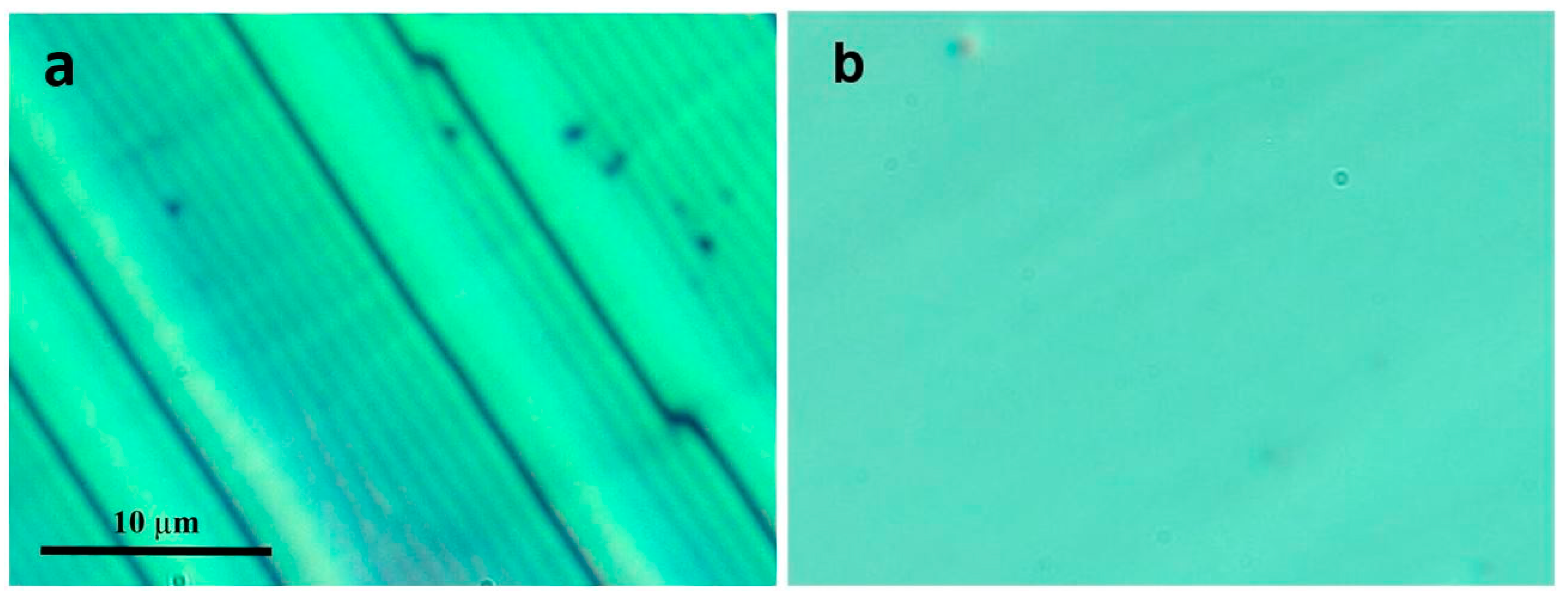
Figure 3.
Crossed polarizer images of (a) the non-irradiated 10 wt % thick film in the Sm-A phase at 22.6 °C and (b) in the nematic phase at 25 °C. Notice in (a) the oily streaks. Scale bar represents 10 μm.
Figure 3.
Crossed polarizer images of (a) the non-irradiated 10 wt % thick film in the Sm-A phase at 22.6 °C and (b) in the nematic phase at 25 °C. Notice in (a) the oily streaks. Scale bar represents 10 μm.

Figure 4.
Crossed polarizer images of the 7 wt % irradiated thick film (a) in the Sm-A phase at 27 °C; (b) just above TNA at 28.5 °C; (c) and in the nematic phase at 30 °C.
Figure 4.
Crossed polarizer images of the 7 wt % irradiated thick film (a) in the Sm-A phase at 27 °C; (b) just above TNA at 28.5 °C; (c) and in the nematic phase at 30 °C.

Figure 5.
Crossed polarizer images of the 10 wt % irradiated thick film (a) in the Sm-A phase at 23 °C; (b) in the nematic phase at 27 °C and (c) 29 °C; and (d) in the isotropic phase at 42 °C, and then on re-cooling at (e) 38 °C and (f) 23.5 °C.
Figure 5.
Crossed polarizer images of the 10 wt % irradiated thick film (a) in the Sm-A phase at 23 °C; (b) in the nematic phase at 27 °C and (c) 29 °C; and (d) in the isotropic phase at 42 °C, and then on re-cooling at (e) 38 °C and (f) 23.5 °C.

Figure 6.
Atomic force microscope picture (28 × 28 μm) of a polymerized 8CB thick film with 7 wt % of monomers. The sample was observed more than one year after its preparation, revealing a well-defined undulation of a period ~1 μm, consistent with the optical microscopy results. The topography scale is shown on the right-hand side of the image.

Figure 7.
Crossed polarizer images of the 10 wt % irradiated thin film (a) in the Sm-A phase at 23 °C; (b) in the nematic phase at 27 °C and (c) 29 °C; and (d) in the isotropic phase at 42 °C; (e) on re-cooling at 23.5 °C; after heating at 70 °C (f) and at 45 °C.
Figure 7.
Crossed polarizer images of the 10 wt % irradiated thin film (a) in the Sm-A phase at 23 °C; (b) in the nematic phase at 27 °C and (c) 29 °C; and (d) in the isotropic phase at 42 °C; (e) on re-cooling at 23.5 °C; after heating at 70 °C (f) and at 45 °C.

Figure 8.
Parallel polarizer images of the polymer thin film without the liquid crystal.
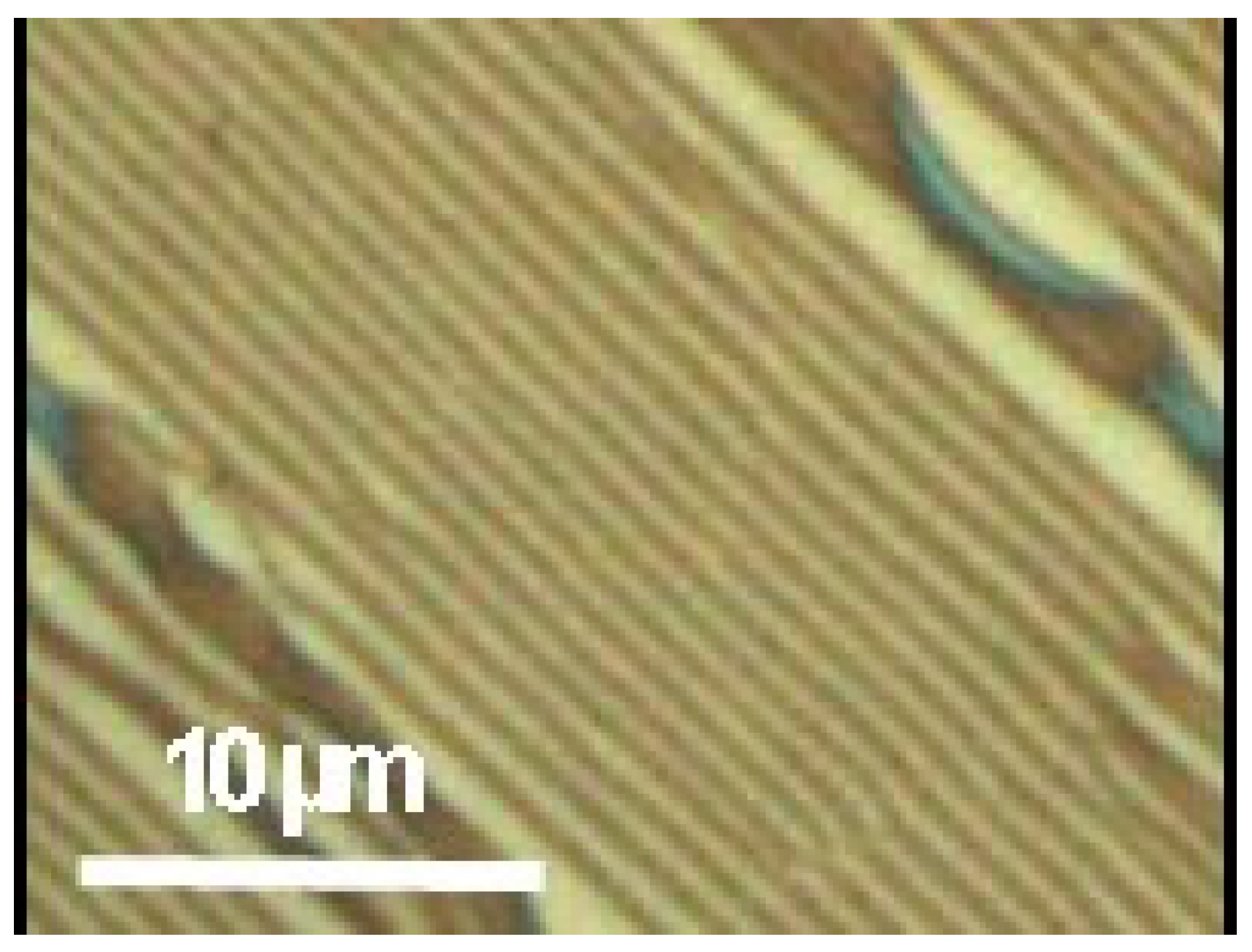
Figure 9.
SEM images of the polymer thin film without the liquid crystal (a) unheated sample; (b) sample heated at 45 °C; (c) and sample heated at 70 °C.
Figure 9.
SEM images of the polymer thin film without the liquid crystal (a) unheated sample; (b) sample heated at 45 °C; (c) and sample heated at 70 °C.

Figure 10.
(a) Liquid crystal 8CB; (b) Reactive mesogen RM82.
© 2017 by the authors. Licensee MDPI, Basel, Switzerland. This article is an open access article distributed under the terms and conditions of the Creative Commons Attribution (CC BY) license (http://creativecommons.org/licenses/by/4.0/).
Share and Cite
MDPI and ACS Style
Gharbi, I.; Missaoui, A.; Demaille, D.; Lacaze, E.; Rosenblatt, C. Persistence of Smectic-A Oily Streaks into the Nematic Phase by UV Irradiation of Reactive Mesogens. Crystals 2017, 7, 358. https://doi.org/10.3390/cryst7120358
AMA Style
Gharbi I, Missaoui A, Demaille D, Lacaze E, Rosenblatt C. Persistence of Smectic-A Oily Streaks into the Nematic Phase by UV Irradiation of Reactive Mesogens. Crystals. 2017; 7(12):358. https://doi.org/10.3390/cryst7120358
Chicago/Turabian StyleGharbi, Ines, Amine Missaoui, Dominique Demaille, Emmanuelle Lacaze, and Charles Rosenblatt. 2017. "Persistence of Smectic-A Oily Streaks into the Nematic Phase by UV Irradiation of Reactive Mesogens" Crystals 7, no. 12: 358. https://doi.org/10.3390/cryst7120358
Note that from the first issue of 2016, this journal uses article numbers instead of page numbers. See further details here.