
Influence of External Static Magnetic Fields on Properties of Metallic Functional Materials


Key Laboratory of Electromagnetic Processing of Materials (Ministry of Education), Northeastern University, Shenyang 110004, China
*
Authors to whom correspondence should be addressed.
Crystals 2017, 7(12), 374; https://doi.org/10.3390/cryst7120374
Submission received: 27 November 2017
/
Revised: 9 December 2017
/
Accepted: 11 December 2017
/
Published: 13 December 2017
(This article belongs to the Special Issue Non-Ambient Crystallography)
Abstract
:Influence of external static magnetic fields on solidification, solid phase transformation of metallic materials have been reviewed in terms of Lorentz force, convection, magnetization, orientation, diffusion, and so on. However, the influence of external static magnetic fields on properties of metallic functional materials is rarely reviewed. In this paper, the effect of static magnetic fields subjected in solidification and/or annealing on the properties of Fe–Ga magnetostrictive material, high strength high conductivity Cu-based material (Cu–Fe and Cu–Ag alloys), and Fe–Sn magnetic material were summarized. Both the positive and negative impacts from magnetic fields were found. Exploring to maximize the positive influence of magnetic fields is still a very meaningful and scientific issue in future.
1. Introduction
External static magnetic field (SMF) is one of the non-ambient thermodynamic parameters affecting thermal history during aspects of the processing of materials [1]. Lorentz force induced by the interaction between SMF and conductive melt is capable of suppressing natural convection, and thermoelectromagnetic convection can promote the convection [2]. Magnetization energy from external SMFs can change Gibbs free energy if there is a difference in magnetization energy between parent and product [3]. Thus, SMF can be introduced to modify microstructure in various materials by influencing phase equilibrium [4], phase transformation [5,6,7,8], solid solubility [9], diffusion [10], and precipitation [11,12]. There are several reviews concerning the effect of SMF on microstructure and affecting mechanisms in metallic materials [13,14,15,16,17], however, the resulting properties of metallic functional materials owing to the imposition of external SMFs are rarely reviewed. In this paper, we emphatically presented the changes in the properties of several metallic functional materials by applying external SMFs in solidification and/or annealing, and analyzed the positive trigger of SMFs.
2. Contributions of SMFs on Magnetostriction of Fe–Ga Alloy in Solidifying and Annealing
Owing to good interactive responses on reversible strains and applied magnetic fields, magnetostrictive materials are potentially used as acoustic sensors, generators, and actuators [18,19,20]. Fe–Ga alloys are firstly proposed by Clark et al. [21] as an alternative desired magnetostrictive material with high mechanical strength, large magnetostriction at low saturation fields, and high imposed stress levels, and low cost relative to the commercial Tb–DyFe2 (Terfenol-D) alloys. However, the magnetostriction of Fe–Ga alloys (about 100 ppm) is only one tenth of the magnetostrictive coefficients of Terfenol-D alloys (about 1000 ppm). High temperature disordered (A2) phase due to Ga addition is the main contribution to the increase in the magnetostriction [22]. In view of significant contributions on the magnetostriction, controlling the phase constitutions of Fe–Ga alloys is an alternative way to improve their performances. Considering that the (100) crystalline direction of the A2 phase is not only the preferred growth direction but also the easy-magnetization direction, the strongly [100] textured Fe–Ga alloys might be obtained when applying an SMF to their solidification and/or annealing. Previous investigations show that an SMF can increase the nucleation of the melts [23] and enhance the texturing degree [24,25]. Solidification under an SMF was found to increase the magnetostriction of Terfenol-D alloy because of improving texture and phases [26,27,28]. Therefore, SMF has extensive applications in the solid-solid phase transformations to alter the transformation temperatures, the phase constitutions and selection, the phase morphology and disorder-order transition [29,30]. Moreover, magnetic field annealing has been confirmed to enhance the performances of some magnetostrictive materials [31,32]. It is the purpose of the present work, to compare the effects of SMFs to magnetostriction of Fe–Ga alloys in solidifying and/or annealing processing.
With respect to the solidification of Fe–Ga alloy, the Fe–27.5wt %Ga specimens were heated and furnace cooled under Ar atmosphere to room temperature with and without a 1-T SMF. With respect to the annealing, the Fe–27.5wt %Ga specimens were heated to 1273 K at the rate of 5 K/min, held for 60 min and then furnace cooled to room temperature or quenched in water. A 12-T SMF was subjected during the annealing process. More similar experimental information could be found in our papers [33,34]. The magnetostriction of the specimens was measured using a strain gauge. In a polycrystalline material having domains initially oriented randomly, the magnetostriction can be obtained by the formula [35]:
where λtotal, λpar, λper, and λs are total magnetostriction, the magnetostriction parallel and perpendicular to longitudinal sections, and saturated magnetostriction, respectively.
λtotal = λpar − λper = 3/2λs
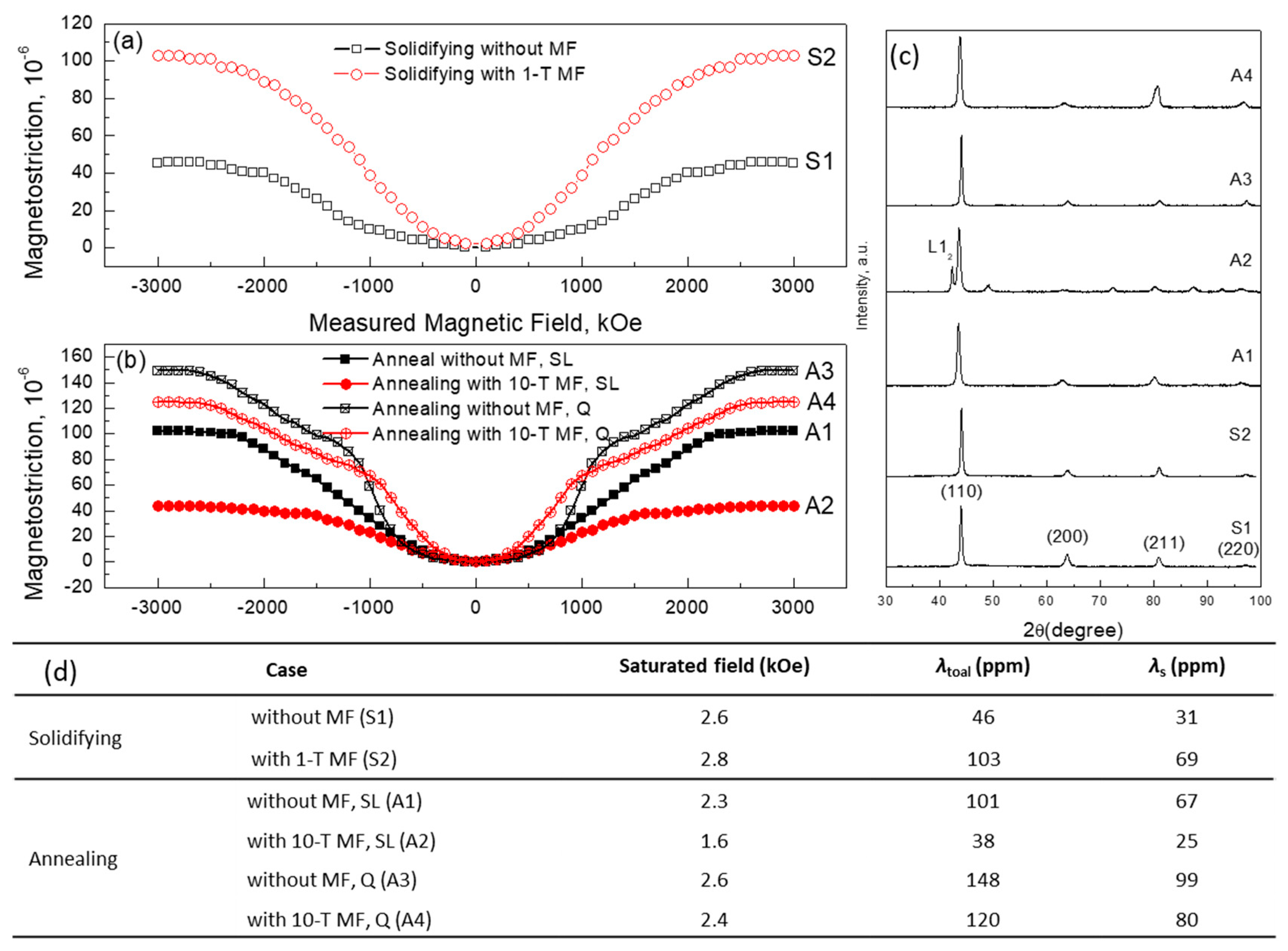
Figure 1 shows the resulting magnetostriction of Fe–27.5wt %Ga samples by applying SMFs in different processes. With increasing measured SMF, the magnetostriction of all samples increases (Figure 1a,b). When SMF is applied in the solidification process of Fe–Ga alloy (Figure 1a), the total magnetostriction of solidified Fe–27.5wt %Ga sample with an SMF is enhanced to 103 ppm from 46 ppm without an SMF (Figure 1c). That means that the saturation magnetostriction for polycrystalline Fe–27.5wt %Ga alloy solidified with 1-T SMF increases by about two times than that without an SMF. Though the magnetostrictive value of Fe–Ga alloys in our present work is not as large as the previous work from Zhou et al. [36], the imposed SMF to the solidification process of Fe–Ga alloys may be a simple but effective approach to fabricate the bulk Fe–Ga alloys. Comparing to the high saturation field of 12,000 Oe fabricated by rapid directional solidification from the undercooled melts [36], the saturation field in solidified Fe–Ga alloy with an SMF is remarkably lowered (about 3000 Oe listed in Figure 1c), which is an important factor during their applications at low fields. The improved magnetoelastic performances might to be attributed to the increasing volume fraction and texture of the disordered α-Fe phases, promoting more Ga atom clusters which was a result of the magnetic-field-undercooling and magnetic orientation induced by the applied SMF during the solidification process.
With respect to the annealing process, there are obvious decreases in the saturated magnetostriction of Fe–27.5wt %Ga alloys with a 10-T SMF compared to that without an SMF (Figure 1b (A1 and A2, or A3 and A4)). As the cooling rate increases (Figure 1b (A1 and A3, or A2 and A4)), the saturated magnetostriction of Fe–27.5wt %Ga alloys increases remarkably. The results demonstrated that applying a 10-T thermomagnetic processing to Fe–Ga alloys might increase the transformation from the disordered phases to the ordered phases, and enhance the magnetic anisotropy energy, thus decreasing the magnetostriction. Previous results from Terfenol-D alloys [37] indicated that the thermomagnetic processing introduced more additional anisotropy in the alloy with a large initial magnetocrystalline anisotropy. The increasing magnetic anisotropy energy broke the thermodynamics equilibrium of Fe–Ga system and promoted the formation of the ordered phases. Moreover, the nucleation stage rather than the growth stage during Fe–Pd ordering process induced by the external fields caused the phase transformation from the disordered A2 phases to the ordered L12 structure phases (Figure 1c confirmed it) [29]. The ordered phase products might be contributed to the decreasing magnetostriction of Fe–Ga alloys. Our result has a negative influence of high SMF on magnetostriction of Fe–27.5wt %Ga alloy, however, Wen et al. [31] found a positive influence that the saturation magnetostriction for Fe81Ga19 alloy annealed at 10 T increased by about five times compared to one without SMF. It might be resulted from the differences in composition and annealing temperature because the magnetostriction of Fe–Ga alloy is dependent on the two factors.
In summary, we applied SMFs in solidifying and annealing processes, and compared the influence of SMFs on the saturation magnetostriction. Solidifying with SMF increased the saturation magnetostriction, however, annealing with SMF decreased the magnetostriction. The changes in the saturation magnetostriction might be related to the texture, composite, thermal history. The work indicates that the imposed SMF to the solidification process of Fe–Ga alloys may be a simple but potential method to fabricate the bulk and practical Fe–Ga alloys at low fields.
3. High Strength High Conductivity Cu-Based Alloys Treated by SMFs
Conductors with high strength and high conductivity are required in construction and design of both direct current (DC) resistive and pulsed high-field magnets. Cu–Ag and Cu–Fe alloys are known to have an excellent combination of these properties. However, the increase in the strength is generally accompanied by a decrease in the electrical conductivity, and vice versa [38,39,40,41,42]. Our group applied SMFs to control the microstructures during the solidification process of the alloys in order to improve the tradeoffs between strength and electrical conductivity [43,44,45,46].
Figure 2 shows the comparison of Cu–Fe alloys by using SMFs in different processes. An external 1-T SMF was applied to the solidification process of the Cu–Fe alloy with different Fe contents [47]. The alloys solidified with and without an SMF were heavily deformed to Cu–Fe composite wires with different drawing ratios, respectively. Where, the drawing ratio is defined in term of the logarithm of the ratio of the original cross-sectional area A0 to the final area Af, functionally expressed by η = ln (A0/Af). When the drawing ratio is lower, the strength of the drawn Cu–Fe composites are lower when pre-solidified with a horizontal SMF (Figure 2a), the increase ratio in the strength of the drawn Cu–Fe composites with a 1-T SMF is quicker with increasing Fe fraction and the drawing ratio (Figure 2b). The conductivity of the drawn Cu–Fe composite wires is decreased with increasing the Fe content. The injected SMF has no effect on the electrical conductivity (EC) of the drawn wires (Figure 2b). With respect to the annealing process, with increasing annealing temperature, the ultimate tensile strength (UTS) of Cu-15wt %Fe composite increase no matter with or without SMFs (Figure 2c). Inverted “C” type tendency is found in the relationship between UTS and EC (Figure 2d) [48], which shows that the range from 450 °C to 500 °C is optimal annealing temperature for property optimization of Cu–Fe composites. SMF has a slight influence on the changes in UTS and EC.
Cu–6wt %Ag alloy was solidified with a 1.12-T SMF, and then cold rolled into Cu–Ag composites. The reduction ratio is defined as RA% = (t0 − tf)/t0 × 100, where t0 and tf are the initial and final thickness of sample, respectively. Intermedia annealing at temperature of 300 °C was applied to improve the properties of Cu–Ag composites. Cu–6wt %Ag composite with SMF had a lower hardness at a lower reduction, but had a higher hardness at a higher reduction than that without an SMF (Figure 3). We believed that more dissolved Ag in proeutectic Cu under an SMF was precipitated during rolling at a higher reduction, thus enhancing the precipitation hardening. Ageing at 300 °C promoted Ag precipitating from proeutectic Cu matrix and enhanced both microhardness and EC of Cu–6%Ag composite. More details can referred to a previous publication [44].
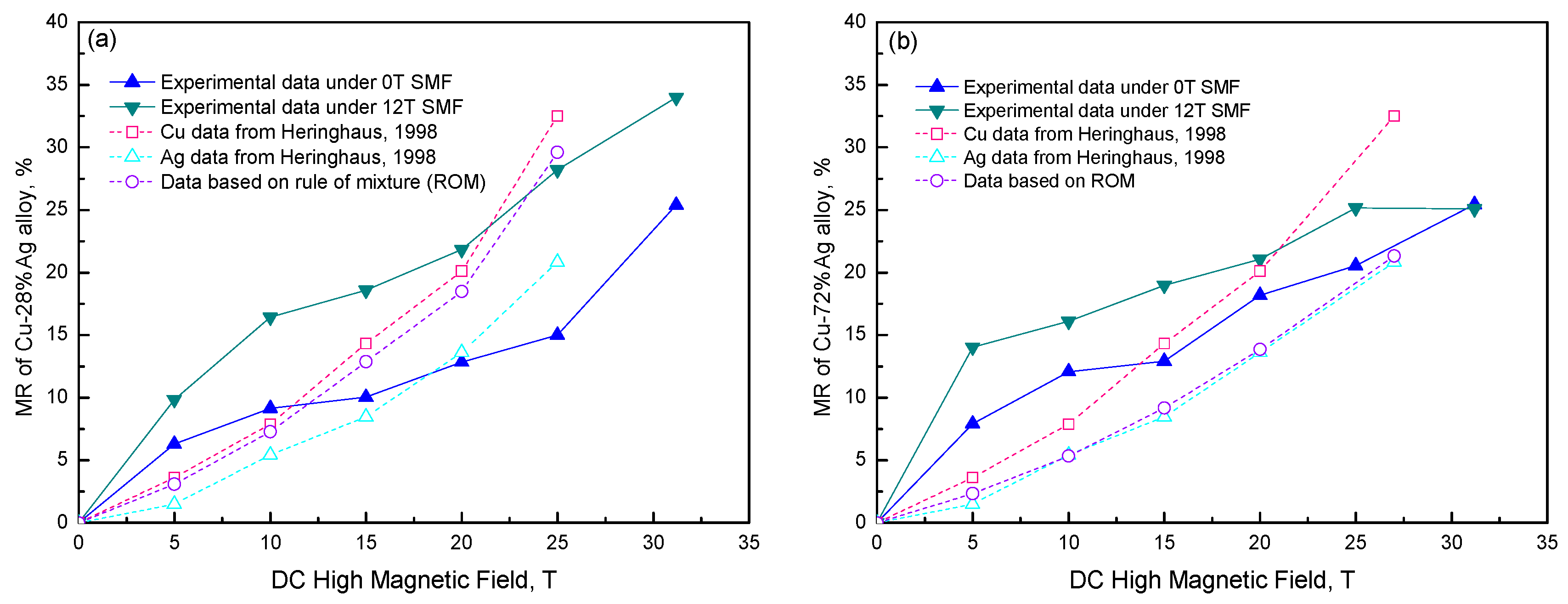
MR is generally described by [R(H, T) − R(0, T)]/R(0, T) = ΔR/R0, where R is the resistance; H and T are the magnetic field strength and temperature, respectively; R0 is the resistance at zero magnetic field. Both Cu–28wt %Ag alloy and Cu–72wt %Ag eutectic alloy were solidified with a 12-T SMF. The magnetoresistance was measured by a standard four-probe method under high magnetic fields up to 31.2 T at National High Magnetic Field Laboratory, USA. MRs of both Cu–72wt %Ag eutectic alloy and Cu–28wt %Ag alloy at 77 K are plotted as a function of the applied DC SMF in Figure 4. MR of both Cu72wt %Ag eutectic alloy and Cu–28wt %Ag alloy was increased with ramping DC SMF in the MR measurement. MR of both Cu–28wt %Ag and Cu–72wt %Ag eutectic alloys solidified under SMF were higher than that solidified without SMF. With respect to Cu–28wt %Ag alloy, the maximum MR value of Cu–28wt %Ag alloy SMF with and without SMF is 25.4% and 34.0%, respectively. Previous literatures reported that the maximum MR of drawn Cu–Ag composites at 77 K was 28% at 60 T [49] and 14% at 50 T [50]. However, their MR of as-cast Cu–Ag alloy was not reported. Previous work found revealed that MR of as-cast alloy had higher MR value than that of deformed alloy [51]. Thus, MR of as-cast Cu–Ag alloy at 77 K might be larger than 28%. Our results were almost consistent with reported results. The modeling results of Cu–28wt %Ag alloy according to the rule of mixture (ROM) were presented in Figure 4a. ROM curve is between the experimental data of sample with 12 T SMF and that without SMF. This indicates that the ROM cannot be directly used to predict the MR. The maximum MR of Cu–72%Ag eutectic alloy, as shown in Figure 4b, with and without SMF and in its absence were 25.5% and 25.2%, respectively. Our experimental results are in good agreement with the results from previous literature [50]. MR of Cu–28%Ag alloy was higher than that of the Cu–72%Ag eutectic alloy, which shows that there is a large SMF response in Cu–28%Ag alloy. More details can referred to a previous publication [52].
4. Magnetic Properties of Fe–Sn Monotectic Alloys Solidified by SMFs
Monotectic alloys have attracted attentions for their unique potential applications, including bearing materials, catalysts, permanent magnets, fine particle superconductors, and so on [53]. Most efforts have focused on obtaining homogeneous microstructure from materials having different densities which are common in monotectic systems, and on obtaining steady state coupled growth conditions in hypermonotectic alloys by directional solidification, and on modeling the monotectic growth process [54]. The SMF [55,56] and other microgravity conditions [57,58] were applied to attain controlled coupled microstructures by suppressing the melt convection. But these investigations are focused on fundamental research. Few developments are made in the applications of monotectic alloy.
Fe–49wt %Sn (mass fraction) alloys used in this work were solidified with and without SMF [33,59]. The magnetic anisotropy energies of the specimens, which are subjected to the applied magnetic fields, were estimated from the magnetization curves in the parallel direction and the perpendicular direction according to the equation:
where Eani is the magnetic anisotropy energy. M∥ and M⊥ are the magnetization of the parallel and the perpendicular to the sample axis. H is the magnetic field strength used in measuring property.
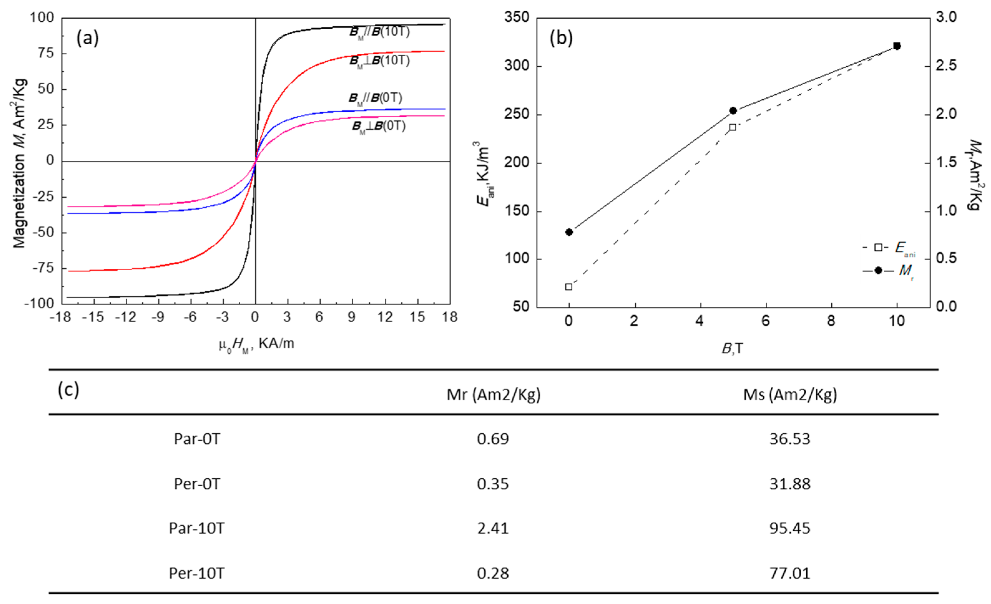
The magnetic property of the as-solidified samples (Figure 5) shows the anisotropy induced by SMF increases with increasing of the applied magnetic flux density during solidification process. Magnetic anisotropy in a system consisted of single domain (SD) magnetic grains is a factor which makes the coercivity Hc, and the remanent magnetization Mr increase. According to the experimental results, it is apparent that imposition of SMF leads to enhancement of Ms, therefore Mr is increased.
5. Conclusions and Outlook
The changes in the properties of several metallic functional materials by applying external SMFs in solidification and annealing were summarized.
(1) External SMF in solidification of Fe–27.5wt %Ga alloy increased the saturated magnetostriction, which was resulted from the induced magnetic-field-undercooling and magnetic orientation by the application of SMFs in solidification. However, SMFs in annealing decreased the saturated magnetostriction compared to those without an SMF, which was attributed to the disorder-order phase transformation induced by the application of SMFs in annealing.
(2) External SMF in solidification of Cu–Fe with over than 12% and above the drawing ratio of 3.8 will increase the UTS of Cu–Fe composite. The injected SMF has no effect on the electrical conductivity and UTS no matter which annealing temperate and SMF.
(3) Cu–6wt %Ag composite solidified with SMF and ageing at 300 °C enhanced both microhardness and electrical conductivity. MR of both Cu–28wt %Ag and Cu–72wt %Ag eutectic alloys solidified under SMF were higher than that solidified without SMF.
(4) The imposition of SMF in solidification of Fe–49wt %Sn alloy enhanced remanent magnetization and saturated magnetization, which is related to the magnetic anisotropy energies.
An SMF subjected in solidification can affect the fluid flow of the melt to modify grain orientation (Fe–Ga in this work) [60,61], primary phases (proeutectic Cu in Cu–Ag alloy, and primary Fe dendrites in Cu–Fe alloy and Fe-Sn alloy) [62,63,64]. A large fraction of grains and primary phases generally played important roles in the properties of functional metallic materials. However, when an SMF was imposed in the annealing, the magnetic energy was generally smaller than the thermal energy at room temperature or activation energy in the non-ferromagnetic systems. It was not enough to change chemical equilibrium [3], which might be one of the reasons that the properties of the four functional metallic materials were incapable of changing obviously by external SMFs. Therefore, exploring to maximize the positive influence of magnetic fields is still a very meaningful and scientific issue in future.
Acknowledgments
This work was supported by the National Natural Science Foundation of China (Nos. 51474066 and 51004038), the National Level Key Fund for Focus Research and Development Project about Intergovernmental Cooperation for Scientific Innovation (No. 2017YFE0107900), the Fundamental Research Funds for the Central Universities (No. N090309002), and the 111 Project of China (No. B07015).
Author Contributions
Xiaowei Zuo and Lin Zhang conceived and designed the experiments; Xiaowei Zuo performed the experiments; Xiaowei Zuo and Engang Wang analyzed the data; Engang Wang and Xiaowei Zuo supervised the project; Xiaowei Zuo wrote the paper. All of authors reviewed the manuscript.
Conflicts of Interest
The authors declare no conflict of interest.
References
- Enomoto, M. Enhanced phenomena in metals with electric and magnetic fields: II Magnetic fields. Mater. Trans. 2005, 46, 1088–1092. [Google Scholar] [CrossRef]
- Li, X.; Fautrelle, Y.; Gagnoud, A.; Du, D.; Wang, J.; Ren, Z.; Nguyen-Thi, H.; Mangelinck-Noel, N. Effect of a weak transverse magnetic field on solidification structure during directional solidification. Acta Mater. 2014, 64, 367–381. [Google Scholar] [CrossRef]
- Yamaguchi, M.; Tanimoto, Y. Magneto science: Magnetic field effects on materials, fundamentals and applications. In Magneto-Science; Yamaguchi, M., Tanimoto, Y., Eds.; Springer: Berlin/Heidelberg, Germany, 2006; Volume 89, pp. 1–40. [Google Scholar]
- Zhang, Y.D.; Esling, C.; Calcagnotto, M.; Gong, M.L.; Zhao, X.; Zuo, L. Shift of the eutectoid point in the Fe-C binary system by a high magnetic field. J. Phys. D Appl. Phys. 2007, 40, 6501–6506. [Google Scholar] [CrossRef]
- Liu, J.; Scheerbaum, N.; Hinz, D.; Gutfleisch, O. Martensitic transformation and magnetic properties in Ni-Fe-Ga-Co magnetic shape memory alloys. Acta Mater. 2008, 56, 3177–3186. [Google Scholar] [CrossRef]
- Kindo, K.; Hazumi, K.; Kakeshita, T.; Shimizu, K.; Hori, H.; Date, M. High magnetic field effect in martensitic transformation. Phys. B Condens. Matter 1989, 155, 207–210. [Google Scholar] [CrossRef]
- Zhang, Y.D.; He, C.S.; Zhao, X.; Zuo, L.; Esling, C. Thermodynamic and kinetic characteristics of the austenite-to-ferrite transformation under high magnetic field in medium carbon steel. J. Magn. Magn. Mater. 2005, 294, 267–272. [Google Scholar] [CrossRef]
- Han, K.; Zhou, X. Effect of high magnetic field on the processing of pearlitic steels. Mater. Manuf. Process. 2017, 32, 1–8. [Google Scholar] [CrossRef]
- Kanno, C.; Fujii, T.; Ohtsuka, H.; Onaka, S.; Kato, M. Effects of magnetic field on solid solubility of Fe and Co in a Cu matrix. In Proceedings of the 6th International Conference of Electromagnetic Processing of Materials, Dresden, Germany, 19–23 October 2009; pp. 777–779. [Google Scholar]
- Youdelis, W.V.; Colton, D.R.; Cahoon, J. On the theory of diffusion in a magnetic field. Can. J. Phys. 1964, 42, 2217–2237. [Google Scholar] [CrossRef]
- Hou, T.P.; Li, Y.; Zhang, Y.D.; Wu, K.M. Magnetic field-induced precipitation behaviors of alloy carbides M2C, M3C, and M6C in a molybdenum-containing steel. Metall. Mater. Trans. A Phys. Metall. Mater. Sci. 2014, 45, 2553–2561. [Google Scholar] [CrossRef]
- Zhou, Z.N.; Wu, K.M. Molybdenum carbide precipitation in an Fe-C-Mo alloy under a high magnetic field. Scr. Mater. 2009, 61, 670–673. [Google Scholar] [CrossRef]
- Sun, Z.H.I.; Guo, M.; Vleugels, J.; Van der Biest, O.; Blanpain, B. Strong static magnetic field processing of metallic materials: A review. Curr. Opin. Solid State Mater. Sci. 2013, 16, 254–267. [Google Scholar] [CrossRef]
- Wang, Q.; Liu, T.; Wang, K.; Gao, P.; Liu, Y.; He, J. Progress on high magnetic field-controlled transport phenomena and their effects on solidification microstructure. ISIJ Int. 2014, 54, 516–525. [Google Scholar] [CrossRef]
- Xu, Y.; Su, Y.; Luo, L.; Liu, J.; Chen, H.; Guo, J.; Fu, H. Application research status of magnetic field in materials solidification. Rare Met. Mater. Eng. 2012, 41, 548–553. [Google Scholar]
- Fautrelle, Y.; Ernst, R.; Moreau, R. Magnetohydrodynamics applied to materials processing. Int. J. Mater. Res. 2009, 100, 1389–1398. [Google Scholar] [CrossRef]
- Ma, Y.; Xiao, L.; Yan, L. Application of high magnetic fields in advanced materials processing. Chin. Sci. Bull. 2006, 51, 2944–2950. [Google Scholar] [CrossRef]
- Koon, N.C.; Williams, C.M.; Das, B.N. Giant magnetostriction materials. J. Magn. Magn. Mater. 1991, 100, 173–185. [Google Scholar] [CrossRef]
- Dubov, L.Y.; Shtotsky, Y.V.; Akmalova, Y.A.; Funtikov, Y.V.; Palacheva, V.V.; Bazlov, A.I.; Golovin, I.S. Ordering processes in Fe-Ga alloys studied by positron annihilation lifetime spectroscopy. Mater. Lett. 2016, 171, 46–49. [Google Scholar] [CrossRef]
- Balagurov, A.M.; Bobrikov, I.A.; Golovin, I.S.; Cheverikin, V.V.; Golovin, S.A. Stabilization of bcc-born phases in Fe-27Ga by adding in situ neutron diffraction study. Mater. Lett. 2016, 181, 67–70. [Google Scholar] [CrossRef]
- Clark, A.E.; Restorff, J.B.; Wun-Fogle, M.; Lograsso, T.A.; Schlagel, D.L. Magnetostrictive properties of body-centered cubic Fe-Ga and Fe-Ga-Al alloys. IEEE Trans. Magn. 2000, 36, 3238–3240. [Google Scholar] [CrossRef]
- Basumatary, H.; Palit, M.; Chelvane, J.A.; Pandian, S. Disorder trapping in gas quenched magnetostrictive Fe-Ga alloys. Mater. Sci. Eng. B Adv. 2010, 167, 210–213. [Google Scholar] [CrossRef]
- Liu, T.; Wang, Q.; Liu, F.; Li, G.J.; He, J.C. Nucleation behavior of bulk Ni-Cu alloy and pure Sb in high magnetic fields. J. Cryst. Growth 2011, 321, 167–170. [Google Scholar] [CrossRef]
- Li, X.; Fautrelle, Y.; Ren, Z.M. High-magnetic-field-induced solidification of diamagnetic Bi. Scr. Mater. 2008, 59, 407–410. [Google Scholar] [CrossRef]
- Tournier, R.F.; Beaugnon, E. Texturing by cooling a metallic melt in a magnetic field. Sci. Technol. Adv. Mater. 2009, 10, 014501. [Google Scholar] [CrossRef] [PubMed]
- Gao, P.F.; Liu, T.; Dong, M.; Yuan, Y.; Wang, Q. Magnetic domain structure, crystal orientation, and magnetostriction of Tb0.27Dy0.73Fe1.95 solidified in various high magnetic fields. J. Magn. Magn. Mater. 2016, 401, 755–759. [Google Scholar] [CrossRef]
- Wang, K.; Liu, T.; Gao, P.F.; Wang, Q.; Liu, Y.; He, J.C. Magnetostriction increase of Tb0.27Dy0.73Fe1.95 alloy prepared by solidification in high magnetic fields. Chin. Phys. Lett. 2015, 32, 4. [Google Scholar]
- Liu, T.; Liu, Y.; Wang, Q.; Iwai, K.; Gao, P.F.; He, J.C. Microstructural, magnetic and magnetostrictive properties of Tb0.27Dy0.73Fe1.95 prepared by solidification in a high magnetic field. J. Phys. D Appl. Phys. 2013, 46, 5. [Google Scholar] [CrossRef]
- Tanaka, K.; Ichitsubo, T.; Koiwa, M. Effect of external fields on ordering of FePd. Mater. Sci. Eng. A Struct. Mater. Prop. Microstruct. Process. 2001, 312, 118–127. [Google Scholar] [CrossRef]
- Kakeshita, T.; Fukuda, T. Magnetic field-control of microstructure and function of materials exhibiting solid-solid phase transformation. Sci. Technol. Adv. Mater. 2006, 7, 350–355. [Google Scholar] [CrossRef]
- Wen, S.; Ma, Y.; Wang, D.; Xu, Z.; Awaji, S.; Watanabe, K. Magnetostriction enhancement by high magnetic field annealing in cast Fe81Ga19 alloy. J. Magn. Magn. Mater. 2017, 442, 128–135. [Google Scholar] [CrossRef]
- Li, X.; Bao, X.; Liu, Y.; Yu, L.; Li, J.; Gao, X. Tailoring magnetostriction with various directions for directional solidification Fe82Ga15Al3 alloy by magnetic field heat treatment. Appl. Phys. Lett. 2017, 111, 162402. [Google Scholar] [CrossRef]
- Zuo, X.W.; Wang, E.G.; Han, H.; Zhang, L.; He, J.C. Microstructure and magnetic property of Fe–49%Sn monotectic alloys solidified under a high magnetic field. Acta Metall. Sin. 2008, 44, 1219–1223. [Google Scholar]
- Wang, E.-G.; Zhang, L.; Zuo, X.-W.; He, J.-C. Morphology of the Cu-rich phase in Cu-Pb hypermonotectic alloys under an intense magnetic field. Steel Res. Int. 2007, 78, 386–390. [Google Scholar] [CrossRef]
- Bormio-Nunes, C.; Tirelli, M.A.; Turtelli, R.S.; Grossinger, R.; Muller, H.; Wiesinger, G.; Sassik, H.; Reissner, M. Volume magnetostriction and structure of copper mold-cast polycrystalline Fe-Ga alloys. J. Appl. Phys. 2005, 97, 033901. [Google Scholar] [CrossRef]
- Zhou, J.K.; Li, J.G. An approach to the bulk textured Fe81Ga19 rods with large magnetostriction. Appl. Phys. Lett. 2008, 92, 141915. [Google Scholar] [CrossRef]
- Ma, T.Y.; Zhang, C.S.; Zhang, P.; Yan, M. Effect of magnetic annealing on magnetostrictive performance of a <1 1 0> oriented crystal Tb0.3Dy0.7Fe1.95. J. Magn. Magn. Mater. 2010, 322, 1889–1893. [Google Scholar] [CrossRef]
- Sakai, Y.; Schneider-Muntau, H.J. Ultra-high strength, high conductivity Cu-Ag alloy wires. Acta Mater. 1997, 45, 1017–1023. [Google Scholar] [CrossRef]
- Benghalem, A.; Morris, D.G. Microstructure and strength of wire-drawn Cu-Ag filamentary composites. Acta Mater. 1997, 45, 397–406. [Google Scholar] [CrossRef]
- Han, K.; Embury, J.D.; Sims, J.R.; Campbell, L.J.; Schneider-Muntau, H.J.; Pantsyrnyi, V.I.; Shikov, A.; Nikulin, A.; Vorobieva, A. The fabrication, properties and microstructure of Cu-Ag and Cu-Nb composite conductors. Mater. Sci. Eng. A Struct. Mater. Prop. Microstruct. Process. 1999, 267, 99–114. [Google Scholar] [CrossRef]
- Han, K.; Vasquez, A.A.; Xin, Y.; Kalu, P.N. Microstructure and tensile properties of nanostructured Cu-25wt%Ag. Acta Mater. 2003, 51, 767–780. [Google Scholar] [CrossRef]
- Hong, S.I.; Hill, M.A. Mechanical stability and electrical conductivity of Cu-Ag filamentary microcomposites. Mater. Sci. Eng. A Struct. Mater. Prop. Microstruct. Process. 1999, 264, 151–158. [Google Scholar] [CrossRef]
- Zhao, C.C.; Zuo, X.W.; Wang, E.G.; Han, K. Strength of Cu-28 wt%Ag composite solidified under high magnetic field followed by cold drawing. Met. Mater. Int. 2017, 23, 369–377. [Google Scholar] [CrossRef]
- Zuo, X.; Guo, R.; Zhao, C.; Zhang, L.; Wang, E.; Han, K. Microstructure and properties of Cu-6wt%Ag composite thermomechanical-processed after directionally solidifying with magnetic field. J. Alloys Compd. 2016, 676, 46–53. [Google Scholar] [CrossRef]
- Zuo, X.W.; Han, K.; Zhao, C.C.; Niu, R.M.; Wang, E.G. Microstructure and properties of nanostructured Cu28 wt%Ag microcomposite deformed after solidifying under a high magnetic field. Mater. Sci. Eng. A Struct. Mater. Prop. Microstruct. Process. 2014, 619, 319–327. [Google Scholar] [CrossRef]
- Zuo, X.W.; Qu, L.; Zhao, C.C.; An, B.L.; Wang, E.G.; Niu, R.M.; Xin, Y.; Lu, J.; Han, K. Nucleation and growth of γ-Fe precipitate in Cu–2%Fe alloy aged under high magnetic field. J. Alloys Compd. 2016, 662, 355–360. [Google Scholar] [CrossRef]
- Zuo, X.; Wang, E.; Qu, L.; Jia, P.; Zhang, L.; He, J. Strength and conductivity of deformed Cu-Fe composites after solidified with a horizontal magnetic field. Mater. Sci. Forum 2010, 654–656, 1377–1380. [Google Scholar] [CrossRef]
- Qu, L.; Wang, E.; Han, K.; Zuo, X.; Zhang, L.; Jia, P.; He, J. Studies of electrical resistivity of an annealed Cu-Fe composite. J. Appl. Phys. 2013, 113, 173708. [Google Scholar] [CrossRef]
- Rickel, D.G.; Campbell, L.J. Magnetoresistance of CuAg Wire; National High Magnetic Field Laborate: Tallahassee, FL, USA, 1996. [Google Scholar]
- Freudenberger, J.; Kozlova, N.; Gaganov, A.; Schultz, L.; Witte, H.; Jones, H. Magnetoresistance up to 50 T of highly strengthened Cu-Ag conductors for pulsed high field magnets. Cryogenics 2006, 46, 724–729. [Google Scholar] [CrossRef]
- Heringhaus, F. Quantitative Analysis of the Influence of the Microstructure of Strength, Resistivity, and Magnetoresistance of Eutectic Silver-Copper; Verlag Shaker: Aachen, Germany, 1998. [Google Scholar]
- Zuo, X.; Zhao, C.; Niu, R.; Wang, E.; Han, K. Microstructural dependence of magnetoresistance in CuAg alloy solidified with high magnetic field. J. Mater. Process. Technol. 2015, 224, 208–212. [Google Scholar] [CrossRef]
- Predel, B.; Ratke, L.; Fredriksson, H. A European Perspective: Fluid Sciences and Materials Science in Space; Walter, H.U., Ed.; Springer: Berlin, Germany, 1987; pp. 517–565. [Google Scholar]
- Andrews, J.B.; Downs, D.A.; Liu, Q.Q. Monotectic growth: Unanswered questions. Mater. Sci. Forum 2006, 508, 45–50. [Google Scholar] [CrossRef]
- He, J.; Zhao, J.; Wang, X.; Zhang, Q.; Li, H.; Chen, G. Investigation of rapid directional solidification of Al-based immiscible alloys. Acta Metall. Sin. 2007, 43, 567–572. [Google Scholar]
- Yasuda, H.; Ohnaka, I.; Dhindaw, B.K.; Takezawa, N.; Tamayama, T.; Fujimoto, S.; Tsuchiyama, A.; Nakano, T.; Uesugi, K. Evolution of regular monotectic structure during unidirectional solidification under a static magnetic field. Trans. Indian Inst. Met. 2005, 58, 625–630. [Google Scholar]
- Andrews, J.B.; Hayes, L.J.; Arikawa, Y.; Odell, J.S.; Cheney, A.B. Microgravity solidification of immiscible alloys. Mater. Sci. Forum 1996, 215–216, 59–65. [Google Scholar] [CrossRef]
- Stocker, C.; Ratke, L. Monotectic composite growth with fluid flow. J. Cryst. Growth 2000, 212, 324–333. [Google Scholar] [CrossRef]
- Zuo, X.; Wang, E.; Han, H.; Zhang, L.; He, J. Magnetic properties of Fe–49%Sn monotectic alloys solidified under a high magnetic field. J. Alloys Compd. 2010, 492, 621–624. [Google Scholar] [CrossRef]
- Li, X.; Fautrelle, Y.; Gagnoud, A.; Ren, Z.; Moreau, R. EBSD study of the influence of a high magnetic field on the microstructure and orientation of the Al-Si eutectic during directional solidification. Met. Mater. Trans. A 2016, 47, 2952–2963. [Google Scholar] [CrossRef]
- Li, Z.; Li, Z.; Yang, B.; Yang, Y.; Zhang, Y.; Esling, C.; Zhao, X.; Zuo, L. Large low-field magnetocaloric effect in directionally solidified Ni55Mn18+xGa27−x (x = 0, 1, 2) alloys. J. Magn. Magn. Mater. 2018, 445, 71–76. [Google Scholar] [CrossRef]
- Lehmann, P.; Moreau, R.; Camel, D.; Bolcato, R. A simple analysis of the effect of convection on the structure of the mushy zone in the case of horizontal bridgman solidification-comparison with experimental results. J. Cryst. Growth 1998, 183, 690–704. [Google Scholar] [CrossRef]
- Li, L.; Ban, C.; Zhang, R.; Zhang, H.; Cai, M.; Zuo, Y.; Zhu, Q.; Wang, X.; Cui, J. Morphological and crystallographic characterization of primary Zinc-rich crystals in a ternary Sn-Zn-Bi alloy under a high magnetic field. Crystals 2017, 7, 204. [Google Scholar] [CrossRef]
- Liu, H.; Xuan, W.; Xie, X.; Yu, J.; Wang, J.; Ren, Z. Effect of a high magnetic field on the microstructure in directionally solidified two-phase Ni3Al alloys. Mater. Lett. 2017, 189, 131–135. [Google Scholar] [CrossRef]
Figure 1.
Total magnetostriction curves of Fe–27.5wt %Ga alloys as a function of measured SMF at room temperature. (a) The samples were solidified with and without 1-T SMF. Black hollow squares (case S1) represents the as-solidified Fe–27.5wt %Ga alloy without SMF, and red hollow circles (case S2) represents as-solidified Fe–27.5wt %Ga alloy with 1-T SMF; (b) The samples were annealed with and without 10-T SMF. Black solid squares (case A1) represents the Fe–27.5wt %Ga alloy, processed by reheated, held and then slowly cooled to room temperature without SMF (10 K/min, SLow cooling (SL)). Red solid circles (case A2) represents similar process except with 10-T SMF (with SMF, SL). Black hollow squares (case A3) represents the Fe–27.5wt %Ga alloy, processed by reheated, held and then water quenched without SMF (As Quench, AQ). Red hollow circles (case A4) represents similar process except with 10-T SMF (with SMF, AQ). (c) X-ray diffraction pattern (XRD) of Fe-27.5wt %Ga alloys, where L12 is one of ordered phases in Fe-Ga alloy. (d) The representative data of Fe–27.5wt %Ga alloys.

Figure 2.
Ultimate tensile strength (UTS) and electrical conductivity (EC) of Cu–Fe composites by subjecting SMFs on solidification (a,b) and (c,d) annealing processes. The samples were solidified with and without a-T SMF. (a) UTS as a function of drawing ratio, where the solidified Cu-12wt %Fe alloy samples were cold drawn at room temperature; (b) UTS and EC as plotted as the Fe fraction when the solidified samples were drawn to the drawing ratio of 3.8. The Cu-15wt %Fe samples were annealed with and without SMF. (c) UTS of Cu-15wt %Fe composites as a function of annealing temperatures imposed with different external SMFs, (d) UTS and EC relationship of Cu-15wt %Fe composites.
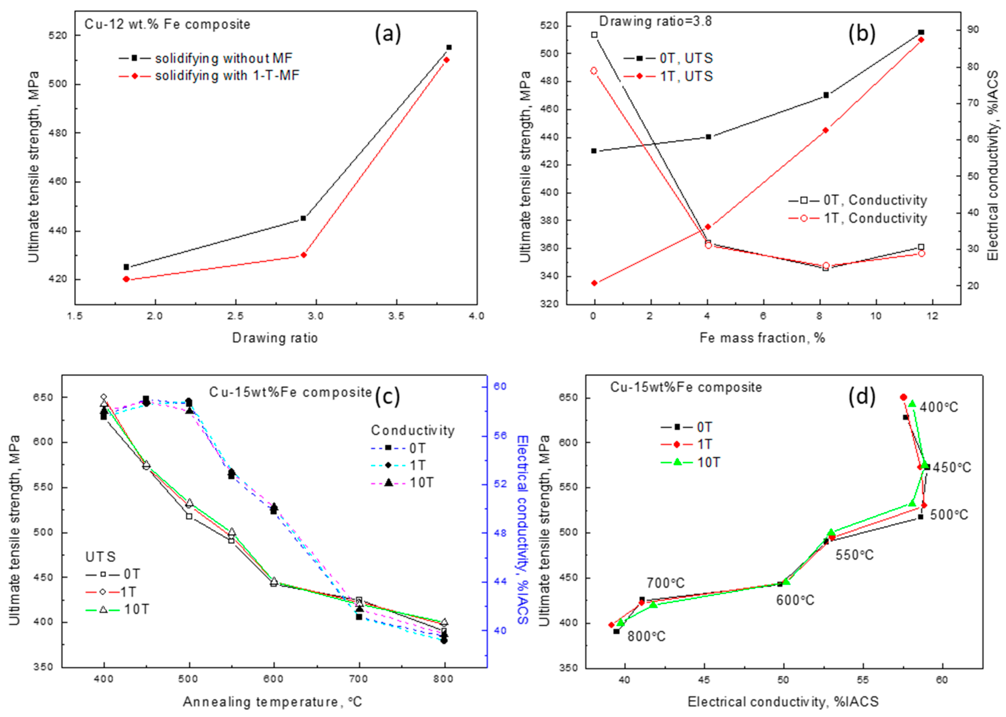
Figure 3.
(a) Microhardness and (b) Electrical resistivity of rolled Cu–6%Ag alloy with different reduction ratios after directionally solidified under SMF. The cold rolled sample with the reduction of 75% was annealed at the temperature of 300 °C. Post-annealed sample was further rolled to the reduction of 90%.
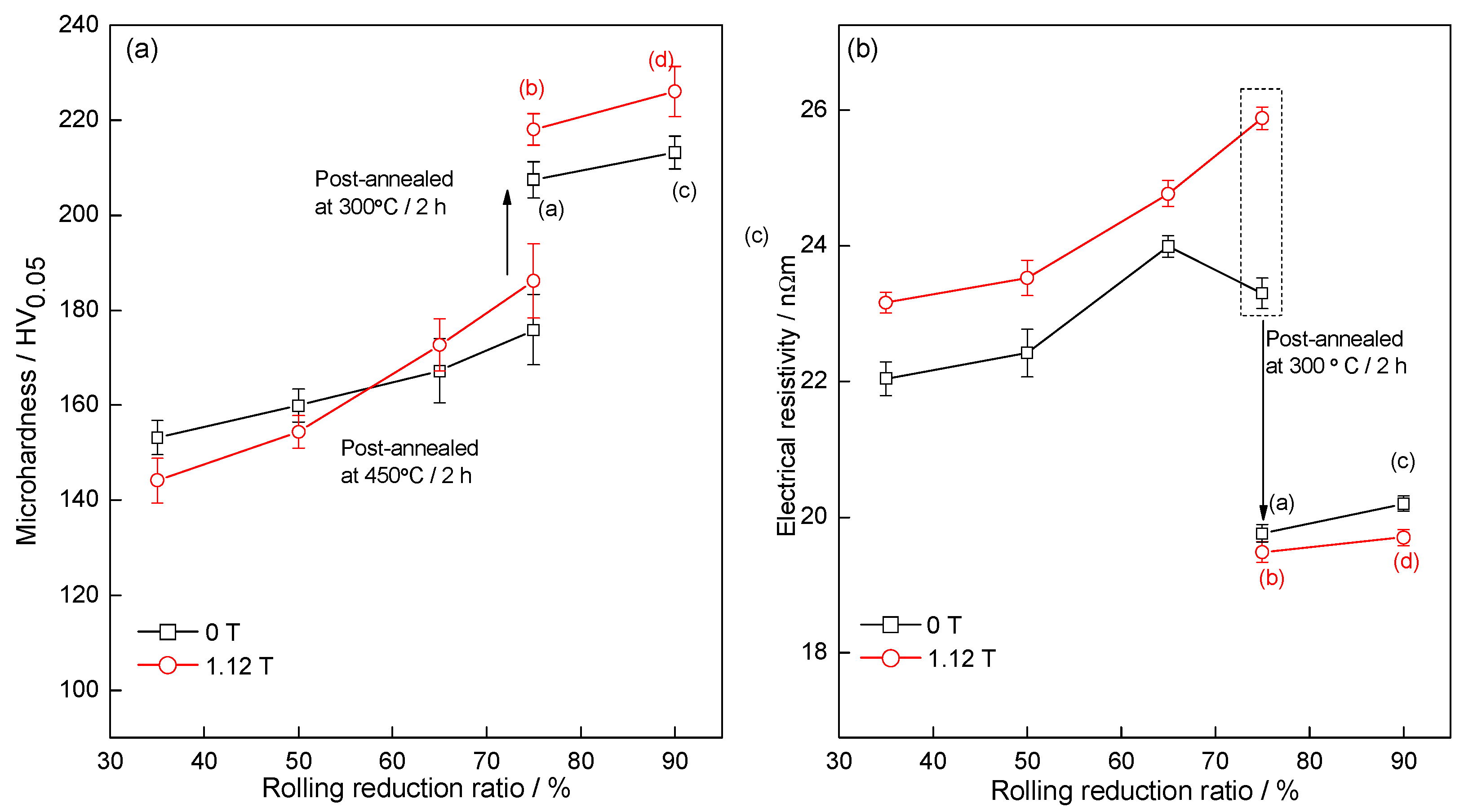
Figure 4.
MR of (a) Cu–28wt %Ag alloy, and (b) Cu–72wt %Ag eutectic alloy, at 77K as a function of the applied DC SMF, where the broken curves are the data from reference [51], and Cu–28wt %Ag and Cu–72wt %Ag ROM curve are modeled on the rule of mixture (ROM) according to MR of Cu and Ag from Reference [51].

Figure 5.
(a) Hysteresis loops of Fe–49%Sn alloys solidified under different magnetic flux densities, (b) Magnetic anisotropy energy of Fe–49%Sn alloy solidified under different magnetic flux density, and (c) the data of magnetic properties for Fe–49%Sn alloy, where “Par” and “Per” indicate “Parallel” and “Perpendicular”.

© 2017 by the authors. Licensee MDPI, Basel, Switzerland. This article is an open access article distributed under the terms and conditions of the Creative Commons Attribution (CC BY) license (http://creativecommons.org/licenses/by/4.0/).
Share and Cite
MDPI and ACS Style
Zuo, X.; Zhang, L.; Wang, E. Influence of External Static Magnetic Fields on Properties of Metallic Functional Materials. Crystals 2017, 7, 374. https://doi.org/10.3390/cryst7120374
AMA Style
Zuo X, Zhang L, Wang E. Influence of External Static Magnetic Fields on Properties of Metallic Functional Materials. Crystals. 2017; 7(12):374. https://doi.org/10.3390/cryst7120374
Chicago/Turabian StyleZuo, Xiaowei, Lin Zhang, and Engang Wang. 2017. "Influence of External Static Magnetic Fields on Properties of Metallic Functional Materials" Crystals 7, no. 12: 374. https://doi.org/10.3390/cryst7120374
Note that from the first issue of 2016, this journal uses article numbers instead of page numbers. See further details here.