
Far-field and Fresnel Liquid Crystal Geometric Phase Holograms via Direct-Write Photo-Alignment

Department of Electrical and Computer Engineering, North Carolina State University, Raleigh, NC 27695, USA
*
Author to whom correspondence should be addressed.
Crystals 2017, 7(12), 383; https://doi.org/10.3390/cryst7120383
Submission received: 1 December 2017
/
Revised: 15 December 2017
/
Accepted: 18 December 2017
/
Published: 20 December 2017
(This article belongs to the Section Liquid Crystals)
Abstract
:We study computer-generated geometric-phase holograms (GPHs) realized by photo-aligned liquid crystals, in both simulation and experiment. We demonstrate both far-field and Fresnel holograms capable of producing far-field and near-field images with preserved fidelity for all wavelengths. The GPHs are fabricated by patterning a photo-alignment layer (PAL) using a direct-write laser scanner and coating the surface with a polymerizable liquid crystal (i.e., a reactive mesogen). We study various recording pixel sizes, down to 3 μm, that are easily recorded in the PAL. We characterize the fabricated elements and find good agreement with theory and numerical simulation. Because of the wavelength independent geometric phase, the (phase) fidelity of the replay images is preserved for all wavelengths, unlike conventional dynamic phase holograms. However, governed by the diffraction equation, the size and location of a reconstructed image depends on the replay wavelength for far-field and near-field GPHs, respectively. These offer interesting opportunities for white-light holography.
1. Introduction
Liquid crystals (LCs) are one of the most widely-used materials in active and passive elements for changing a light wave’s properties. In particular, intensity, phase and polarization may all be modified by changing the LC director profile, the spatial orientation map of the optic axis. In active devices such as LC-based spatial light modulators and displays, the director profile is usually controlled by an applied voltage, which may have spatial variation depending on the application. In these cases, the surface alignment of the LC is typically simple, often uniform over relatively large areas, and the desired director profile can be realized by patterned electrodes. Conversely, geometric-phase holograms (GPHs) based on LCs [1,2,3] have an in-plane optic axis that varies spatially, often with much higher resolution than typical display pixel sizes. At least so far, GPHs are nearly always fixed orientation profiles, which may be either a passive LC polymer network film or an active LC layer whose effective retardation may be adjusted by an applied electric field. Examples of such elements are polarization gratings (PGs) [4,5], geometric-phase lenses [3], q-plates [6], beam shaping elements [7], apodizing phase plates [8] and mechanical actuators [9]. In this work, we focus both on the optical properties of these holograms and the challenges of high resolution spatial patterning in order to realize them.
2. Background
Traditional phase-only refractive and diffractive optics operate via the principle of changing the optical path length, either by modifying the refractive index or optical element thickness or both, sometimes called the dynamic phase. GPHs, however, operate via a completely different principle, the geometric phase. In LC-based GPHs, the spatially-varying in-plane optic axis orientation of the LC (i.e., the director field) is equal to one half the phase shift applied to the light wave’s phase (), sometimes called the Pancharatnam–Berry effect [10,11].
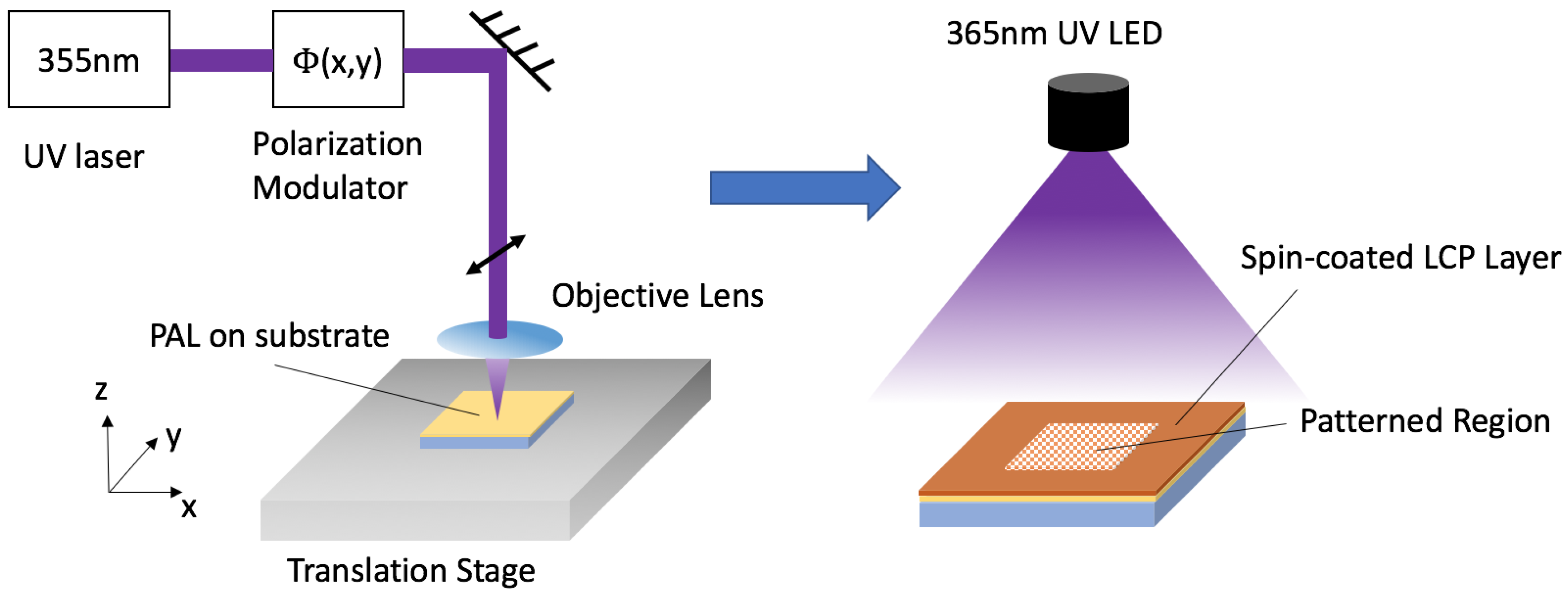
Unlike traditional surface alignment techniques such as rubbing polyimide [12], photo-alignment layers (PAL) [13,14] can fairly easily realize arbitrary, stable and high resolution surface alignment patterns. In these materials, a polymer is exposed to linearly-polarized light, usually UV, which causes isomerization [15,16], or some other molecular change, which creates a preferred alignment direction for LC that is applied subsequently. The desired orientation profiles can be realized by polarization holography [1,17,18], digital micro-mirror devices (DMDs) [19,20], plasmonic metamasks (PMMs) [21] and direct-write laser scanning [22]. While polarization holography (an interferometric method) can generate nanoscale periodic patterns [4], it cannot easily record arbitrary patterns. Notably, direct-write laser scanning stands out for the ability to record arbitrary patterns with easily adjustable pixel size, pixel number and element area. Our system currently can scan up to 200 × 200 mm2. The flexibility and precise polarization control make it ideal for recording complex patterns, such as lenses [23], q-plates, vector apodizing phase plates [8] and Fourier/Fresnel holograms [24].
Traditional computer-generated Fourier Transform holograms [25,26] are designed by retrieving the phase or amplitude profile on the hologram plane using certain algorithms [27]. This retrieved phase is traditionally assumed to arise via the dynamic phase, which is inherently wavelength dependent. Therefore, this kind of hologram can only reconstruct the image perfectly for a single wavelength, and chromatic distortion will occur for a different illumination wavelength. The geometric phase [10,11] is the phase shift acquired from changes in polarization, often conveniently considered on the Poincaré sphere. The accumulated geometric phase is path dependent and thus can be modulated by a phase retarder with an optic axis orientation profile. Because of this, the geometric phase is wavelength independent and polarization sensitive. This fundamental difference from the dynamic phase leads to very different properties of GPHs. While we employ LCs here, note that GPHs have been realized by digital holography [28] and metasurfaces (e.g., [29,30]), and a similar basic behavior has been verified.
Here, we experimentally study computer-generated GPHs via photo-aligned LCs. To obtain a complete understanding of their diffraction properties, both far-field and Fresnel holograms are demonstrated. The phase pattern of the hologram is created by an iterative phase retrieval algorithm [31] and recorded by the direct-write system [22]. We examined the wavelength and polarization dependence and the effects of different recording pixel sizes.
3. Results
3.1. Simulation Results
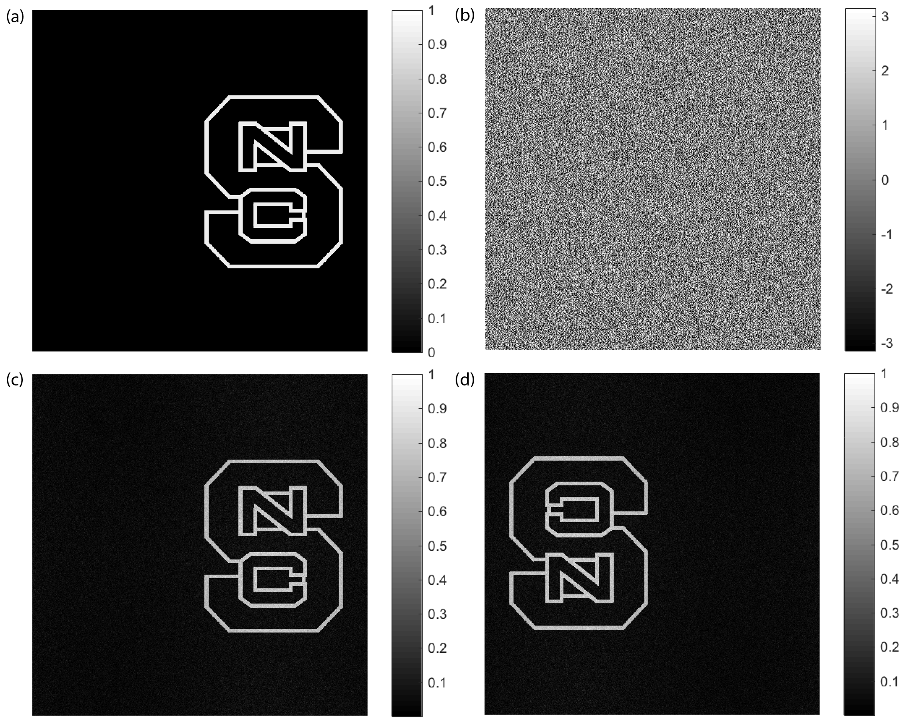
We design the hologram by phase retrieval algorithms for a 633-nm illumination wavelength and the given target image (Figure 1a), which is the logo of NC State University with 10242 pixels. The retrieved phase for the far-field hologram is shown in Figure 1b and eventually recorded by the direct-write system. Far-field and Fresnel geometric phase holograms reconstruct images at far-field and near-field, respectively, and we calculate the intensity at the image plane from the well-known diffraction equation:
where we assumed circular polarization with desired handedness to produce the primary wave [1], and stands for the Fourier transform. With the 633-nm illumination wavelength, the simulated (far-field) replay image of the primary wave is shown in Figure 1c, and the simulated conjugate image is shown in Figure 1d produced with the opposite circular polarization handedness. Note that the intensities of both simulated images are normalized, and the degraded contrast compared to the target image is caused by the error in the phase retrieval. As expected, the primary and conjugate images are inverses of one another.
Due to the polarization sensitivity, the opposite circular polarization state has the opposite sign of phase . From Equation (1) for far-field holograms, the phase with the opposite sign will only flip the replay image without distortion. However, for near-field holograms, the opposite handedness cannot preserve the fidelity of the image based on Equation (2). Note that the phases of Fresnel holograms are retrieved with certain image distance and replay wavelength .
3.2. Experimental Results
In order to achieve the best pattern quality, a test is done with various pixel sizes for the checkerboard pattern, and the result is shown in Figure 2. The checkerboard only contains zero- and 45-degree orientation angles; therefore, we expect a similar high contrast checkerboard pattern in the micrograph taken with crossed polarizers. In Figure 2a–c, the pixel size varies from 3 μm–10 μm, and we can verify sharp boundaries between neighbor pixels and high contrast in brightness, which indicates good patterning quality. In this work, all GPHs are recorded with a 5 μm pixel size to get the proper divergence of replay images for characterization.
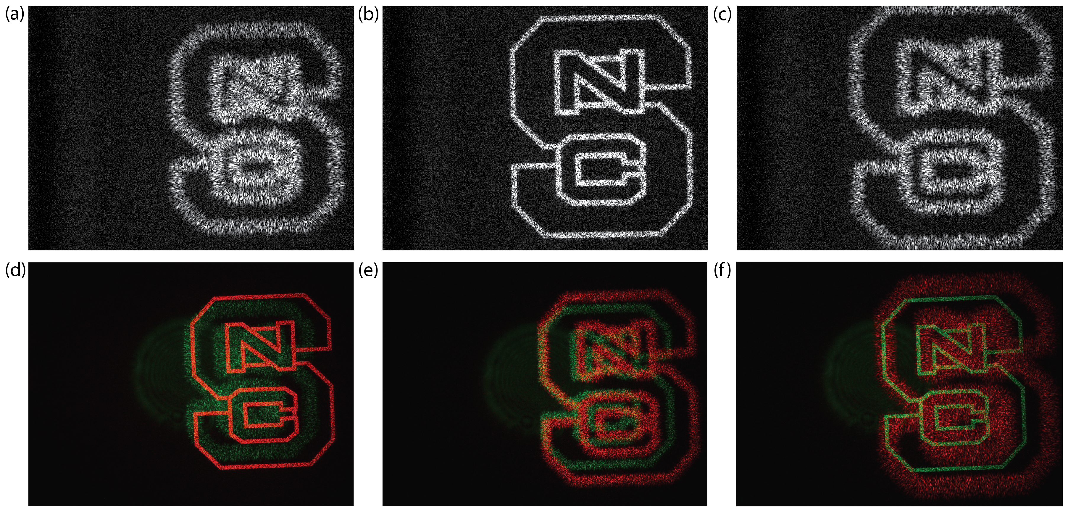
To characterize the GPHs, collimated red and green laser beams were arranged normally incident on the samples. As shown in Figure 3a for far-field holograms, images were reconstructed at the focal plane of the lens placed after the hologram. For Fresnel holograms, the replay image is directly captured a certain distance away depending on the design parameter .
For a fabricated hologram with 10242 pixels and a 5-μm pixel size, we provide the actual micrograph of the hologram captured with crossed polarizers in Figure 3b. A clear boundary between the patterned (exposed) and unpatterned (unexposed) region can be observed, and the brightness variation of the micrograph indicates the varying orientation of the optic axis as expected.
3.2.1. Far-Field Geometric Phase Hologram
For far-field GPHs, the intensity of the replay image is related to the phase profile via a simple Fourier transform. Given the focal length f of the replay lens, we rewrite the intensity at the image plane with and . Since the geometric phase is wavelength independent, for different replay wavelengths and , the replay images are related by:
where . Therefore, the reconstructed images of far-field GPHs preserve the fidelity for different wavelengths, but with a scaled size.
In Figure 4a,b, images are shown for circular polarized light input with both handedness, which verified the polarization sensitivity of GPHs. More importantly, the far-field GPH preserves the fidelity for different wavelengths as shown in Figure 4c. The scale factor of the image sizes is measured to be 0.83, which is very close to the ratio of the two wavelengths as expected. With the 633-nm illumination source, we measure about 99% of the incident power diffracted into the image.
3.2.2. Fresnel Geometric Phase Hologram
Different from the far-field GPH, the replay image of the Fresnel GPH is reconstructed at the near-field and only perfect at certain distance apart from the hologram plane for wavelength . Based on Equation (2), images of Fresnel GPH for different wavelengths will be reconstructed with the same size, but at different distances from the hologram plane. The replay distance and wavelength are related by:
The monochromatic replay images of a Fresnel GPH with cm are captured by a CCD and shown in Figure 5a–c. The quality of the replay image is best preserved near the desire value cm and degrades significantly when about deviation is present. In order to verify the wavelength dependence, colored images are taken for another Fresnel GPH with cm and shown in Figure 5d–f. As the camera is moved from cm to cm, the replay image for the red laser degrades, and the image for the green laser becomes sharper. Note that both clear images have the same size, which means the image is not scaled in the transverse direction. The best replay distance for nm is around cm, which is in good agreement with the theoretical prediction.
4. Discussion
There is no noticeable scattering observed from the film. The noise observed from the replay images is mainly caused by conventional laser speckle and perhaps, to a much lesser extent, to imperfections in the phase recording. Localized defects between neighbor pixels have no significant effects on the image quality, but may lead to higher leakage. Since the leakage at the desired wavelength is about , we conclude that alignment quality is generally good and within our expectation. Note that for both fabricated far-field and Fresnel geometric phase holograms, the zero order leakage is higher for green light since the film thickness is optimized for 633 nm. The broadband efficiency can be significantly improved when specific coating is applied, as shown in prior work [32].
The maximum pattern area for our direct-write system is limited primarily by the size of the range and acceleration of the translation stage. The total number of pixels can vary depending on the pattern and spot size. For typical discrete patterns such as a checkerboard or a hologram, we can record more than four billion pixels that can be patterned with a 3-μm pixel size. Most of the patterns we record are not pixelated at all, but instead are continuous: neighboring scans are overlapped so that the average of the exposing polarizations is recorded. In this way, we can directly scan polarization gratings with periods down to about 3 μm and achieve point defects and disclination lines between boundaries of around 1 μm in width.
With the wavelength independent geometric phase, the fidelity of replay images is preserved perfectly for different wavelengths, but a spatial offset or magnification factor nevertheless remains due to chromatic dispersion. It may be possible to realize a fully-broadband and active holographic display if both the geometric and dynamic phases are controlled simultaneously.
5. Materials and Methods
The GPHs in this work were fabricated as follows in Figure 6. We begin with coating the azo-based PAL LIA-CO01 (DIC Corp) on clean glass (D263) substrates (spin: 30 s @ 1500 rpm, bake: 60 s @ 130 °C). For exposure, we employ the direct-write laser scanner with a solid-state 355-nm laser (Coherent Inc, Santa Clara, CA, USA). The substrate is secured on an XY translation stage by vacuum and raster scanned to record the phase pattern determined from the relation at each pixel . Exposure energy is set to 1 J/cm2 to achieve adequate anchoring strength in the PAL. After exposure, the first LCP layer we coat serves the purpose of extending and enhancing the anchoring strength of the PAL to the second LCP layer. We use a first reactive mesogen solution, comprising solids RMM-A (Merck KGaA, Darmstadt, Germany, @ 633 nm) in solvent propylene-glycol-methyl-ether-acetate (PGMEA from Sigma-Aldrich, St. Louis, MO, USA), with a 5% solids concentration. This is processed (spin: 60 s @ 1000 rpm, cure: 30 s @ 190 mW of UV illumination from a 365-nm LED in dry nitrogen environment) to create a thin LCP layer, which has little contribution to the retardation. For the subsequent two layers, we use a second reactive mesogen solution with higher birefringence, comprised of 20% RMM-B (Merck KGaA, @ 633 nm) in solvent PGMEA. The processing is optimized to achieve maximum diffraction efficiency at 633 nm (spin: 60 s @ 1200 rpm, cure: 60 s @ 190 mW with a 365 nm LED in dry nitrogen environment).
6. Conclusions
In this work, we studied computer-generated GPHs realized by photo-aligned LCs. We examined the unique optical properties of both far-field and Fresnel GPHs analytically, and the corresponding simulations were performed. We recorded the holograms with a direct-write laser scanner and demonstrated good agreement with the theoretical predictions. The fabricated holograms achieved about diffraction efficiency for the desired wavelength and was verified to preserve image fidelity for all illumination wavelengths. The differences between far-field and Fresnel GPHs were observed and compared. With further study and application design, we believe that the distortion-free GPHs can provide new solutions for holographic display and sensing systems.
Acknowledgments
We thank ImagineOptix Corporation (NCSUGrant #2014-2450) for the financial support.
Author Contributions
Xiao Xiang and Michael Escuti conceived of and designed the experiments. Xiao Xiang and Jihwan Kim performed the numerical simulations and experiments and analyzed the data. Xiao Xiang and Michael Escuti wrote the paper.
Conflicts of Interest
Michael Escuti holds equity interest in ImagineOptix.
References
- Kim, J.; Li, Y.; Miskiewicz, M.N.; Oh, C.; Kudenov, M.W.; Escuti, M.J. Fabrication of ideal geometric-phase holograms with arbitrary wavefronts. Optica 2015, 11, 958–964. [Google Scholar] [CrossRef]
- De Sio, L.; Roberts, D.E.; Liao, Z.; Nersisyan, S.; Uskova, O.; Wickboldt, L.; Tabiryan, N.; Steeves, D.M.; Kimball, B.R. Digital polarization holography advancing geometrical phase optics. Opt. Express 2016, 24, 18297–18306. [Google Scholar] [CrossRef] [PubMed]
- Hasman, E.; Kleiner, V.; Biener, G.; Niv, A. Polarization dependent focusing lens by use of quantized Pancharatnam-Berry phase diffractive optics. Appl. Phys. Lett. 2003, 82, 328–330. [Google Scholar] [CrossRef]
- Xiang, X.; Kim, J.; Escuti, M.J. Nanoscale liquid crystal polymer Braggpolarization gratings. Opt. Express 2017, 25, 19298–19308. [Google Scholar] [CrossRef] [PubMed]
- Li, Y.; Kim, J.; Escuti, M.J. Orbital angular momentum generation and mode transformation with high efficiency using forked polarization gratings. Appl. Opt. 2012, 51, 8236–8245. [Google Scholar] [CrossRef] [PubMed]
- Marrucci, L.; Manzo, C.; Paparo, D. Pancharatnam-Berry phase optical elements for wavefront shaping in the visible domain: Switchable helical modes generation. Appl. Phys. Lett. 2006, 88, 221102. [Google Scholar] [CrossRef]
- Fratz, M.; Sinzinger, S.; Giel, D. Design and fabrication of polarization-holographic elements for laser beam shaping. Appl. Opt. 2009, 48, 2669–2677. [Google Scholar] [CrossRef] [PubMed]
- Snik, F.; Otten, G.; Kenworthy, M.; Miskiewicz, M.; Escuti, M.; Packham, C.; Codona, J. The vector-app: A broadband apodizing phase plate that yields complementary PSFs. Proc. SPIE 2012, 8450. [Google Scholar] [CrossRef]
- Modes, C.D.; Warner, M.; Sanchez-Somolinos, C.; de Haan, L.T.; Broer, D. Mechanical frustration and spontaneous polygonal folding in active nematic sheets. Phys. Rev. E 2012, 85, 060701. [Google Scholar] [CrossRef] [PubMed]
- Pancharatnam, S. Achromatic combinations of birefringent plates. Part 1: An Achromatic Circular Polarizer. Proc. Indian Acad. Sci. A 1955, 41, 130–136. [Google Scholar]
- Anandan, J. The geometric phase. Nature 1992, 360, 307–313. [Google Scholar] [CrossRef]
- Aerle, N.A.J.M.; Barmentlo, M.; Hollering, R.W.J. Effect of rubbing on the molecular orientation within polyimide orienting layers of liquid crystal displays. J. Appl. Phys. 1993, 74, 3111–3120. [Google Scholar] [CrossRef]
- Chigrinov, V.G.; Kozenkov, V.M.; Kwok, H.S. Photoalignment of Liquid Crystalline Materials; JohnWiley & Sons: Chichester, UK, 2008. [Google Scholar]
- Yaroshchuk, O.; Reznikov, Y. Photoalignment of liquid crystals: Basics and current trends. J. Mater. Chem. 2012, 22, 286–300. [Google Scholar] [CrossRef]
- Chigrinov, V.; Muravski, A.; Kwok, H.-S.; Takada, H.; Akiyama, H.; Takatsu, H. Anchoring properties of photoaligned azo-dye materials. Phys. Rev. E 2003, 68, 061702. [Google Scholar] [CrossRef] [PubMed]
- Shteyner, E.A.; Srivastava, A.K.; Chigrinov, V.G.; Kwok, H.-S.; Afanasyev, A.D. Submicron-scale liquid crystal photo-alignment. Soft Matter 2013, 9, 5160–5165. [Google Scholar] [CrossRef]
- Todorov, T.; Nikolova, L.; Stoyanova, K.; Tomova, N. Polarization holography. 3: Some applications of polarization holographic recording. Appl. Opt. 1985, 24, 785–788. [Google Scholar] [CrossRef] [PubMed]
- Crawford, G.; Eakin, J.; Radcliffe, M.; Callan-Jones, A.; Pelcovits, R. Liquid-crystal diffraction gratings using polarization holography alignment techniques. J. Appl. Phys. 2005, 27, 123102. [Google Scholar] [CrossRef]
- Culbreath, C.; Glazar, N.; Yokoyama, H. Note: Automated maskless micro-multidomain photoalignment. Rev. Sci. Instrum. 2011, 82, 126107. [Google Scholar] [CrossRef] [PubMed]
- Wu, H.; Hu, W.; Hu, H.; Lin, X.; Zhu, G.; Choi, J.-W.; Chigrinov, V.; Lu, Y. Arbitrary photo-patterning in liquid crystal alignments using DMD based lithography system. Opt. Express 2012, 20, 16684–16689. [Google Scholar] [CrossRef]
- Guo, Y.; Jiang, M.; Peng, C.; Sun, K.; Yaroshchuk, O.; Lavrentovich, O.; Wei, Q.-H. High-Resolution and High-Throughput Plasmonic Photopatterning of Complex Molecular Orientations in Liquid Crystals. Adv. Mater. 2016, 28, 2353–2358. [Google Scholar] [CrossRef] [PubMed]
- Miskiewicz, M.N.; Escuti, M.J. Direct-writing of complex liquid crystal patterns. Opt. Express 2014, 39, 1521–1524. [Google Scholar] [CrossRef] [PubMed]
- Hornburg, K.J.; Kim, J.; Escuti, M.J. Experimental characterization of a F/1.5 geometric-phase lens with high achromatic efficiency and low aberration. Proc. SPIE 2017, 10125. [Google Scholar] [CrossRef]
- Xiang, X.; Miskiewicz, M.N.; Escuti, M.J. Distortion-free broadband holograms: A novel class of elements utilizing the wavelength-independent geometric phase. Proc. SPIE 2015, 9386, 938609. [Google Scholar]
- Wyrowski, F.; Hauck, R.; Bryngdahl, O. Computer-generated holography: Hologram repetition and phase manipulations. J. Opt. Soc. Am. A 1987, 4, 694–698. [Google Scholar] [CrossRef]
- Yaras, F.; Kang, H.; Onural, L. Real-time phase-only color holographic video display system using LED illumination. Appl. Opt. 2005, 48, H48–H53. [Google Scholar] [CrossRef] [PubMed]
- Fienup, J.R. Phase retrieval algorithms: A comparison. Appl. Opt. 1982, 21, 2758–2769. [Google Scholar] [CrossRef] [PubMed]
- Jackin, B.J.; Narayanamurthy, C.S.; Yatagai, T. Geometric phase shifting digital holography. Opt. Lett. 2016, 41, 2648–2651. [Google Scholar] [CrossRef] [PubMed]
- Zheng, G.; Muhlenbernd, H.; Kenney, M.; Li, G.; Zentgraf, T.; Zhang, S. Metasurface holograms reaching 80% efficiency. Nat. Nanotechnol. 2015, 10, 308–312. [Google Scholar] [CrossRef] [PubMed]
- Choudhury, S.; Guler, U.; Shaltout, A.; Shalaev, V.M.; Kildishev, A.V.; Boltasseva, A. Pancharatnam-Berry Phase Manipulating Metasurface for Visible Color Hologram Based on Low Loss Silver Thin Film. Adv. Opt. Mater. 2017, 5, 1700196. [Google Scholar] [CrossRef]
- Fienup, J.R. Iterative method applied to image reconstruction and to computer-generated holograms. Appl. Opt. 1980, 19, 297–305. [Google Scholar] [CrossRef]
- Oh, C.; Escuti, M.J. Achromatic diffraction from polarization gratings with high efficiency. Opt. Lett. 2008, 33, 2287–2289. [Google Scholar] [CrossRef] [PubMed]
Figure 1.
(a) Target image; (b) retrieved phase pattern; (c) simulated replay of the primary image, from one circular polarization; (d) simulated replay of the conjugate image, from the orthogonal circular polarization.
Figure 1.
(a) Target image; (b) retrieved phase pattern; (c) simulated replay of the primary image, from one circular polarization; (d) simulated replay of the conjugate image, from the orthogonal circular polarization.

Figure 2.
Micrographs of samples with checkerboard patterning with a (a) 3-μm pixel size, (b) 5-μm pixel size and (c) 10-μm pixel size.
Figure 2.
Micrographs of samples with checkerboard patterning with a (a) 3-μm pixel size, (b) 5-μm pixel size and (c) 10-μm pixel size.
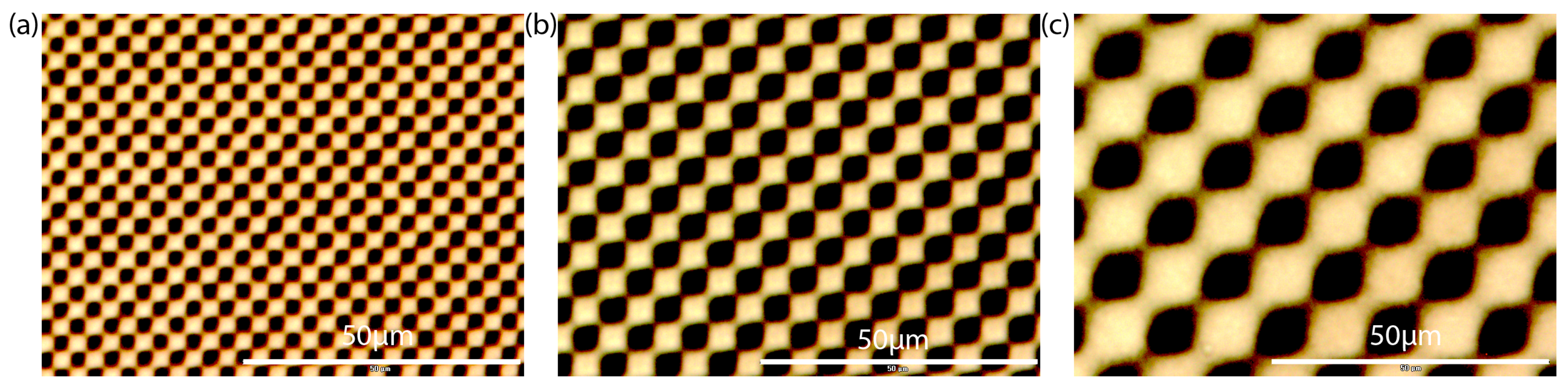
Figure 3.
(a) Illustration of the characterization setups; (b) micrograph at the edge of a far-field liquid crystal geometric-phase hologram (GPH) with a 5-μm pixel size, between crossed polarizers.
Figure 3.
(a) Illustration of the characterization setups; (b) micrograph at the edge of a far-field liquid crystal geometric-phase hologram (GPH) with a 5-μm pixel size, between crossed polarizers.
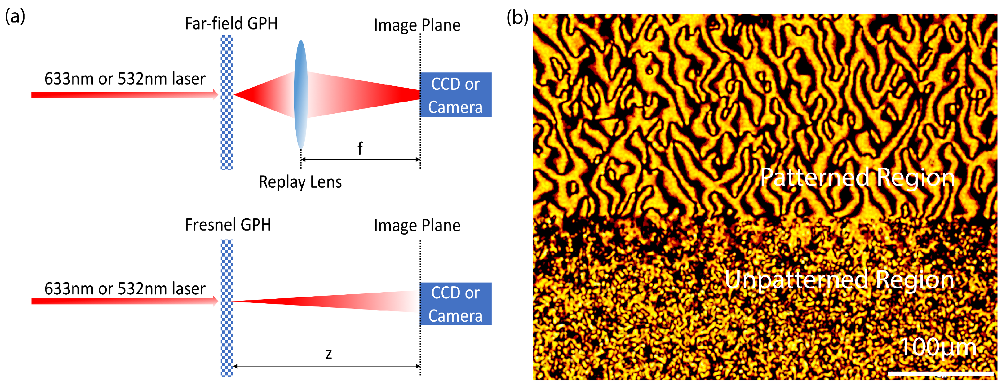
Figure 4.
Measured replay images for a (a) 633-nm laser with opposite circular polarization, (b) 633-nm laser with desired circular polarization and (c) 633-nm and 532-nm lasers with desired circular polarization.
Figure 4.
Measured replay images for a (a) 633-nm laser with opposite circular polarization, (b) 633-nm laser with desired circular polarization and (c) 633-nm and 532-nm lasers with desired circular polarization.
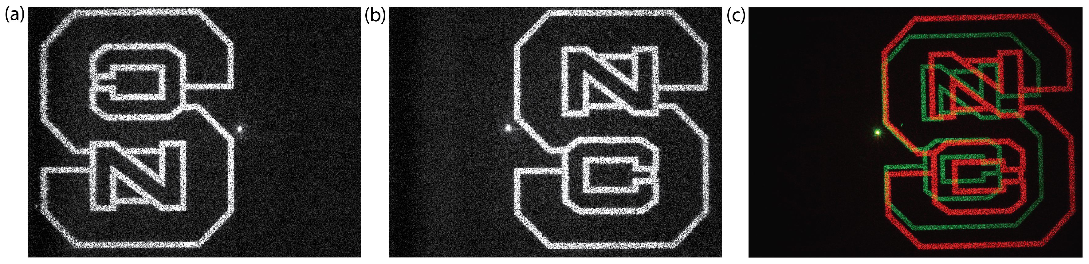
Figure 5.
Measured monochromatic replay images by a CCD for a 633-nm laser illumination with desired polarization input of (a) z = 4.5 cm, (b) z = 5 cm and (c) z = 5.5 cm. Captured colored replay images by a camera for a 633-nm and a 532-nm laser illumination with desired polarization input of (d) z = 7.5 cm, (e) z = 8.3 cm and (f) z = 8.9 cm.

Figure 6.
Illustration of the fabrication steps including UV exposure by the direct-write system and UV curing of the spin-coated LCPlayer.
Figure 6.
Illustration of the fabrication steps including UV exposure by the direct-write system and UV curing of the spin-coated LCPlayer.

© 2017 by the authors. Licensee MDPI, Basel, Switzerland. This article is an open access article distributed under the terms and conditions of the Creative Commons Attribution (CC BY) license (http://creativecommons.org/licenses/by/4.0/).
Share and Cite
MDPI and ACS Style
Xiang, X.; Kim, J.; Escuti, M.J. Far-field and Fresnel Liquid Crystal Geometric Phase Holograms via Direct-Write Photo-Alignment. Crystals 2017, 7, 383. https://doi.org/10.3390/cryst7120383
AMA Style
Xiang X, Kim J, Escuti MJ. Far-field and Fresnel Liquid Crystal Geometric Phase Holograms via Direct-Write Photo-Alignment. Crystals. 2017; 7(12):383. https://doi.org/10.3390/cryst7120383
Chicago/Turabian StyleXiang, Xiao, Jihwan Kim, and Michael J. Escuti. 2017. "Far-field and Fresnel Liquid Crystal Geometric Phase Holograms via Direct-Write Photo-Alignment" Crystals 7, no. 12: 383. https://doi.org/10.3390/cryst7120383
Note that from the first issue of 2016, this journal uses article numbers instead of page numbers. See further details here.