
Morphology of Spherulites in Rapidly Solidified Ni3Ge Droplets

School of Chemical & Process Engineering, University of Leeds, Leeds LS2 9JT, UK
*
Author to whom correspondence should be addressed.
Crystals 2017, 7(4), 100; https://doi.org/10.3390/cryst7040100
Submission received: 26 January 2017
/
Revised: 22 March 2017
/
Accepted: 29 March 2017
/
Published: 1 April 2017
(This article belongs to the Special Issue Crystal Morphology and Assembly in Spherulites)
Abstract
:The congruently melting, single phase, L12 intermetallic β-Ni3Ge has been subject to rapid solidification via drop-tube processing. Four different cooling rates are used in this process, at very low cooling rates (≥850 μm diameter particles, ≥700 K s−1) and slightly higher cooling rates (850–500 μm diameter particles, 700–1386 K s−1) the dominant solidification morphology, revealed after etching, is that of isolated spherulites in an otherwise featureless matrix. At higher cooling rates, (500–300 μm diameter particles, 1386–2790 K s−1 and (300–212 μm diameter particles, 2790–4600 K s−1) mixed spherulite and dendritic morphologies are observed. Indeed, at the higher cooling rate dendrites with side-branches composed of numerous small spherulites are observed. Selected area diffraction analysis in the TEM indicate that the formation of spherulites is due to an order-disorder transformation. Dark-field TEM imaging has confirmed that the spherulites appear to consist of lamellae of the ordered phase, with disordered material in the space between the lamellae. The lamellar width within a given spherulite is constant, but the width is a function of cooling rate, with higher cooling rates giving finer lamellae. As such, there are many parallels with spherulite growth in polymers.
1. Introduction
Intermetallic compounds are characterised by a high degree of chemical ordering and mixed covalent/ionic and metallic bonding, which gives rise to mechanical behaviour intermediate between ceramics and metals. Due to these characteristics they can display desirable magnetic, superconducting and chemical properties [1]. They also have a range of potential applications as high temperature structural materials due to good chemical stability and high hardness at elevated temperatures. Conversely, poor room temperature ductility limits formability, although this can be increased by rapid solidification processing, wherein a reduction of the degree of chemical order and the formation of a fine pattern of antiphase domains (APDs) increases ductility [2,3,4]. Moreover, the high temperature properties can be restored by chemical ordering via annealing out the APDs subsequent to forming [2].
We present here an analysis of the rapid solidification of β-Ni3Ge, a congruently melting, single phase intermetallic having a melting point of 1405 K and a homogeneity range of 22.5 to 25 at % Ge [5]. β-Ni3Ge has the L12 crystal structure, this being an ordered variant of the face centred cubic structure. This structure is adopted by many ordered systems with the stoichiometry X3Y, with X atoms sitting on the faces and Y atoms on the corners of the cubic unit cell. At equilibrium, β-Ni3Ge orders at all temperatures below the liquidus, with crystallization from the liquid resulting directly in the ordered L12 structure. Consequently, rapid solidification processing has the capacity to induce disorder trapping [6] wherein, the degree of chemical ordering will decrease with increasing solidification velocity as progressively higher levels of chemical disorder are trapped in the structure. For β-Ni3Ge this will result in the ordered L12 structure being replaced by a random solid-solution with the fcc crystal structure.
The system has previously been studied by Ahmed et al. [7] using a flux undercooling technique, wherein they attained a maximum undercooling of 362 K, with a measured growth velocity of 3.55 m s−1. They also observed a break in the velocity-undercooling curve which they attributed to the transition between growth of the ordered phase at low undercooling to growth of the fully disordered form (complete disorder trapping) at high undercooling, this condition being met at an undercooling of 168K and at a critical growth velocity, Vc of 0.22 m s−1. Such transitions have previously been reported by a number of authors see e.g., [8] and have been predicted theoretically by West and Aziz [9]. However, in the flux undercooling technique post solidification cooling rates tend to be very low (<10 K s−1), meaning that solidification microstructures tend to be subject to extensive solid-state transformation.
The aim of this investigation is to study the solidification morphologies which are associated with disorder trapping at high growth rate, using drop-tube processing. Being congruently melting, β-Ni3Ge is an ideal system for this as disorder trapping will occur without the associated complication of solute trapping. Moreover, unlike the flux undercooling technique used by Ahmed et al., drop-tube cooling rates are sufficiently high so as to supress recrystallization, solid-state phase transformations and, for the smaller droplets sizes, chemical reordering thereby giving a much higher probability that the original solidification morphology will be retained. A somewhat surprising outcome of the work, discussed in detail below, was the ubiquitous occurrence of spherulites, a morphology that, as far as we are aware, is not observed to form in any other fully crystalline, non-glass forming alloy. The aim of this paper is therefore to explore the similarities and difference between the spherulite morphologies observed here and those seen more commonly in polymer and glass forming alloy systems. However, a review of the spherulite morphology and its previous occurrence in metallic systems is presented first.
In 1837, Talbot observed a spherical crystalline morphology during the crystallization of borax from phosphoric acid [10]. Based upon their morphology, spherulites are normally characterised as being either Category 1 or Category 2. A Category 1 spherulite develops radially from the nucleation site, branching intermittently to maintain space filling. Category 2 develop initially as thread like fibres, successively forming new grains at the growth front [11,12]. Later, Brewster named the objects of Talbot’s interest ‘circular crystals’ [13], for which the term spherulite has become generally accepted. Spherulites are common in polymers and small molecule organic crystals but are also observed in some minerals, volcanic rocks, inorganic crystals and a few pure elements (e.g., graphite, sulphur and selenium) [14]. However, the development of spherulites are only rarely observed in fully crystalline metals, sometimes in cast iron (graphite), although they are observed in partially crystalline glass forming alloys, both as residual crystals following solidification and as devitrification products [14].
Typical polymer spherulites form most readily from melts with a high molecular weight, particularly under growth conditions where topological constraints inhibit the reorientation of long chain molecules. Formation is particularly favoured in situations where a random molecular orientation might be expected, such as growth from an undercooled melt. Conversely, for growth with a strong externally imposed directionality, such as in a temperature gradient, spherulite growth appears to be suppressed [15]. These spherulite structure generally have multiply branched crystalline arms which are separated by amorphous regions between the arms [14]. The amorphous regions are typically shorter than the molecular chains, such that one molecule may go through many such crystalline and amorphous regions [16].
The growth of spherulites is also observed in a number of metallic systems, particularly metallic glass forming alloys, in which they are observed both as residual crystals during freezing from the melt and amorphous-crystalline composite structures during devitrification of the fully amorphous material. Examples of such residual spherulitic crystals forming direct from the melt have been observed by Lu et al. [17] during Bridgeman solidification of La–Al–Ni glass forming alloys. For pulling speeds of 2.3–2.4 mm s−1 spherulites between 10 and 30 μm in diameter were observed, whereas at higher pulling speeds fully amorphous material was observed. These spherulites were crystalline eutectic structures in an amorphous matrix, although Lu et al. did not identify the crystalline phases comprising the eutectics.
Also during Bridgeman solidification, but in a Zr–Ti–Cu–Ni–Be glass forming alloy, Cheng et al. [18] identified a range of multiply branched crystalline morphologies embedded in an amorphous matrix. One of the phases present was identified as Zr2Cu, although other phases were also present and could not be identified by the authors. These structures, which again were favoured by low pulling speeds, had an elliptical outer envelope, but the orientation of the crystalline needles within the structures had features reminiscent of Category 2 spherulites.
Somewhat larger spherulitic crystals, up to 120 μm in diameter, were observed by Aboki et al. [19] in Zr–Cu–Al–Ni glass forming alloys cast into a water cooled copper mold with cooling rates estimated around 100 K s−1. Again these are crystalline, probably eutectic, structures embedded within an amorphous matrix. XRD analysis identified at least 9 crystalline phases present within these samples, although the authors were unable to identify which contributed to the spherulite structures.
The devitrification during annealing of Fe–Si–B soft magnetic metallic glasses has been studied by a number of authors, with various morphologies, including spherulites, being observed depending upon the composition studied. For the Fe75Si12B13 composition the spherulites were composed of the metastable intermetallic Fe3B, which decomposed to Fe2B in fully crystalline samples [19]. Conversely, for the Fe75Si9B16 composition three discrete stages of crystallisation were revealed upon heating of the sample [20], with spherulites of pure Fe being formed during the first stage.
Yano et al. [21] observed the formation of spherulites in a Zr50Cu40Al10 bulk metallic glass forming alloy via TEM and positron annihilation lifetime measurements. Upon annealing at 773 K, crystallisation proceeded through the formation of spherical agglomerates of radially developing crystallites, about 600 nm in diameter. Selected area diffraction patterns were used to identify the crystallography of both the spherulites and the surrounding matrix material. The space group for the spherulites was thought to be one of the orthorhombic groups, the inter-spherulite region displayed a two-fold symmetry and was identified as an fcc structure.
Numerous further studies [21,22,23,24] have also observed the formation of nano-crystalline spherulites during the devitrification of both binary and multicomponent component metallic glass systems. In virtually all cases the spherulites are homogenously distributed within the amorphous matrix, with a radial growth originating from the centre of nucleation sites. This would suggest that spherulite growth is initiated on pre-existing nuclei frozen into the metallic glass. The results appear to be insensitive to the heating rate, with heating rates as high as 10³ K s−1 being found not to inhibit spherulite crystallisation [25].
In a study of the crystallisation of Zr58.5Cu15.6Ni12.8Al10.3Nb2.8 bulk metallic glass in DSC (differential scanning calorimetry), Sun and Flores [26] found that high heating rates (>2.5 K s−1) resulted in the formation of spherulites. In contrast, low heating rates resulted in non-spherulite nano-crystalline structures, wherein they concluded that the activation energy required for the formation of nano-crystalline structures is higher than that required for the formation of spherulites. In a laser processing study of the same alloy [27] they further observed that spherulites can form at the same composition as the amorphous matrix, i.e., without partitioning.
Although the mechanism for spherulitic growth is the subject of some controversy, a number of common requirements have been identified. The first is a tendency towards non-crystallographic, small angle branching [28]. The second is a high viscosity in the medium being crystallized. Morse et al. [29,30] demonstrated this in a comparative study of the crystallisation of 70 salts, showing that crystallization to spherulites only occurred for growth in a gel based media. The requirement for a high viscosity in the melt would be consistent with the propensity for glass forming alloys, but not other metallic melts, to crystallise to spherulitic morphologies.
In developing a phase-field model of spherulite growth in polymers, Gránásy and co-workers found that the morphology is favoured in situations in which translational diffusion is easier than rotational diffusion [31]. However, while it is possible that this situation may emerge during the crystallization of long chain polymers it is far less clear how such a situation could emerge in metals. There is some evidence that similar conditions could be found in both organic [32] and metallic [33] undercooled glass forming liquids. These are characterized by a decoupling of the translational diffusion coefficient from the macroscopic viscosity, as well as of the translational and rotational diffusion coefficients. The inclination of metallic glass formers to form spherulites indicates that some level of structure in the non-crystalline precursor is required. This also appears to be the case for other spherulite formers. For instance, pure elemental Se is reported to have a very peculiar molecular structure that is intermediate between polymeric and simple molecular liquids [34].
In this article we present an analysis of rapidly solidified Ni-23.8 at % Ge produced using the drop-tube technique. Four very different microstructures, spherulites, orthogonal dendrites, non-orthogonal and dendritic seaweed have previously been reported in this system as the cooling rate is increased [35,36]. Given the relative rarity of spherulite formation in non-glass forming metallic melts this article focuses solely on the spherulite structures. Such spherulites are observed to form for cooling rates in the range 700–4600 K s−1, corresponding to droplets sizes of >850 μm, 850–500 μm, 500–300 μm and 300–212 μm. The objective is to understand the origin of these structures by using TEM to probe the extent of chemical ordering with in the spherulites and Electron backscatter diffraction (EBSD) to investigate the extent to which the spherulites share a common crystallography with the grains in which they are embedded.
2. Results and Discussion
Figure 1a,d shows SEM micrographs of the polished and etched sections from the four sieve size fractions >850 μm, 850–500 μm, 500–300 μm and 300–212 μm respectively. In the two largest sieve sizes (Figure 1a,b) numerous spherulite morphologies are evident, typically with diameters in the range 10–20 μm. In these droplets sizes the spherulites are the only solidification morphology observed in what is otherwise a featureless background.
In the two smaller sieve sizes various spherulite morphologies are still evident, but these are now smaller and coexist with dendrites. Figure 1d, obtained from the 300–212 μm sieve fraction, is particularly striking in that there are isolated spherulites coexisting with a very prominent pseudo-dendritic structure comprising orthogonal linear arrays of spherulites. This is particularly evident towards the top left of the figure, where one of the secondary arms of this dendritic structure appears to be composed of linear groups of spherulites. Unfortunately, it is not possible to determine from the image whether the dendrite grew with this morphology or whether the spherulites formed subsequent to the initial dendritic growth, perhaps due to some decomposition process. This question is explored further below although we note that [35] found that any further increase in cooling rate resulted in classical dendrites being the dominant solidification morphology.
Samples from all 4 sieve fractions shown in Figure 1 have been subject to XRD analysis, which, by comparison with ICCD reference pattern 04-004-3112 (fcc a = b = c = 3.566 Å), confirms that the material remains fully single phase β-Ni3Ge, irrespective of the imposed cooling rate. As such, no variation in chemical composition would be expected within the sample and this has been confirmed by taking a number of EDX line and area scans, all of which show that the material is chemically homogeous with a composition consistent with β-Ni3Ge. As such, the contrast between the spherulite and the surrounding featureless matrix material appears not to be the result of compositional differences due to solute partitioning during solidification, nor does it appear to be related to differences in phase. Instead, as confirmed below via TEM, we believe the contrast is between disordered (or partially disordered) material within the spherulites and an ordered matrix, with the ordered material being more resistant to the chemical attack of the acids used in etching than the disordered material. As such this is quite distinct from other instances of spherulitic growth direct from the melt in metals, where the spherulites are typically two distinct phases with different crystallography.
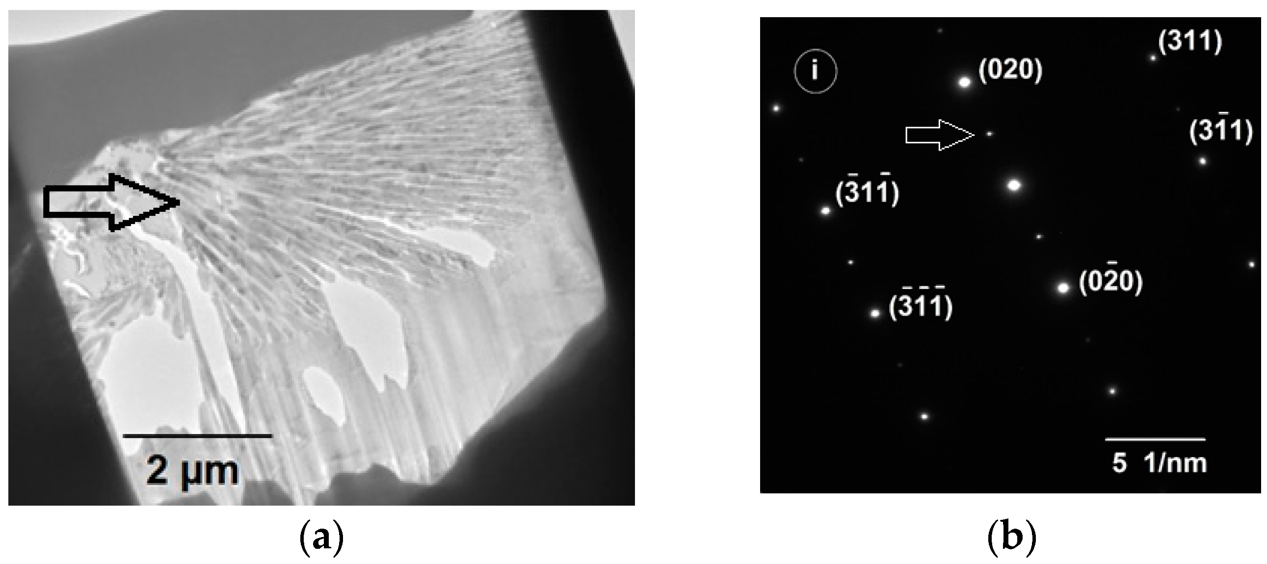
Figure 2a shows a TEM bright field image of a typical spherulite stucture obtained from a FIB milled section of an etched Ni3Ge droplets in the 500–300 μm size fraction. Many fine filament like crystallites radiating out from the centre of the spherulite are clearly visible. A selected area diffraction pattern obtained from the center of a spherulite, at the location marked (i) in Figure 3c, is shown in Figure 2b. Superlattice spots are clearly evident within the diffraction pattern, which would indicate that the material displays at least partial chemical ordering within the spherulites. The same is also true of the featureless background material. However, as we have shown elsewhere [35,36], the dendrite morphologies observed at higher cooling rates (smaller droplets sizes) do not display superlattice spots and are therefore likely to be composed of the chemically disordered material, but still contained within a matrix of ordered phase. From this it is possible to deduce that cooling rates >4600 K s−1, i.e., those obtained in droplets smaller than 212 μm, are sufficient to completely inhibit reordering of material which has grown in the disordered state via disorder trapping.
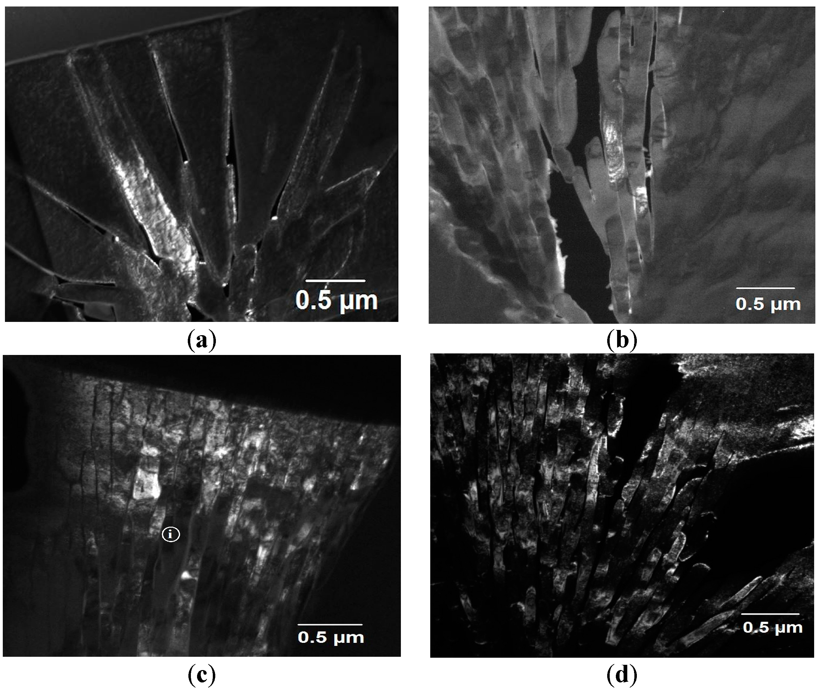
Figure 3a,d presents TEM dark-field images showing detail of the spherulite structures in each of the sieve fractions between ≥850 µm to 300–212 µm. The images were obtained from one of the superlattice spots within the SAD diffraction pattern and as a consequence of this only the chemically ordered material is illuminated. In all cases the spherulites appear to be composed of lamellae of ordered material separated by inter-lamella material of the disordered phase.
This now permits us to make inference both about the origin of the contrast during etching and the solidification pathway giving rise to the spherulite structures. Pertaining to the first point, we surmise that it is the distinction between the ordered and disordered material that gives the topographic contrast during etching, with the ordered material being more resistant to chemical attack. Indeed, given that the material within the droplets is single phase Ni3Ge and is chemically homogeneous it is difficult to conceive what else might give rise to the contrast. With regard to the second point, we note the presence of disordered material within the spherulites which is clearly evident within the dark-field images presented in Figure 3. Given that during equilibrium solidification β-Ni3Ge orders at all temperatures below the melting point this suggests that the material comprising the spherulites must have been subject to some degree of disorder trapping during growth, in turn suggesting that the spherulites grew from the undercooled melt during the recalescence phase of solidification. The volume fraction of spherulitic material within the sample will therefore reflect the solid fraction formed during recalescence, fs, given by fs = ΔT·cp/L, where cp and L are the specific heat and latent heat upon fusion respectively. Following recalescence, solidification of the residual liquid (volume fraction 1 − fs) will occur close to equilibrium and therefore to the ordered form of β-Ni3Ge, giving rise to the matrix material in which the spherulites are embedded. Due to the chemical ordering the matrix is resistant to chemical etching, therefore appearing featureless after etching.
Moreover, these lamellae appear, at least in cases Figure 3b–d, to be of near constant width and cannot all be aligned with the crystallographic directions of an fcc structure. Space-filling appears to be maintained by non-crystallographic branching which can be seen most easily with respect to Figure 3b. In this regard, the spherulites observed here appear quite similar to Category 1 polymer spherulites, although here we appear to be observing a contrast between an ordered and disordered variant of the same crystal structure, rather than between crystalline lamellae in an amorphous matrix as would be the case for polymer spherulites, or indeed those observed in the devitrification of a metallic glass.
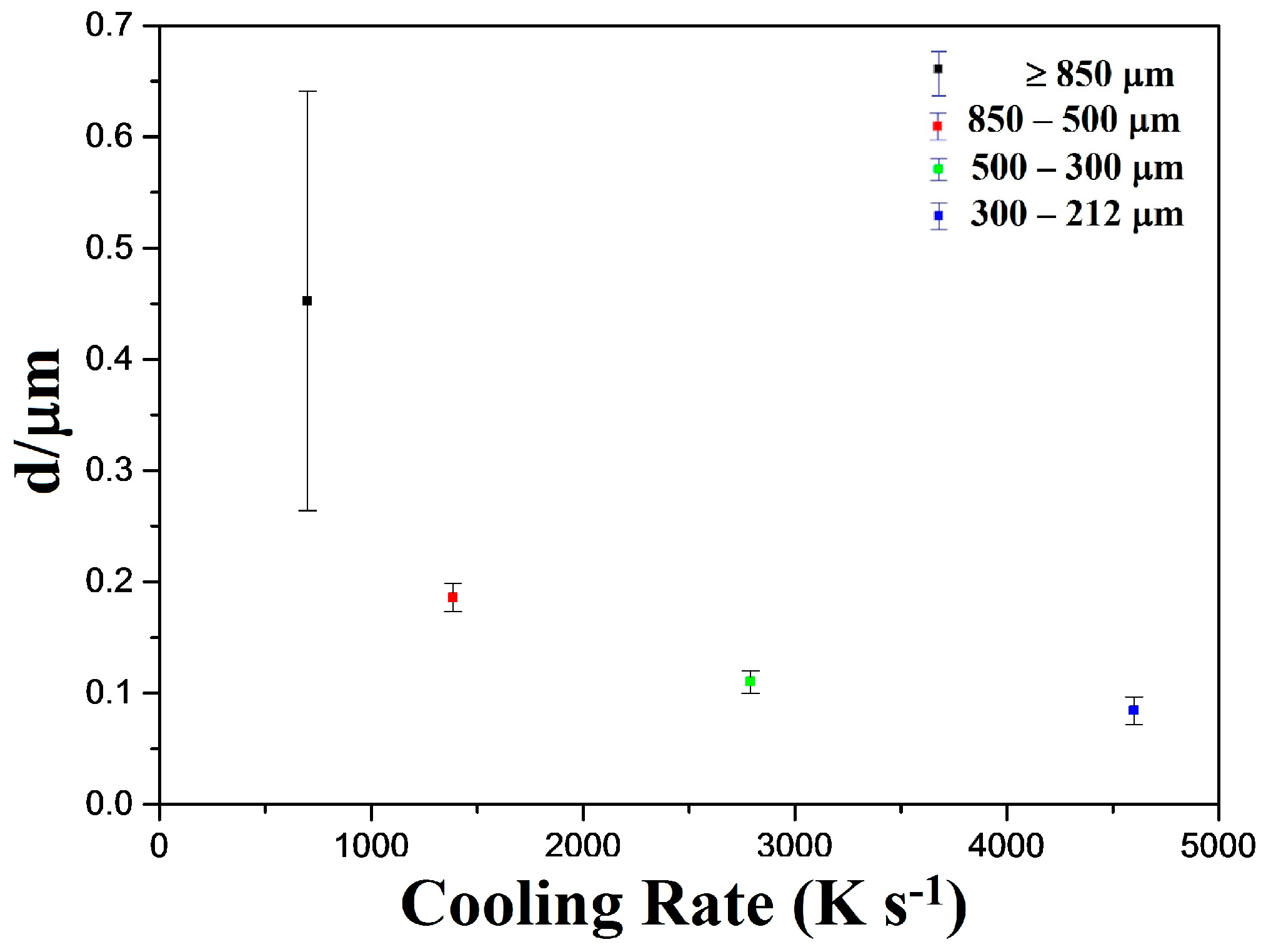
Figure 4 shows the measured lamellar size as a function of drop-tube cooling rate, with the average lamellar size decreasing from 0.45 µm at a cooling rate of 700 K s−1 to 0.11 µm at a cooling rate of 4600 K s−1. The very large error bar corresponding to the measurement for the >850 µm sieve fraction is indicative of the seemingly non-constant lamellar widths observed in this sample, which can be clearly seen in Figure 3a. Notwithstanding this, there is a clear trend for the lamellar width to decrease with decreasing particle size (increasing cooling rate). In these droplets we would expect the melt undercooling to increase with decreasing particle size, both because high cooling rate will, per se, lead to high undercooling and because of the melt sub-division effect, whereby there are a smaller number of potential heterogeneous nuclei in the smaller melt volume. As such there is further correspondence with theoretical models of spherulite formation based on polymeric materials [37], where such a trend has also been observed.
In considering the origin of the spherulite structures revealed during this investigation we consider there are two possible scenarios that may have occurred:
- (1)
- The spherulites grew directly from the melt in the form observed, comprising ordered lamellae. In this case it would seem likely that each lamellae was growing along a preferred crystallographic direction and that this direction differs from one lamellae to the next.
- (2)
- The spherulites grew as the disorder variant of the β-Ni3Ge phase with subsequent ordering in the solid-state. In this case all of the observed lamellae are likely to have grown along the same crystallographic direction but will have distinct chemical ordering.
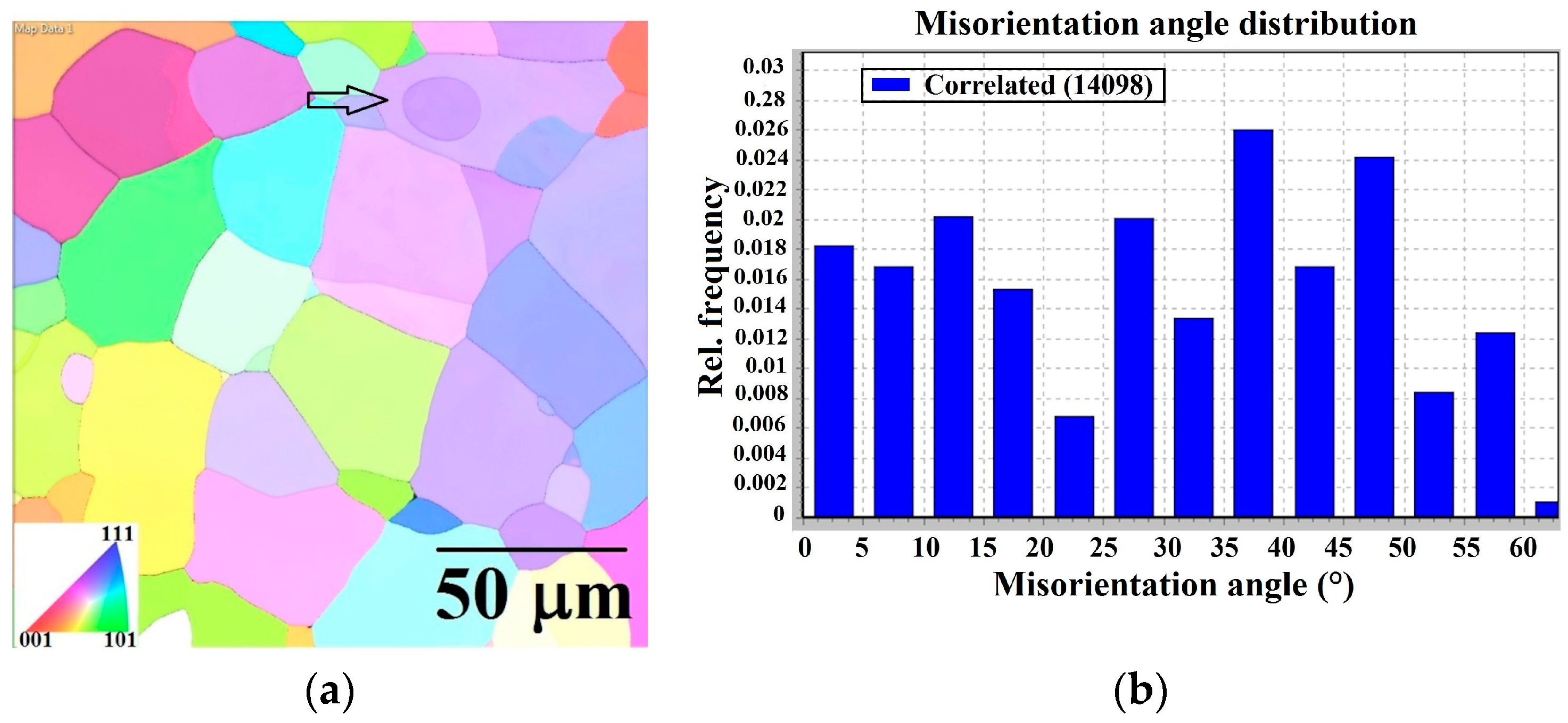
The apparent disintegration of secondary dendrite arms into small spherulite type structures leads us to speculate that (2) is probably more plausible than (1) in this regard, although to further distinguish between the alternatives EBSD analysis has been undertaken on freshly prepared samples, polished using 0.1 μm colloidal silica and without etching. The EBSD phase map for all samples (not shown) further confirms the XRD analysis in that all samples are completely single phase β-Ni3Ge. The grain structure for the 850–500 µm sample is very clearly revealed in the EBSD Euler map as shown in Figure 5a. This shows there are a large number of grains present, these being typically 30–50 µm in diameter. The orientation of each grain relative to its neighbours is random as shown by the histogram of grain orientations (Figure 5b). However, the interesting point to note is that, with one possible exception, discussed below, the spherulites are not visible in EBSD. This is in contrast to the SEM secondary electron images in which it is clear that each grain contains at least one spherulite. As the spherulites in this sample are of a size where they clearly could be resolved by EBSD, the inference of them not being observable is that the crystallography of the spherulites must be contiguous with the grains in which they are embedded. This is also consistent with the TEM diffraction analysis, in which we always observe sharp diffraction spots, consistent the beam being located on a region with a single crystallographic orientation. As such the available is consistent with spherulites growing as a disordered phase, with subsequent solid-state ordering. There is one instance in which a spherulite may be evident in the EBSD map, this appearing as a dark circular region (indicated by the arrow in Figure 5a) in the top right hand corner of the image which is wholly embedded within a grain of a somewhat lighter shade. However, even here, the spherulite has a uniform crystallographic orientation throughout, which would not be consistent with non-crystallographic branching.
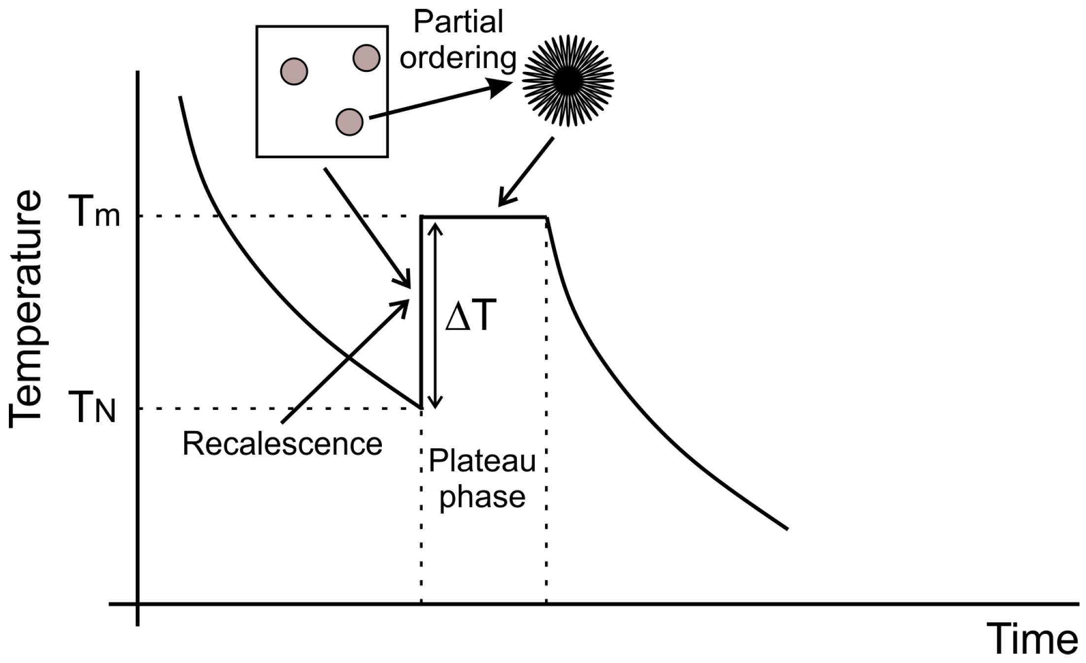
In light of the available evidence a fairly consistent view of spherulite formation in ordered intermetallics at high cooling rate may be formed and is shown schematically in Figure 6. Rapid cooling and the division of the melt into numerous small droplets favours undercooling of the melt by an amount ΔT, with ΔT increasing as the droplets size decreases. At some temperature TN nucleation occurs, initiating the recalescence phase of solidification, during which time growth of the spherulite precursors occurs, probably at this stage as a fully disordered solid due to disorder trapping occasioned by rapid solidification. Shortly after growth of the disordered phase, probably during the plateau phase of solidification in which the solid formed during recalescence coexists with the residual liquid, partial reordering takes place, with ordered filaments growing radially outward from the centre of the crystal leaving a residual disordered material in the space between the filaments. Reordering at this time would be feasible as the temperature of the droplets will again be close to the melting temperature, as commonly observed during the solidification of undercooled melts. Heat extraction from the droplets during the plateau phase results in near isothermal solidification of the residual liquid, which because the process occurs close to equilibrium gives rise to the featureless ordered matrix in which the spherulites are embedded.
Within this process there are many similarities with the growth of spherulites in polymers, including that the width of the filaments is constant within a given spherulite and is a function of cooling rate during growth, with filament width decreasing as cooling rate increases. Moreover, to maintain space-filling the filaments branch at non-crystallographic angles, although in the case of the intermetallics it appears that there is a contiguous underlying crystallography and that the branch is only at the level of the chemical ordering.
3. Materials and Methods
Single phase β-Ni3Ge was produced by arc-melting elemental Ni and Ge (Alfa Aesar (Haverhill, MA, USA), 99.99% and 99.999% purity respectively) together under a protective Ar atmosphere. To ensure homogeneity of the final alloy, the arc-melting process was repeating 8 times with the phase composition of subsequent ingot being confirmed by X-ray diffraction using a PANalytical Xpert Pro (Almelo, Netherlands). Only when the material was confirmed as single phase was drop-tube processing undertaken.
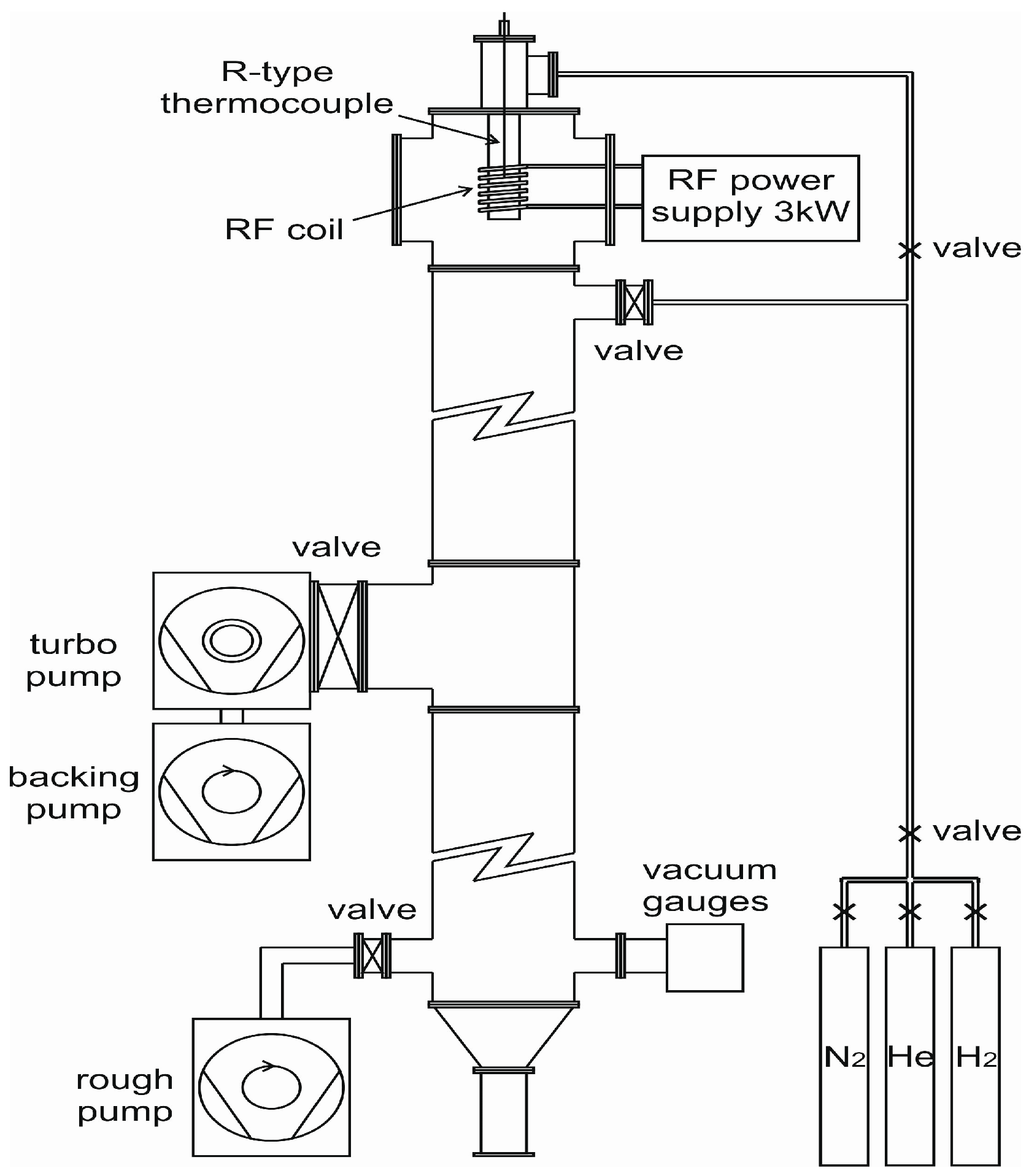
Rapid solidification was affected using a 6.5 m drop-tube (see Figure 7). The alloy sample, of approximately 9.5 g mass, was loaded into an alumina crucible with three, 300 µm, laser drilled holes in the base. Prior to melting the drop-tube was evacuated to a pressure of 2 × 10⁻⁴ Pa and then flushed with N2 gas, with this process being repeated 3 times. The drop-tube was then evacuated to a pressure of 4 × 10⁻⁷ Pa before being filled to 50 kPa with dried, oxygen free N2 gas.
Melting of the sample was by means of induction heating with a graphite susceptor being used for efficient RF (Radiofrequency) coupling given the small mass of metal present. The crucible containing the sample sits fully within the susceptor, which itself sits inside an alumina heat shield. The whole assembly is fixed to the top of the drop-tube via a gas tight seal so that once the desired temperature is attained (1480 K corresponding to 75 K superheat) the melt can be ejected by pressuring the crucible with 400 kPa of N2 gas. Temperature determined was by means of an R-type thermocouple mounted inside the melt crucible, just above the level of the melt.
Once cool the droplets are retrieved from the base of the drop-tube and sieved into standard size fractions between ≥850 μm and ≤38 μm diameter. It is the ≥850 μm to ≤212 μm samples that is the focus of the investigation presented here as the smaller size droplets (d < 212 μm, cooling rate > 4600 K s−1) do not display spherulite type morphologies.
The droplets were subject to XRD analysis to ensure they remained single-phase and were then mounted in transoptic resin and prepared for microstructural analysis. Sample preparation for microstructural analysis involved grinding with SiC grinding media (800–1200 SiC paper) and then polishing with progressively finer grades of diamond paste, started from 6 µm, 3 µm grade, 1 µm and finishing with a 0.25 µm grade. For EBSD analysis a final stage of polishing, using 0.1 µm colloidal silica suspension was also employed, with EBSD being performed on samples that had not been etched.
Following polishing the samples were etched using a mixture of equal parts of HF, HCl and HNO3. A Carl Zeiss (Cambridge, UK) EVO MA15 scanning electron microscope (SEM) operating in secondary electron imaging mode was used to image the microstructure of the droplets revealed by etching while an Oxford Instrument (Abingdon-on-Thames, UK) X-Max Energy-Dispersive X-Ray (EDX) detector was used to check the chemical homogeneity of the samples. Electron backscatter diffraction (EBSD) was performed using a FEI Quanta 650 FEGSEM with EBSD and KE Centaurus system (Hillsboro, OR, USA). Samples were prepared for Transmission Electron Microscope (TEM) analysis using an FEI Nova 200 Nanolab focused ion beam (FIB), with the sections cut being approximately 10 μm × 7 µm and between 55 and 70 nm in thickness. Subsequent analysis was performed using a FEI Tecnai TF20 TEM. The first stage of this analysis was to identify the location of the spherulites using bright-filed imaging, an example of which is shown in Figure 2a. Selected regions within both the spherulites and featureless matrix material were then subject to Selected Area Diffractions (SAD) analysis, with an example SAD pattern being shown in Figure 2b. Finally, given that the SAD patterns showed superlattice spots indicative of chemical ordering, dark-field images were obtained from individual superlattice spots within the SAD pattern. In this manner, only material contributing to the selected diffraction spot, in this case material displaying chemical ordering, contributes to the dark-field image.
4. Summary and Conclusions
Drop-tube processing has been used to rapidly solidify single phase β-Ni3Ge into droplets in four standard sieve size ranges from >850 μm to 300–212 μm. The corresponding range of cooling rates is estimated at 700–4600 K s−1. In the two largest sieve sizes (>850 μm and 850–500 μm) numerous isolated spherulite morphologies are observed with diameters in the range 10–20 μm. In these droplets sizes the spherulites are the only solidification morphology observed in what is otherwise a featureless background. In the smaller two sieve sizes (500–300 μm and 300–212 μm) spherulites coexist with classical dendrites, and structures are observed which consist of linear arrays of spherulites tracing out a dendritic outline. At cooling rates above those investigated here [35] observed that classical dendrite morphologies composed of fully disordered β-Ni3Ge were the only morphology present, with no spherulites being observed. We therefore postulate that the structures composed of arrays of spherulites grew initially as a dendrite of the disordered material during the recalescence phase of solidification. During the ‘plateau phase’ following recalescence, when the solid would have co-existed with the liquid, partial re-ordering then took place, during which time the dendrite arms were fragmented into the observed linear array of spherulites.
Detailed investigation using TEM diffraction analysis and dark-field imaging, combined with EBSD leads us to conclude that these spherulites have many similarities, but also some key difference, to spherulites commonly observed in polymers. The intermetallic spherulites are composed of outward radiating lamellae of near constant width which maintain space filling by branching along non-crystallographic directions. Moreover, the lamellar width is a function of cooling rate, with higher cooling rates giving finer lamellae. In this regard the spherulites observed here closely resemble Category 1 polymer spherulites. However, whereas in a polymer the lamellae would be crystalline in an amorphous matrix, here both lamellae and matrix are crystalline. Indeed, evidence from both TEM and EBSD suggests both share a contiguous underlying crystallography with the distinction being that the lamellae are the chemically ordered L12 variant of this structure while the inter-lamella material is the disordered fcc variant.
Acknowledgments
Nafisul Haque is thankful to the Higher Education Commission (HEC) Pakistan and NED University of Engineering & Technology for financial support.
Author Contributions
Nafisul Haque is a PhD student at the University of Leeds and was responsible for all experimental work undertaken as part of this study and for the initial draft of the manuscript. Andrew Mullis and Robert Cochrane are his PhD supervisors and contributed to the design of the experiments, the analysis and interpretation of the results and the review of the manuscript.
Conflicts of Interest
The authors declare no conflict of interest.
References
- Murarka, S. Metallization: Theory and Practice for VLSI Application; Butterworth-Heinemann: Oxford, UK, 1993. [Google Scholar]
- Cahn, R.; Siemers, P.; Geiger, J.; Bardhan, P. The order-disorder transformation in Ni3 Al and Ni3 Al-Fe alloys—I. Determination of the transition temperatures and their relation to ductility. Acta Metall. 1987, 35, 2737–2751. [Google Scholar] [CrossRef]
- Inoue, A.; Tomioka, H.; Masumoto, T. Microstructure and mechanical properties of rapidly quenched L11 alloys in Ni-Al-X systems. Metall. Trans. A 1983, 14, 1367–1377. [Google Scholar] [CrossRef]
- Assadi, H.; Barth, M.; Greer, A.; Herlach, D.M. Microstructural development in undercooled and quenched Ni3Al droplets. Mater. Sci. Forum 1996, 215–216, 37–44. [Google Scholar] [CrossRef]
- Nash, A.; Nash, P. Binary Alloy Phase Diagrams. In US National Bureau of Standards Monograph Series 25; Springer: New York, NY, USA, 1976; Volume 13, p. 35. [Google Scholar]
- Boettinger, W.; Aziz, M. Theory for the trapping of disorder and solute in intermetallic phases by rapid solidification. Acta Metall. 1989, 37, 3379–3391. [Google Scholar] [CrossRef]
- Ahmad, R.; Cochrane, R.; Mullis, A. Disorder trapping during the solidification of βNi3Ge from its deeply undercooled melt. J. Mater. Sci. 2012, 47, 2411–2420. [Google Scholar] [CrossRef]
- Herlach, D.M. Metastable materials solidified from undercooled melts. J. Phys. 2001, 13, 7737. [Google Scholar] [CrossRef]
- West, J.A.; Aziz, M.J. Kinetic Disordering of Intermetallic Compounds Through First-and Second-Order Transitions by Rapid Solidification. In Ordering and Disordering in Alloys; Springer: Cambrige, MA, USA, 1992; pp. 23–30. [Google Scholar]
- Talbot, W.H.F. On the Optical Phenomena of Certain Crystals. Philos. Trans. R. Soc. Lond. 1837, 127, 25–27. [Google Scholar] [CrossRef]
- Padden, F., Jr.; Keith, H. Crystalline morphology of synthetic polypeptides. J. Appl. Phys. 1965, 36, 2987–2995. [Google Scholar]
- Norton, D.; Keller, A. The spherulitic and lamellar morphology of melt-crystallized isotactic polypropylene. Polymer 1985, 26, 704–716. [Google Scholar] [CrossRef]
- Brewster, D. Transactions of the Royal Society of Edinburgh; Royal Society of Edinburgh: Edinburgh, UK, 1853; Volume 128. [Google Scholar]
- Magill, J. Review spherulites: A personal perspective. J. Mater. Sci. 2001, 36, 3143–3164. [Google Scholar] [CrossRef]
- Keller, A. The spherulitic structure of crystalline polymers. Part I. Investigations with the polarizing microscope. J. Polym. Sci. 1955, 17, 291–308. [Google Scholar] [CrossRef]
- Bunn, C.; Hill, R. Fibres from Synthetic Polymers; Elsevier: Amsterdam, The Netherlands, 1953; p. 253. [Google Scholar]
- Lu, Z.; Goh, T.; Li, Y.; Ng, S. Glass formation in La-based La–Al–Ni–Cu–(Co) alloys by Bridgman solidification and their glass forming ability. Acta Mater. 1999, 47, 2215–2224. [Google Scholar] [CrossRef]
- Cheng, J.; Chen, G.; Gao, P.; Liu, C.; Li, Y. The critical cooling rate and microstructure evolution of Zr41.2Ti13.8Cu12.5Ni10Be22.5 composites by Bridgman solidification. Intermetallics 2010, 18, 115–118. [Google Scholar]
- Aboki, T.; Brisset, F.; Souron, J.; Dezellus, A.; Plaindoux, P. Microstructure studies of Zr65Cu17.5Al7.5Ni10 and Zr65Cu15Al10Ni10 glass forming alloys: Phase morphologies and undercooled melt solidification. Intermetallics 2008, 16, 615–624. [Google Scholar] [CrossRef]
- Chrissafis, K.; Maragakis, M.; Efthimiadis, K.; Polychroniadis, E. Detailed study of the crystallization behaviour of the metallic glass Fe75Si9B16. J. Alloys Compd. 2005, 386, 165–173. [Google Scholar] [CrossRef]
- Yano, T.; Yorikado, Y.; Akeno, Y.; Hori, F.; Yokoyama, Y.; Iwase, A.; Inoue, A.; Konno, T.J. Relaxation and crystallization behavior of the Zr50Cu40Al10 metallic glass. Mater. Trans. 2005, 46, 2886–2892. [Google Scholar] [CrossRef]
- Ziewiec, K. Kinetics of phase transformations in Ni87P13 alloy upon heating. J. Alloys Compd. 2005, 397, 207–210. [Google Scholar] [CrossRef]
- Xia, C.; Xing, L.; Long, W.-Y.; Li, Z.-Y.; Li, Y. Calculation of crystallization start line for Zr48Cu45Al7 bulk metallic glass at a high heating and cooling rate. J. Alloys Compd. 2009, 484, 698–701. [Google Scholar] [CrossRef]
- Liu, J.; Zhang, H.; Fu, H.; Hu, Z.-Q.; Yuan, X. In situ spherical B2 CuZr phase reinforced ZrCuNiAlNb bulk metallic glass matrix composite. J. Mater. Res. 2010, 25, 1159–1163. [Google Scholar] [CrossRef]
- Sun, H.; Flores, K. Microstructural analysis of a laser-processed Zr-based bulk metallic glass. Metall. Mater. Trans. A 2010, 41, 1752–1757. [Google Scholar] [CrossRef]
- Sun, H.; Flores, K.M. Spherulitic crystallization behavior of a metallic glass at high heating rates. Intermetallics 2011, 19, 1538–1545. [Google Scholar] [CrossRef]
- Sun, H.; Flores, K.M. Spherulitic crystallization mechanism of a Zr-based bulk metallic glass during laser processing. Intermetallics 2013, 43, 53–59. [Google Scholar] [CrossRef]
- Keith, H.; Padden, F., Jr. A phenomenological theory of spherulitic crystallization. J. Appl. Phys. 1963, 34, 2409–2421. [Google Scholar] [CrossRef]
- Morse, H.W.; Warren, C.H.; Donnay, J.D.H. Artificial spherulites and related aggregates. Am. J. Sci. 1932, 137, 421–439. [Google Scholar] [CrossRef]
- Morse, H.; Donnay, J. Optics and structure of three-dimensional spherulites. Am. Mineral. 1936, 21, 391–427. [Google Scholar]
- Gránásy, L.; Pusztai, T.; Tegze, G.; Warren, J.A.; Douglas, J.F. Growth and form of spherulites. Phys. Rev. E 2005, 72, 011605. [Google Scholar] [CrossRef] [PubMed]
- Swallen, S.F.; Bonvallet, P.A.; McMahon, R.J.; Ediger, M. Self-diffusion of tris-naphthylbenzene near the glass transition temperature. Phys. Rev. Lett. 2003, 90, 015901. [Google Scholar] [CrossRef] [PubMed]
- Masuhr, A.; Waniuk, T.; Busch, R.; Johnson, W. Time scales for viscous flow, atomic transport, and crystallization in the liquid and supercooled liquid states of Zr41.2Ti13.8Cu12.5Ni10.0Be22.5. Phys. Rev. Lett. 1999, 82, 2290. [Google Scholar] [CrossRef]
- Bisault, J.; Ryschenkow, G.; Faivre, G. Spherulitic branching in the crystallization of liquid selenium. J. Cryst. Growth 1991, 110, 889–909. [Google Scholar] [CrossRef]
- Haque, N.; Cochrane, R.F.; Mullis, A.M. Rapid solidification morphologies in Ni3Ge: Spherulites, dendrites and dense-branched fractal structures. Intermetallics 2016, 76, 70–77. [Google Scholar] [CrossRef]
- Haque, N.; Cochrane, R.F.; Mullis, A.M. Disorder-order morphologies in drop-tube processed Ni3Ge: Dendritic and seaweed growth. J. Alloys Compd. 2016, in press. [Google Scholar] [CrossRef]
- Crist, B.; Schultz, J.M. Polymer spherulites: A critical review. Prog. Polym. Sci. 2016, 56, 1–63. [Google Scholar] [CrossRef]
Figure 1.
SEM micrographs of HF etched drop-tube processed Ni3Ge droplets: (a,b) shows presence of spherulites microstructure from the ≥850 μm and 850–500 μm sieve size fraction respectively; (c,d) shows co-existence of spherulites with dendritic microstructure in the drop-tube samples of size 500–300 μm and 300–212 μm respectively.
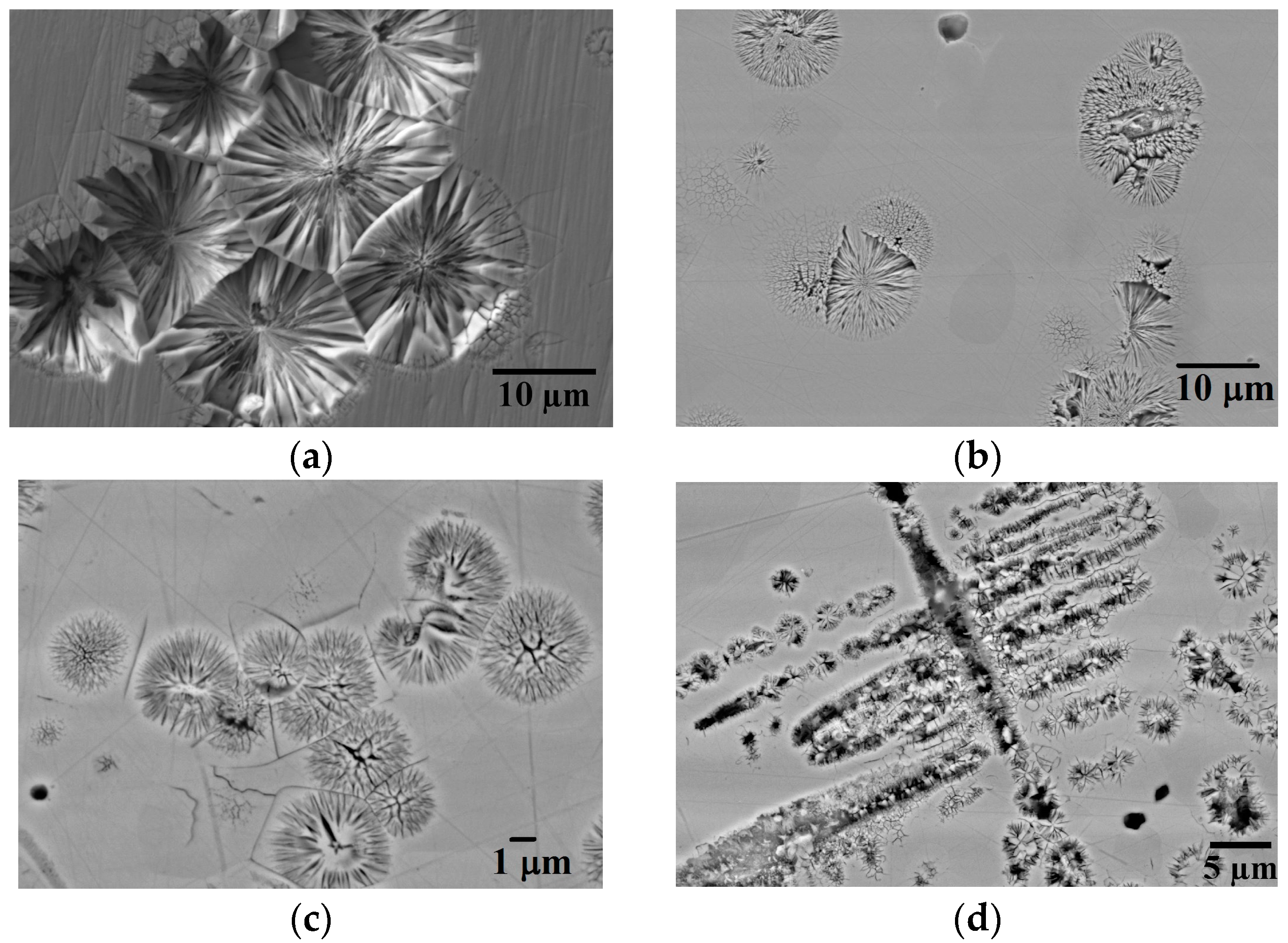
Figure 2.
(a) Transmission Electron Microscope (TEM) bright-field image of a spherulite structure (indicated by an arrow) in the 300–212 μm size fraction; (b) TEM selected area diffraction pattern of one of the spherulites shown in Figure 1c (zone axis [−1 0 3]). Arrow shows the specification of the spot from which the dark field image obtained within Figure 1c.

Figure 3.
TEM dark-field image of HF etched drop-tube processed Ni3Ge droplets obtained from one of the superlattice spots within the diffraction pattern of drop-tube samples, (a) ≥850 μm; (b) 850–500 μm; (c) 500–300 μm and (d) 300–212 μm respectively.
Figure 3.
TEM dark-field image of HF etched drop-tube processed Ni3Ge droplets obtained from one of the superlattice spots within the diffraction pattern of drop-tube samples, (a) ≥850 μm; (b) 850–500 μm; (c) 500–300 μm and (d) 300–212 μm respectively.

Figure 4.
Average spherulite lamellar width as a function of cooling rate.

Figure 5.
(a) Electron backscatter diffraction (EBSD) result of Euler texture map of drop-tube sample size 850–500 μm (arrow indicate presence of spherulite); (b) Histogram of the correlated misorientation angle distribution across grain boundaries for the image shown in (a).
Figure 5.
(a) Electron backscatter diffraction (EBSD) result of Euler texture map of drop-tube sample size 850–500 μm (arrow indicate presence of spherulite); (b) Histogram of the correlated misorientation angle distribution across grain boundaries for the image shown in (a).

Figure 6.
Schematic diagram showing proposed model for spherulite formation in β-Ni3Ge with initial growth to the disordered phase during the recalescence phase of solidification followed by partial reordering during the plateau phase.
Figure 6.
Schematic diagram showing proposed model for spherulite formation in β-Ni3Ge with initial growth to the disordered phase during the recalescence phase of solidification followed by partial reordering during the plateau phase.

Figure 7.
Schematic diagram of the drop-tube apparatus used in this study.

© 2017 by the authors. Licensee MDPI, Basel, Switzerland. This article is an open access article distributed under the terms and conditions of the Creative Commons Attribution (CC BY) license (http://creativecommons.org/licenses/by/4.0/).
Share and Cite
MDPI and ACS Style
Haque, N.; Cochrane, R.F.; Mullis, A.M. Morphology of Spherulites in Rapidly Solidified Ni3Ge Droplets. Crystals 2017, 7, 100. https://doi.org/10.3390/cryst7040100
AMA Style
Haque N, Cochrane RF, Mullis AM. Morphology of Spherulites in Rapidly Solidified Ni3Ge Droplets. Crystals. 2017; 7(4):100. https://doi.org/10.3390/cryst7040100
Chicago/Turabian StyleHaque, Nafisul, Robert F. Cochrane, and Andrew M. Mullis. 2017. "Morphology of Spherulites in Rapidly Solidified Ni3Ge Droplets" Crystals 7, no. 4: 100. https://doi.org/10.3390/cryst7040100
Note that from the first issue of 2016, this journal uses article numbers instead of page numbers. See further details here.