
Technology, Preparation and Properties of the Cast Glass-Coated Magnetic Microwires

1
Institute of Applied Physics, Academy of Sciences of Moldova, 5, Academy str., Kishinev MD-2028, Moldova
2
AMOTEC Ltd., 47, Titulescu str., 3th Apartment, Kishinev MD-2032, Moldova
3
MFTI Ltd., 26 Gurie Grosu str., 39th Apartment, Kishinev MD-2021, Moldova
*
Author to whom correspondence should be addressed.
Crystals 2017, 7(6), 136; https://doi.org/10.3390/cryst7060136
Submission received: 9 January 2017
/
Revised: 3 May 2017
/
Accepted: 5 May 2017
/
Published: 29 May 2017
(This article belongs to the Special Issue Advance in Crystalline Thin Wires)
Abstract
:Magnetic properties of cast amorphous and nanocrystalline microwires have been reviewed considering their potential application. Microwires were produced from Co Fe Mn Cr Cu B and Si using the Taylor–Ulitovsky method. Technological aspects of the Taylor–Ulitovsky method for fabrication of glass-coated microwire with different structure are analyzed. Magnetic microwires demonstrate a large variety of magnetic behaviors, which is important for sensing applications. Depending on the chemical composition of the metallic core, for Co-, Fe- and Ni-based composition, the microwires’ properties are very different. The geometrical characteristics (diameter of metallic core and thickness of the glass) of the microwire depend on the physical properties of a metallic composition and of glass and the parameters of the heating inductor and the speed of obtaining a microwire. The diameter of metallic core in these microwires can range from 0.5 to 70 μm, and their thickness of the glass can vary from 1 to 50 μm.
1. Introduction
Cast glass-coated amorphous micro- and nanowires (CGCAMNW) are very interesting materials from a theoretical standpoint as well as for the practical applications.
A simple production technology of cast glass-coated amorphous micro- and nanowires (CGCFMWs) was first introduced in 1924 by Taylor [1]. Later, in the period 1950–1964, this method was significantly modified by Ulitovsky. Modified Taylor–Ulitovsky method allows producing large amounts of such microwires. Interest in the cast glass-coated microwires has greatly increased over the last few years, mainly due to their technological applications, in particular, as sensor elements in various devices [2,3]. Consequently, preparation of CGCFMWs by the Taylor–Ulitovsky method and the study of their magnetic properties were reported in many publications by various research groups [2,3,4,5,6,7,8,9,10,11,12,13,14,15,16,17,18,19,20,21,22,23,24,25,26,27,28,29]. It is essential that the microwires are manufactured using a rapid solidification technique. However, the main peculiarity of the aforementioned microwires is the simultaneous rapid solidification of metallic alloy covered by glass [2,3,4,5,6,7,8,9].
Therefore, the other families of amorphous magnetic wires produced by co-called “in-rotating-water quenching” or melt-extraction methods present the distinctive magnetic properties since their magnetoelastic anisotropy and magnetic domain structures are different.
Technological aspects of the Taylor–Ulitovsky method for the production of the cast glass-coated microwires, which can have the different microstructure and composition of the metallic core, are presented below. If a continuous production process of casting glass-coated amorphous magnetic microwires is carried out, a metal alloy rod (named LM) is inserted into the glass tube 1.
In this process, a few grams of the metallic alloy are placed inside a glass tube located directly within a high frequency induction heater (see Figure 1). The metallic alloy is heated up to the melting point to form a droplet. Under suitable conditions the molten metal fills the glass capillary and so a microwire is formed when its metallic core is completely coated with a glass cladding. In order to regulate the diameter of the microwire’s metallic core, a vacuum controller is used to regulate the pressure inside the glass tube. Thus, the geometrical characteristics of the obtained microwires are determined not only by the physical properties of the glass and the metal, but also by the diameter of the initial glass tube, and the parameters of the heating inductor. The microstructure and, hence, properties of the manufactured microwire mostly depend on the cooling rate, which can be controlled by a cooling mechanism, by which the metal-filled capillary enters into a stream of a cooling liquid (water or oil) on its way to the receiving coil. The magnetic properties of the microwire are largely attributed to the composition and microstructure of the metallic core. The casting method offers the possibility of fast cooling and solidification of a liquid metal in a nonequilibrium process, which leads to the formation of various metastable metal phases. Depending on the critical cooling rates, different metastable metal phases can be formed: the supersaturated solid solution, nanocrystalline, microcrystalline and crystalline phases. The values of the critical quenching (cooling) rates that gives rise to a metastable (or supersaturated) state of the microwire metallic core are 104–107 K/s [2,6,7].
The main advantages of this method for the production of the cast glass-coated microwires are as follows [2,3,5,6,7]:
- The production of the continuous long pieces of a microwire up to 104 m (in the case of a drip process). For a continuous process (see Figure 1), the length of a microwire is not limited.
- A wide range of variations in the geometric parameters (typically the metallic core diameter Dm is in a range of 0.5–70 µm, and a glass-coating thickness is in a range of 1–50 µm (Figure 2)).
- The control and adjustment of the geometric parameters (the inner metallic core diameter Dm and glass thickness) during production.
- The reproducibility of the physical properties and geometric parameters of the microwires in mass production.
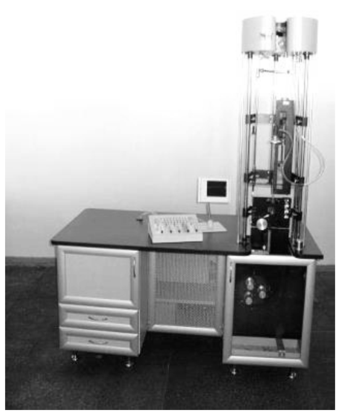
Figure 3 shows the machine for the preparation of CGCFMWs by the Taylor–Ulitovsky method, which were manufactured in Moldova. This machine can produce cast glass-coated microwires of different types with a broad range of the core diameters, as was indicated above.
We also provided an analysis of residual stresses arising in glass-coated microwires and reviewed the prospective applications of glass-coated microwires (see below).
2. Experimental Installation for Measuring Magnetic Properties
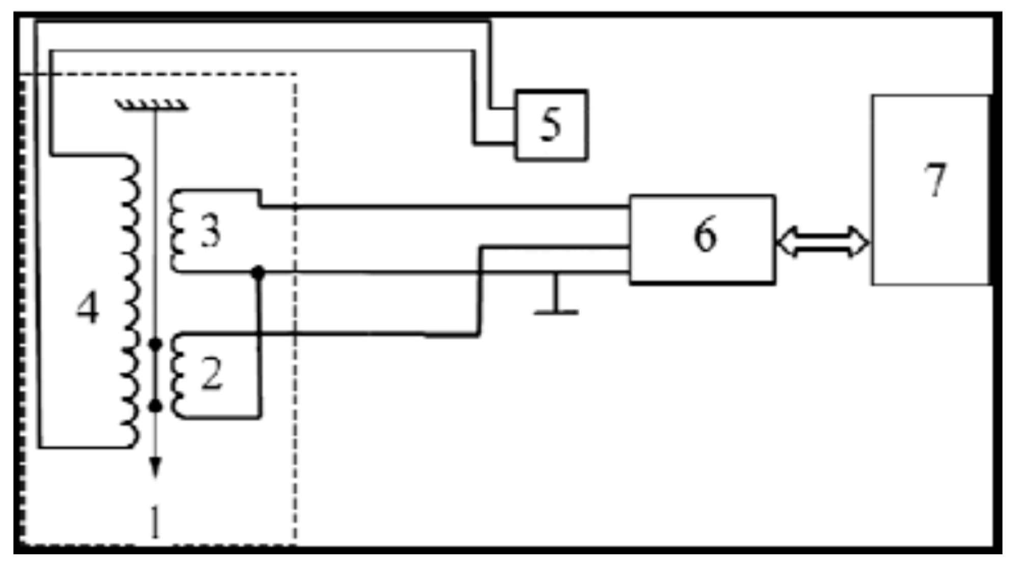
An installation has been developed for measuring of magnetic properties of microwires. The magnetic loops of sample 1 were measured by the standard induction method (Figure 4). Pickup (2) the magnetic loops of sample 1 were measured by the standard induction method (Figure 4).
Pickup (2) and compensating (3) coils were placed symmetrically in magnetizing coil 4 (connected to a linear-sweep power supply 5) in which a magnetic field from 0 to 10 Oe with a frequency of 10–60 Hz was created.
The analog differential signal from the pickup coil (after compensation in switching unit 6) was digitized and integrated in unit 7 to the shape of the integral hysteresis curve. The correctness of the integration process was verified with known reference specimens and compensating (3) coils were placed symmetrically in magnetizing coil 4 (connected to a linear-sweep power supply 5) in which a magnetic field from 0 to 10 Oe with a frequency of 10–60 Hz was created.
The analog differential signal from the pickup coil (after compensation in switching unit 6) was digitized and integrated in unit 7 to the shape of the integral hysteresis curve. The correctness of the integration process was verified with known reference specimens.
3. The Effect of Heat Treatment on the Coercive Force
Annealing (with the annealing time sufficient for the relaxation of the amorphous structure) up to the temperature when the process of formation of micro-nano crystals starts (~400 °C) is of practical interest. Residual stresses relaxation by annealing can produce irreversible changes of magnetic properties (i.e., coercive field, Hc) allowing optimization of magnetic properties of microwires. At temperatures above 400 °C, the formations of a nano- or microcrystalline phases in CGCFMWs were observed (this temperature is designated as Tcr) [11,12,13,14,15,16,17].
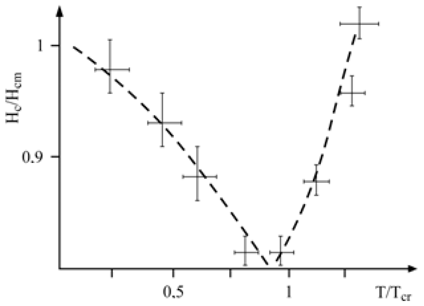
Figure 5 shows a typical dependence of the coercive field on annealing temperature reflecting the relaxation of the residual stresses and first stages of the crystallization processes. It is worth noting that in some compositions of magnetic microwires the heat treatment at temperatures below Tcr can improve the CGCFMWs magnetic properties, i.e., decrease the values of σH and Hc [14,15,16].
Dependence provided in Figure 5 is similar to that reported by the other authors (see [11,12,13,14,15,16,17,18]).
The compositions that we have used are characterized by a high thermal stability; i.e., by a sufficiently high Tcr-value. In the present study, we used the specimens with the glass coating thickness of about (7–10) μm. The coercive force, Hcm is varied in the range of (0.5–1.5) Oe at room temperature. In spite of a quite broad range of initial Hcm-values, the correlation of Hc/Hcm remains unchanged within the error bars (-up to 20%) and fits within the dependence shown in Figure 5 [5,6,7,8].
The structure of the nanocrystalline alloy consists of nanometric grains, with average size about 10 nm, embedded in the residual amorphous matrix. Properties of alloys at the nanoscale depend on the composition, size of constituting nanocrystals, as well as on their distribution within the amorphous phase [11,12,13,14,15,16,17]. Microwires with hard magnetic properties can be obtained by suitable thermal treatments (see Figure 6).
On the basis of Becker–Volmer theory, the following approximate expression holds:
where: exp{E1,2/kT}, describes the low-temperature processes with the energy of activation E1,2.
Hs/Hsm ~ exp{E1,2/kT}/[1 + exp{−G/kТ}]
The expression:
describes high-temperature processes, for which G is the change in the Gibbs energy, of irreversible phase transitions associated with the crystallization.
{1/[1 + exp{−G/kТ}}
In the classical nucleation theory (of Becker–Volmer), an inverse value is generally used, which determines the rate of the nucleation.
For the theoretical description of the above phenomena Formula (1) can be generalized for the case of structural changes.
At low temperatures, the value of exp{−G/kT} is small (as-compared to a unity); therefore, formula:
can be used.
Hs/Hsm ~ exp{E1,2/kT}
At high temperatures, Formula (1) can be written as follows:
Hs/Hsm ~ exp{E1,2/kT}exp{G/kT}
The main dependence is now determined by the product exp (G/kT), determining the irreversible relaxation. Note that the proposed model allowing suggesting that
where S1 is the entropy change decreasing with the relaxation of the initial amorphous state into more stable one but also amorphous state, and S2 is the entropy change increasing during the transition from the metastable state to the stable polycrystalline state.
G(T) ~ T (S1 + S2)
Consequently, with the entropy increasing, the system passes into a more stable state. Therefore, the variation of the switching field also decreases. Thus, the generalization of the presented equation can be justified on the thermodynamic basis.
The result provided here as a proof of a stronger dependence of Hc for the irreversible processes that are described by the exp (G/kT) product during the high-temperature treatment.
Regardless of the application, in designing inductive components, the use of nanocrystalline cores typically provides the following advantages [11,12,13,14,15,16,17,18,19,20]:
- Reduced weight
- Reduced losses on the coil due to reduction in number of turns
- Extended temperature range
- Increased durability and stability of properties.
- High accuracy for measuring devices
4. Evaluation of Residual Stresses
The main technological parameters for the production of the glass-coated microwires are presented below.
According to the previous analysis [6], the most significant effect on the geometry of such microwire comes from the glass properties. The microwire radius Rg (the outer radius of the glass shell) is estimated as follows:
where k is the parameter, which is dependent on a casting rate (0 < k < 1); ρ is the average microwire density; Vd is the casting rate; σs is the surface tension; and η is the dynamical viscosity of the glass:
where ε ~ 2·10 kJ/mol, ΔH ~ 102 kJ/mol, R is the universal gas constant, η0 and c are the material constants (c ~ 0.4–0.9).
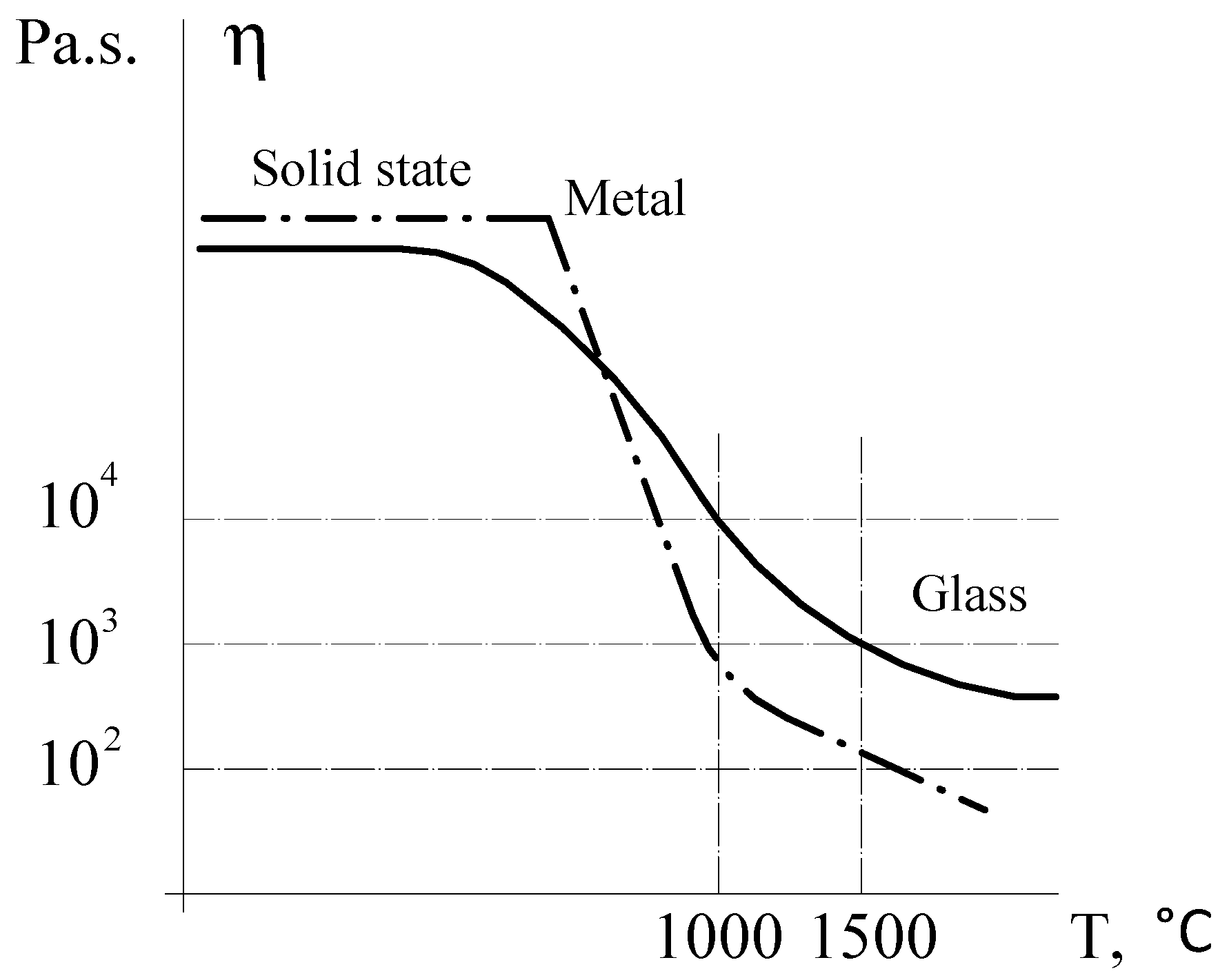
Special attention is paid to the parameters determining the casting and cooling rates that are responsible for the microstructure of the cast glass-coated microwires. So, the dynamical viscosity η is very important parameter whose value has characteristic temperature dependence. A typical temperature dependence of the dynamical viscosity is shown below in Figure 7. The temperature region where the casting process can be implemented is indicated by the dashed lines.
Formula (6) suggests the following:
- If the casting rate is sufficiently high, we obtain for Rc:where k = 2/3.
- At the theoretical limit of extremely high casting rate, i.e., when k→1, we obtain:
Finally, we present the results on theoretical simulation for the residual stresses in the microwire metallic core. The origin of the residual stresses is a difference in the thermal expansion coefficients of a metal and of glass. A simple theory for the distribution of the residual stresses in the metallic core of the microwire was proposed in the works [4,5,6,7,8,9,10,11].
In cylindrical coordinates, the residual stresses are characterized by the axial, radial and tangential components which, at a first approximation, do not depend on the radial coordinate [5,6,7,8,9]:
where Rm is the metallic core radius of microwire;
where Ym is the Young’s modulus of metal and Yg is the Young’s modulus of glass:
where αm and αg are the thermal expansion coefficients of the metal and glass, respectively; T* is the effective solidification temperature of the composite microwire (when both the metallic core and the glass-coating (cladding) are solidified) and T is the experimental temperature.
We will provide below the more accurate model used for the residual stresses at the microwires.
The metallic strand from its axis up to the certain internal radius b preserves the liquid state (parameter b has a certain value depending on the defined metallic alloy composition and cooling rate).
In contrast, the metallic core from b up to Rm, which has only the elastic residual stresses, freezes earlier.
2. In addition, at r < b, this model gives (see [5,8]):
where K is the thermoelastic constant of metal.
(Note that a rigorous solution should be obtained by the lacing of Formulas (11)–(16) (see [5])).
5. Application of Microwires
The microwire are of great importance in a wide spectrum of applications, most of which are related to wireless telecommunications systems, such as telephone, broadcast satellite television, or satellite global positioning. Radar systems are also very useful for detecting mobile targets in air, sea for air-traffic control or missile tracking radars, and for a wide variety of remote sensing systems. In addition, resonance phenomena appearing at microwave frequencies offer an opportunity for novel applications in systems medical diagnosis and treatment or just new effects in basic science. In all these cases, the involved phenomena are characterized by high frequency electromagnetic waves.
The glass-coating for the magnetic microwires, in addition to protecting the metallic nucleus from corrosion and providing electrical insulation, induces large mechanical stresses in the metallic nucleus [2,3,4,5,6,7,8,9].
They can exhibit an exciting microwave behavior exploited in numerous technological applications requiring elements for absorption of electromagnetic radiation.
The composite prepared from magnetically soft glass-coated microwires embedded in an elastomeric matrix are promising for applications in electromagnetic shields (see Figure 9 and Figure 10) [18,19,20,21,22,23,24,25]. Thus, 1-mm-thick shields are capable for attenuating of electromagnetic radiation in a frequency range of 3–16 GHz by 20–30 dB, which can be used in aircraft equipment operating in the super high frequency range, e.g., radar altimeters (4.3 GHz), microwave landing systems (5.0–5.1 GHz), Doppler navigation systems (8.8 GHz), and weather radars (9.375 GHz). Other advantages of such shields are their excellent mechanical flexibility due to the elastomeric matrix as well as good adherence to various surfaces.
The absorbing characteristic of a screen made from microwires with natural resonance in the range of frequencies 10–12 GHz [5,9] are as follows: the measurement error was less than 10% for the frequency, while the spread of the attenuation factor was 5–7 dB.
As we mentioned above, the glass-coated microwires have physical properties that are tuneable by the composition and microstructure of the metallic core. These are the functional materials that can be used as both individual materials and fillers for the composites. For example, the glass-coated microwires can possess excellent magnetic properties (Giant magnetoimpedance effect of fast magnetizxation switching) that make them very suitable as the sensing elements of devices for diverse technological applications [17,26,27,28,29].
It has been established that the bistability of glass-coated micro- and nanowires fully correlates with natural ferromagnetic resonance (NFR). The lower the NFR frequency is, the smaller the coercive force is [5,9]. In fact, low–NFR-frequency glass-coated micro- and nanowires can be used as magnetic field sensors that use the so-called asymmetric giant magneto-impedance (GMI) effect (see [17,18,19,25,26,27]). We accept that the asymmetric GMI is equivalent to the NFR with a sufficiently small natural ferromagnetic resonance frequency.
The glass-coated ferromagnetic microwires embedded in a cellulose matrix can be used as validating elements in security devices for autentification of a counterfeit products. For instance, use of specially designed detectors for sensing of the ferromagnetic microwires in paper can be suitable for the autentification of documents. The geometry of the microwires prepared from soft magnetic alloys is compatible with the size of the cellulosic fibers.
Glass-coated microwires embedded in different matrices have already found numerous applications in: miniaturized high-voltage transformers, elements for magnetic encoding, the sensitive elements of magnetic sensors, electromagnetic shields, anti-shoplifting labeling, security elements for authentication of products and documents, access control points, and floor heating systems, etc.
6. Conclusions
We described the main technological parameters for the production of the cast glass-coated microwires. The continuous casting method for glass-coated microwires (Taylor–Ulitovsky method) has some limitations determined by the physical properties of a metal and of glass. A range of the working temperatures for casting is specific for the given composition of a metallic alloy and a certain type of glass, i.e., for each pair of a metallic alloy and glass, the working temperature depends on the viscosity of the glass and the metal and on other physical properties.
Particular attention has been paid to the parameters determining a microstructure of the cast glass-coated microwires (crystalline, microcrystalline, or nanocrystalline).
We have written simple analytic expressions for the residual stresses in the microwire metallic core, which clearly show their dependence on the ratio of the microwire radius to the metallic nucleus radius and on the ratio of the Young’s modules of the glass and metal (see Formulas (11)–(14)). The theoretical simulation in accordance with the thermoelastic relaxation theory show that the residual stresses increase from the axis of microwire up to the surface of its metallic core, which corresponds to the previously obtained experimental data. Thus, at the preparation of the cast glass-coated microwires by the Taylor–Ulitovsky method, the residual stresses attain the maximum values on the metallic core surface. This theory also explains the activation mechanism of the domain wall motion in the cast glass-coated microwires, giving the Arrhenius temperature dependence for the magnetic coercivity.
The specific feature of the cast glass-coated microwires is a presence of the residual stresses arising from a difference of the thermal expansion coefficients of the metallic alloy and the glass-coating. This feature is the main factor determining the physical properties of such microwires, particularly their magnetic properties.
As a result, the cast glass-coated ferromagnetic microwires exhibit a residual magnetization due to a specific distribution of the residual stresses. This property of the studied microwires can be used for a design of the long-term magnetic storage elements and other electronic devices based, for example, on the domain wall propagation.
We have overviewed the applications of glass-coated microwires in composites for absorption characteristics of shielding. We assume that the main property micro- and nanowires is magnetization reversal bistability in cast glass-coated micro- and nanowires. Glass-coated micro- and nanowires bistability can be explained using theories designed for calculating residual stresses.
Acknowledgments
This work was supported by the CSSDT of the Academy of Sciences of Moldova (Projects 15.817.02.03A) The authors are grateful to A. Yelon, D. Menard, M. Vazquez and especially A. Zhukov.
Author Contributions
Serghei A. Baranov designed the concept of the project, Vladimir S. Larin and Alexander V. Torcunov contributed to development of glass-coated technology, Serghei A. Baranov, Vladimir S. Larin and Alexander V. Torcunov measured the magnetic properties and developed the applications of glass-coated microwires. Serghei A. Baranov prepared the main manuscript and performed the theoretical analysis of the experimental results. All the authors participated in the result discussion and manuscript preparation. All the authors reviewed and finalized the manuscript.
Conflicts of Interest
The authors declare no conflict of interest.
References
- Taylor, G.F. A method of drawing metallic filaments and a discussion of their properties and uses. Phys. Rev. 1924, 23, 655–660. [Google Scholar] [CrossRef]
- Vazquez, M. Handbook of Magnetism and Advanced Magnetic Materials; Kronmuller, H., Parkin, S., Eds.; John Wiley and Sons: New York, NY, USA, 2007; Volume 4, pp. 2193–2226. [Google Scholar]
- Zhukov, A.; Vázquez, M.; Velázqez, J.; Hernando, A.; Larin, V. Magnetic properties of Fe-based glass-coated microwires. J. Magn. Magn. Mater. 1997, 170, 323–330. [Google Scholar] [CrossRef]
- Zuberek, R.; Szymczak, H.; Gutowski, M.; Zhukov, A.; Zhukova, V.; Usov, N.A.; Garcia, K.; Vazquez, M. Internal stress influence on FMR in amorphous glass-coated microwires. J. Magn. Magn. Mater. 2007, 316, e890–e892. [Google Scholar] [CrossRef]
- Baranov, S.A. Magnetic models of cast microwires. Surf. Eng. Appl. Electrochem. 2011, 47, 316–330. [Google Scholar] [CrossRef]
- Larin, V.S.; Torcunov, A.V.; Zhukov, A.; Gonzalez, J.; Vazquez, M.; Panina, L. Preparation and properties of glass-coated microwires. J. Magn. Magn. Mater. 2002, 249, 39–45. [Google Scholar] [CrossRef]
- Sinnecker, E.H.C.P.; Páramo, D.; Larin, V.; Zhukov, A.; Vázquez, M.; Hernando, A.; González, J. Glass coated microwires with enhanced coercivity. J. Magn. Magn. Mater. 1999, 203, 54–56. [Google Scholar] [CrossRef]
- Baranov, S.A.; Laroze, D.; Vargas, P.; Vazquez, M. Domain structure of Fe-based microwires. Phys. B 2006, 372, 324–327. [Google Scholar] [CrossRef]
- Baranov, S.A.; Yamaguchi, M.; Garcia, K.L.; Vazquez, M. Dimensional absorption high-frequency properties of the cast glass coated microwires. Surf. Eng. Appl. Electrochem. 2008, 44, 245–247. [Google Scholar] [CrossRef]
- Antonov, A.S.; Borisov, V.T.; Borisov, O.V.; Prokoshin, A.F.; Usov, N.A. Residual Quenching Stresses in Glass-Coated Amorphous Ferromagnetic Microwires. J. Phys. D Appl. Phys. 2000, 33, 1161–1168. [Google Scholar] [CrossRef]
- Peng, H.X.; Qin, F.X.; Phan, M.H.; Tang, J.; Panina, L.V.; Ipatov, M.; Zhukova, V.; Zhukov, A.; Gonzalez, J. Co-based magnetic microwire and field-tunable multifunctional macro-composites. J. Non-Cryst. Solids 2009, 355, 1380–1386. [Google Scholar] [CrossRef]
- Vazquez, M.; Zhukov, A.; Pirota, K.R.; Varga, R.; Garcia, K.L.; Luna, C.; Provencio, M.; Navas, D.; Martınez, J.L.; Hernandez-Velez, M. Temperature dependence of remagnetization process in bistable magnetic microwires. J. Non-Cryst. Solids 2003, 329, 123–130. [Google Scholar] [CrossRef]
- Zhukov, A.; Chichay, K.; Talaat, A.; Rodionova, V.; Blanco, J.M.; Ipatov, M.; Zhukova, V. Manipulation of magnetic properties soft glass-coated microwires by annealing. J. Magn. Magn. Mater. 2015, 383, 232–236. [Google Scholar] [CrossRef]
- Zhukov, A.; Ipatov, M.; Talaat, A.; Blanco, J.M.; Hernando, B.; Gonzalez-Legarreta, L.; Suñol, J.J.; Zhukova, V. Correlation of Crystalline Structure with Magnetic and Transport Properties of Glass-Coated Microwires. Crystals 2017, 7, 41. [Google Scholar] [CrossRef]
- Zhukov, A.; Churyukanova, M.; Kaloshkin, S.; Semenkova, V.; Gudoshnikov, S.; Ipatov, M.; Talaat, A.; Blanco, J.M.; Zhukova, V. Effect of annealing on magnetic properties and magnetostriction coefficient of Fe-Ni-based amorphous microwires. J. Alloys Compd. 2015, 651, 718–723. [Google Scholar] [CrossRef]
- Zhukova, V.; Cobeno, A.F.; Zhukov, A.; Blanco, J.M.; Puerta, S.; Gonzalez, J.; Vazquez, M. Tailoring of magnetic properties of glass-coated microwires by current annealing. J. Non-Cryst. Solids 2001, 287, 31–36. [Google Scholar] [CrossRef]
- Uchiyama, T.; Mohri, K.; Honkura, Y.; Panina, L.V. Recent advances of pico-tesla resolution magneto-impedance sensor based on amorphous wire CMOS IC MI sensor. IEEE Trans. Magn. 2013, 48, 3833–3839. [Google Scholar] [CrossRef]
- Qin, F.; Peng, H.-X. Ferromagnetic microwires enabled multifunctional composite materials. Prog. Mater. Sci. 2013, 58, 181–259. [Google Scholar] [CrossRef]
- Zhukov, A.; Ipatov, A.; Zhukova, V. Chapter 2—Advances in Giant Magnetoimpedance of Materials. In Handbook of Magnetic Materials; Buschow, K.H.J., Ed.; Elsevier: Amsterdam, The Netherlands, 2015; Volume 24, pp. 139–236. [Google Scholar]
- Kraus, L.; Infante, G.; Frait, Z.; Vazquez, M. Ferromagnetic resonance in microwires and nanowires. Phys. Rev. B 2011, 83, 174438. [Google Scholar] [CrossRef]
- Kraus, L.G.; Frait, Z.; Ababei, G.; Chayka, O.; Chiriac, H. Ferromagnetic resonance in submicron amorphous wires. J. Appl. Phys. 2012, 111, 053924. [Google Scholar] [CrossRef]
- Reynet, O.; Adenot, A.-L.; Deprot, S.; Acher, O.; Latrach, M. Effect of the magnetic properties of the inclusions on the high-frequency dielectric response of diluted composites. Phys. Rev. B 2002, 66, 094412. [Google Scholar] [CrossRef]
- Starostenko, S.N.; Rozanov, K.N.; Osipov, A.V. Microwave properties of composites with glass coated amorphous magnetic microwires. J. Magn. Magn. Mater. 2006, 298, 56–64. [Google Scholar] [CrossRef]
- Rameev, B.Z.; Tarapov, S.I.; Yildiz, F.; Aktas, B. Magnetoresonance Study of Amorphous Magnetic Microwires. Phys. Met. Metallogr. 2001, 91, S143–S146. [Google Scholar]
- Yıldız, F.; Rameev, B.Z.; Tarapov, S.I.; Tagirov, L.R.; Akta, B. High-frequency magnetoresonance absorption in amorphous magnetic microwires. J. Magn. Magn. Mater. 2002, 247, 222–229. [Google Scholar] [CrossRef]
- Zhukov, A.; Talaat, A.; Ipatov, M.; Zhukova, V. Tailoring the high-frequency giant magnetoimpedance effect of amorphous Co-rich microwires. IEEE Magn. Lett. 2015, 6, 2500104. [Google Scholar] [CrossRef]
- Ménard, D.; Britel, M.; Ciureanu, P.; Yelon, A. Giant magnetoimpedance in a cylindrical conductor. J. Appl. Phys. 1998, 84, 2805–2814. [Google Scholar] [CrossRef]
- Varga, R.; Zhukov, A.; Blanco, J.M.; Ipatov, M.; Zhukova, V.; Gonzalez, J.; Vojtanik, P. Fast magnetic domain wall in magnetic microwires. Phys. Rev. B 2006, 74, 212405. [Google Scholar] [CrossRef]
- Zhukova, V.; Blanco, J.M.; Ipatov, M.; Zhukov, A. Effect of transverse magnetic field on domain wall propagation in magnetically bistable glass-coated amorphous microwires. J. Appl. Phys. 2009, 106, 113914. [Google Scholar] [CrossRef]
Figure 1.
Process of casting glass-coated amorphous magnetic microwires (see [2,3,6] and below). 1. Glass tube. 2. Drop of metal. 3. Inductor. 4. Water. 5. Glass-coated microwire. 6. Rotating support.
Figure 2.
Spools with glass-coated microwires produced from different metallic alloys.
Figure 3.
Machine for preparation of cast glass-coated amorphous micro- and nanowires (CGCFMWs) by the Taylor–Ulitovsky method.
Figure 3.
Machine for preparation of cast glass-coated amorphous micro- and nanowires (CGCFMWs) by the Taylor–Ulitovsky method.

Figure 4.
Schematic circuit of setup for hysteresis loop measurements (see text for notation).

Figure 5.
Dependence of coercivity, Hc/Hcm. (Hcm initial coercivity at room temperature), on annealing temperature, T/Tcr.
Figure 5.
Dependence of coercivity, Hc/Hcm. (Hcm initial coercivity at room temperature), on annealing temperature, T/Tcr.

Figure 6.
Dependence of coercivity (coercive field), Hc, on annealing temperature, Ta for CuCoNi-alloy [6,7].
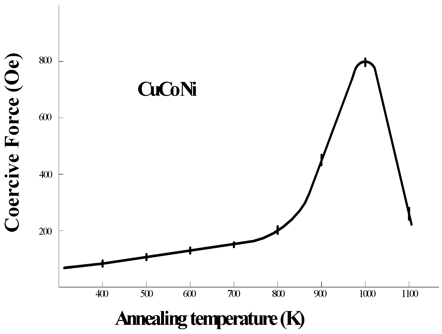
Figure 7.
Viscosity η (see (2)) as a function of temperature [6].
Figure 7.
Viscosity η (see (2)) as a function of temperature [6].

Figure 8.
Qualitative pattern of the change of residual stresses σr,z along the microwire radius. Curve α presents the initial state of these stresses in the metal strand and in the glass (in glass it is shown by black color and dashed line). In the metal strand these stresses are always tensile, i.e., positive [5,8]. The residual stresses in the silicate glass always compress the glass envelope (i.e., they are negative). Inside the region of plastic relaxation there is shown a section (near the strand center) where the applicability of the continuum model is violated. Curve β is a hypothetic form of residual stresses in the metal strand after removal of the glass envelope or disruption of its bound with the metal strand. As an example, there are presented the qualitative results of the calculation of residual stresses according to [10] (curve γ) which are different from our data.

Figure 9.
Permeability profile of a single layer, with a resonance frequency value of 0.67 GHz. (see [9]) The composition of microwires investigated here is Co68.15 Fe4.35 Si12.5B15 which has a very small saturation magnetostriction constant (λs) of 1.1 × 10⁻⁷.
Figure 9.
Permeability profile of a single layer, with a resonance frequency value of 0.67 GHz. (see [9]) The composition of microwires investigated here is Co68.15 Fe4.35 Si12.5B15 which has a very small saturation magnetostriction constant (λs) of 1.1 × 10⁻⁷.
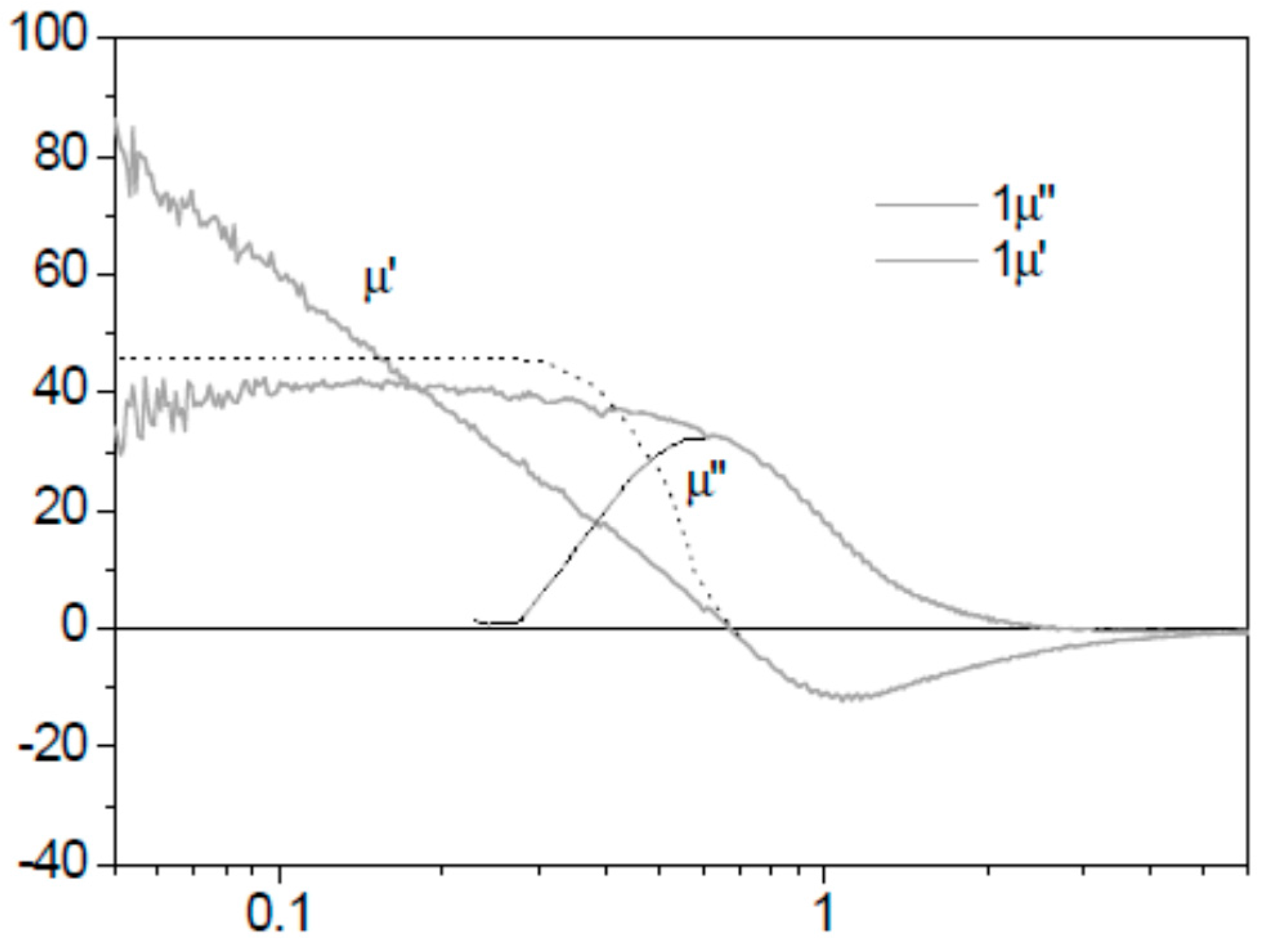
Figure 10.
Absorption characteristics of shielding by a microwire composite (Fe69C5B16Si10) in a high-frequency field in the range of frequencies 10–12 GHz (see [9]): initial state of the screen is then turned by (2) 90°, (3) 180°, and (4) 270° about the perpendicular axis shown in the figure.
Figure 10.
Absorption characteristics of shielding by a microwire composite (Fe69C5B16Si10) in a high-frequency field in the range of frequencies 10–12 GHz (see [9]): initial state of the screen is then turned by (2) 90°, (3) 180°, and (4) 270° about the perpendicular axis shown in the figure.

© 2017 by the authors. Licensee MDPI, Basel, Switzerland. This article is an open access article distributed under the terms and conditions of the Creative Commons Attribution (CC BY) license (http://creativecommons.org/licenses/by/4.0/).
Share and Cite
MDPI and ACS Style
Baranov, S.A.; Larin, V.S.; Torcunov, A.V. Technology, Preparation and Properties of the Cast Glass-Coated Magnetic Microwires. Crystals 2017, 7, 136. https://doi.org/10.3390/cryst7060136
AMA Style
Baranov SA, Larin VS, Torcunov AV. Technology, Preparation and Properties of the Cast Glass-Coated Magnetic Microwires. Crystals. 2017; 7(6):136. https://doi.org/10.3390/cryst7060136
Chicago/Turabian StyleBaranov, Serghei A., Vladimir S. Larin, and Alexander V. Torcunov. 2017. "Technology, Preparation and Properties of the Cast Glass-Coated Magnetic Microwires" Crystals 7, no. 6: 136. https://doi.org/10.3390/cryst7060136
Note that from the first issue of 2016, this journal uses article numbers instead of page numbers. See further details here.