
External-Voltage-Free Dielectrophoresis of Liquid Crystal Droplets
by
 ,
,
Sheng-Kuang Wu
1, 
Ting-Shan Mo
2,*,
Jia-De Lin
1,
Shuan-Yu Huang
3,4,
Hui-Chen Yeh
5,
Lin-Jer Chen
1 and
Chia-Rong Lee
1,* 1
Department of Photonics and Advanced Optoelectronics Technology Center, National Cheng Kung University, Tainan 701, Taiwan
2
Department of Electro-Optical Engineering, Kun Shan University of Technology, Tainan 710, Taiwan
3
Department of Optometry, Chung Shan Medical University, Taichung 402, Taiwan
4
Department of Ophthalmology, Chung Shan Medical University Hospital, Taichung 402, Taiwan
5
Graduate Institute of Electrical Engineering, National Kaohsiung First University of Science and Technology, Kaohsiung 824, Taiwan
*
Authors to whom correspondence should be addressed.
Crystals 2017, 7(7), 202; https://doi.org/10.3390/cryst7070202
Submission received: 12 May 2017
/
Revised: 26 June 2017
/
Accepted: 30 June 2017
/
Published: 3 July 2017
(This article belongs to the Special Issue Selected Papers from "3rd Asian Conference on Liquid Crystals, ACLC 2017")
Abstract
:This work reports, for the first time, a dielectrophoresis (DEP) effect-induced motion of liquid crystal (LC) droplets in an LC/monomer mixture sample with a poly-(N-vinyl carbazole) PVK-coated substrate without an external voltage. With the UV pre-irradiation of the PVK layer through a binary mask, a laterally non-uniform electric field can be induced between the pre-illuminated regions and the neighboring non-pre-illuminated PVK regions near the borders of the two regions. The phase separation occurs once the temperature is lower than 50 °C and the LC droplets can form in the sample. The pre-formed non-uniform field provides a DEP-like force to manipulate the small LC microdroplets in the pre-illuminated regions to effectively migrate to the adjacent non-pre-illuminated regions. The continuous supply of the LC from the pre-illuminated regions to the adjacent non-pre-illuminated regions significantly increases the diffraction efficiency of the grating sample. This study provides an insight into developing new external-voltage-free DEP-based devices that can be applied on various fields, such as photonics, displays, and biomedicines.
1. Introduction
Dielectrophoresis (DEP) is a phenomenon in which a dielectric particle is subjected to a force in a non-uniform electric field [1,2,3,4,5]. DEP was first understood and named by Herbert A. Pohl in the 1950s [6,7]. Particles need not be charged to exhibit DEP. In particular, all particles in the presence of an electric field can show DEP as long as the particles can be polarized. The DEP force exerted on a particle is dependent on the properties of the particle and its suspending medium, such as the dielectric property, shape, and size of the particle and the permittivity and conductivity of the suspending medium and the externally applied electric field [2,7]. The DEP force can be described as follows:
where R is the radius of the particle, εm is the permittivity of the suspending medium, and E0 is the magnitude of the applied electric field [2,6]. The factor K is known as the Clausius–Mossotti function, which depends on the complex permittivity of the particle and the medium and is a measure of the effective polarizability of the particle [4]. In the case of spherical particles, this factor is given by:
where εp is the permittivity of the particle [8]. If the particle moves in the direction of increasing electric field, then the behavior is referred to as positive DEP (K > 0). On the contrary, if the particle moves away from the high field region, then it is known as negative DEP (K < 0). This diversification provides a simple means for the separation of bio cells or the orientation and manipulation of nanoparticles and nanowires [2,6]. The increasing availability of micro-fabricated devices for silicon-based integrated systems has brought rapid advancement in a considerable amount DEP research and application since the late 1980s [9].
Liquid crystal (LC) has been widely used in many areas, especially in displays and photonics. The main attraction of LC is its externally controllable characteristics, for example, its optical properties can be modulated by applying electric, optical, or magnetic fields [10,11,12]. In addition to displays and photonic devices, basic works on LCs have drawn increasing attention recently, particularly the dynamically controllable movements of particles in LC media or LC droplets in dielectric media by use of DEP mechanisms [13,14,15]. Traditional DEP mechanisms to manipulate LC or non-LC particles require application of an external voltage. The current work reports for the first time a DEP-like effect that can induce the motion of LC droplets in a monomer matrix filled in a sample with a binary poly-(N-vinyl carbazole) (PVK)-coated substrate without the need of an external voltage. PVK is a polymeric photoconductor, and is widely used in organic devices as a hole transport layer [16]. PVK can also be integrated into LC devices as alignment film or patterned electrodes for developing configurable optical elements such as tunable spatial filter, Fresnel lens, and lasers [17,18,19]. In the present investigation, the binary PVK pattern can be obtained by pre-irradiating one UV light on the PVK-coated substrate via a binary photomask. A laterally non-uniform electric field can be pre-built between the pre-illuminated regions and the adjacent non-pre-illuminated PVK regions near the borders of the two regions. Following cooling of the sample below 50 °C, the LC droplets can form, and the non-uniform field may induce a DEP-like force. This force can drive the small LC microdroplets in the pre-illuminated regions to effectively move to the adjacent non-pre-illuminated regions, thereby significantly increasing the diffraction efficiency of the grating. The present DEP-like mechanism provides a new approach to simply controlling the movement of LC droplets with sizes ranging from micron to nanometer without the need of an external voltage.
2. Sample Preparation and Experimental Setup
The chemical structures of the materials used in this study are shown in Figure 1. The LC used (Figure 1a) is TL205 (no = 1.5309, ne = 1.74 at 589 nm and 25 °C, clearing point: TC ≈ 85 °C), purchased from Merck. The photoconductive polymer (Figure 1b) used is PVK, purchased from Sigma–Aldrich. A solution of chlorobenzene solvent with PVK at a weight ratio of 98:2 is prepared and spin-coated onto an indium–tin–oxide (ITO)-coated glass slide at two steps with 2000 rpm for 30 s and 500 rpm for 10 s. The coated substrate is then pre-baked in an oven at 80 °C for 20 min and post-baked at 120 °C for 60 min after the pre-bake. A binary photomask is used in this work; it has transparent and opaque stripes with equal widths of 150 μm. The photomask is custom-made by etching a chromium oxide layer using electron-beam lithography. The binary PVK layer with alternatively pre-illuminated and non-pre-illuminated stripes on the ITO slide can be obtained after the irradiation of a non-polarized UV light with an intensity of 9.2 mW/cm2 from a 7.5 W Hg lamp through binary photomask for 48 h. Thereafter, another ITO substrate without any alignment film and treatment is combined with the binary PVK-coated one to fabricate the empty cell with a cell gap of 12 μm. TL205 and monomer [Norland Optical Adhesive 63 (NOA63)] at a weight ratio of 35:65 cannot dissolve with each other; thus, the phase separation between them occurs when the temperature is lower than 50 °C. Once the temperature is equal to or higher than 50 °C, the LC in the mixture becomes isotropic. Accordingly, the materials can instead uniformly mix after appropriate stirring. The uniform mixture is then transferred into an empty cell, which is prefixed at a hot stage at 50 °C. The edges of the sample are sealed with epoxy, and then the sample undergoes a cooling process to room temperature (TR ≅ 25 °C) at a rate of 5 °C/min in 5 mins. The image of the sample is observed and recorded in two steps: the cooling step from 50 °C to TR for 5 min and then the constant-TR step for 16 h under the polarizing optical microscope (POM) with crossed polarizers (IX-71, Olympus, Taichung city, Taiwan). A long-pass filter is used to filter out the illumination with a wavelength shorter than 500 nm from light source of POM to prevent the radical polymerization of NOA63. Notably, no external voltage bias is applied on the sample in this study.
3. Results and Discussion
3.1. Formation of LC Droplets with Significantly Different Sizes between the Pre-Illuminated and Non-Pre-Illuminated Regions in the Grating Sample at the Cooling Step
The dynamic variation in the formation of LC droplets in the LC/monomer mixture sample with the binary PVK layer under the POM with crossed polarizers is displayed in Video S1 (in the Supplementary File), in which the displayed speed is accelerated eight-fold at the cooling step. Figure 2a–e shows the selected images of the sample in Video S1 at cooling time tC = 0, 30, 60, 150, 300 s. Figure 2f shows the photomask pattern under the POM (with no analyzer), in which the bright and dark regions of the pattern correspond to the pre-illuminated and non-pre-illuminated regions in the grating sample, respectively. The experimental results show that the small LC droplets can form simultaneously in the pre-illuminated and non-pre-illuminated regions of the grating sample via the phase separation of the monomer and LC once the temperature is lower than 50 °C. In the non-pre-illuminated regions, the LC droplets quickly become large at the cooling step through the random coalescence among neighboring droplets; these droplets randomly move due to the strong thermal fluctuation. On the contrary, the small LC droplets in the pre-illuminated regions expand slightly; as a result, the droplets nearly sustain their very small sizes (approximately a few micrometers) at the entire cooling step. Thus, the discrepancy between the average sizes of the LC droplets in the two regions at TR become very large (Figure 2e). Consequently, a grating with alternative distribution of small and large droplets forms, and the grating has a first-order diffraction efficiency of nearly 4.7% (Figure 3) at the end of the cooling step.
To acquire additional information about the origin of such a result, the motions of the small and large droplets in the pre-illuminated and non-pre-illuminated regions are surveyed, as well as their relation in Video S2 (in the Supplementary File) which is a film produced via local magnification in Video S1. Clearly, the small LC droplets in the pre-illuminated regions continually migrate to and accumulate in the non-pre-illuminated regions near the borders between the two regions. At the same time, the large LC droplets in the non-pre-illuminated regions continually enlarge via random coalesce with adjacent small droplets; these droplets are generated by those accumulated droplets originally located in the non-pre-illuminated regions near the borders of the two regions. From the observed result, the key factor for inducing the binary distribution of large and small LC droplets at the cooling step must be associated with a specific force that induces the small microdroplets in the pre-illuminated regions to continually migrate to the non-illuminated regions near the borders of the two regions. To determine the origin of the force, the motion of the LC droplets formed in the monomer matrix of the grating sample is further observed and recorded at the constant-TR step for a long period (16 h). Associated experimental results are shown below.
3.2. Phenomenon of Migration of Small LC Microdroplets from the Pre-Illuminated Regions to the Non-Pre-Illuminated Regions of the Grating Sample at the Constant-TR Step
After the sample undergoes the cooling step from 50 °C to TR, the image of the grating sample is further observed and recorded at the constant-TR step for 16 h under the POM with crossed polarizers. The time-lapse photograph for observing the variation in the grating sample image at TR for 16 h is displayed in Video S3 (in the Supplementary File). Figure 3a–h show the observed images of the grating sample at TR selected at observation time tR = 0, 1, 2, 4, 7, 10, 13, and 16 h in order. Apparently, the large droplets in the non-pre-illuminated regions exhibit less motion, and the migration of the small droplets in the pre-illuminated regions to the non-pre-illuminated regions near the borders of the two regions becomes slow at the constant-TR step. The reason is that the viscosity of the monomer matrix becomes low at TR. The migration of the small droplets is slow but apparently lasts for a long duration of approximately 10 h from tR = 0 to tR = 10 h. After tR = 10 h, the migration of the small droplets nearly ceases. The corresponding first-order diffracted dynamics for the grating during the migration of the small droplets is recorded from tR = 0 to tR = 16 h using a He-Ne laser beam with a wavelength of 633 nm to probe the grating. The result is plotted in Figure 4, which shows that the grating efficiency increases quickly from 4.7 % at tR = 0 to 7.9% at tR = 4 h and slowly from 7.9% at tR = 4 h to 8.6% at tR = 10 h. After tR = 10 h, the efficiency saturates to a constant value. This result is consistent with the migration dynamics of the small droplets from the pre-illuminated regions to the adjacent non-pre-illuminated regions near the borders of the two regions (Figure 3a–h).
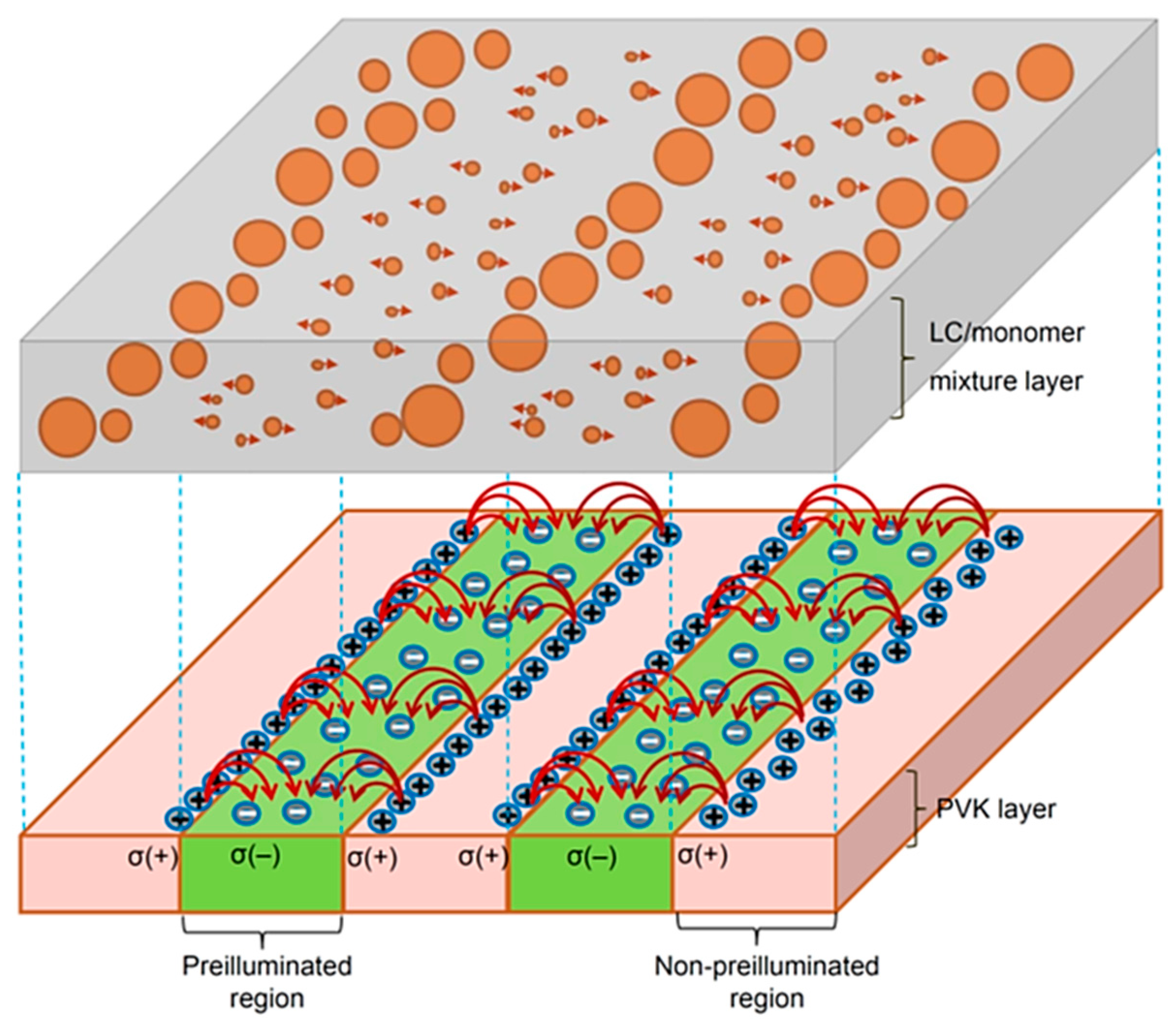
The above-mentioned experimental results displayed in Figure 3 present a DEP-like phenomenon. As a result, the small droplets present a uni-directional migration by the DEP force from the pre-illuminated regions to the adjacent non-pre-illuminated regions near the borders of the two regions. To the best of our knowledge, this work is the first discovery of such an unusual DEP effect without the need for an external voltage. The above-mentioned results, and the fact that the LC droplets are electrically neutral, show that a laterally non-uniform electric field with an increasing strength from the pre-illuminated regions to the adjacent non-pre-illuminated regions near the borders between the two regions must be developed after the UV pre-exposure on the PVK layer through the binary photomask. To explain the DEP-like phenomenon at constant-TR step emerging in Figure 3, a model as displayed in Figure 5 is addressed by the enlightenment of the photorefractive (PR) effect described in detail in the reviewed literature, as PVK is known to be a popular PR polymer [20]. To clearly illustrate the model, a figure that separates the interior of the grating sample into LC-droplets/monomer and PVK layers is shown in Figure 5, in which the two layers are connected in reality in the sample. Electron–hole pairs can generally be created in the pre-illuminated regions, but less so in the non-pre-illuminated regions of the PVK layer under the UV pre-irradiation through the binary photomask. The holes are the mobile charge carriers after the UV irradiation on the PVK [20]. The generation of the photocharges mainly occurs on the exposed surface in the pre-illuminated regions of the PVK because the absorption of PVK in the UV band is strong [21]. The mobile holes in the pre-illuminated regions diffuse toward the non-pre-illuminated regions as a result of its inhomogeneous concentration after the non-uniform UV illumination (in the present case, no drift for holes can occur because no external voltage is applied on the sample). When these holes diffuse toward the non-pre-illuminated regions, part of them will be trapped by the defects. The trap of the holes mainly occurs in the non-pre-illuminated region near the borders between the two regions, because the mobile holes present low probability to further diffuse into the deeper, non-conductive non-pre-illuminated regions. The net charge left in the pre-illuminated regions then becomes negative. The trap of these holes in the non-illuminated regions is limited on the borders between the two regions; thus, compared with the broad distribution of the net negative charges in the entire pre-illuminated regions, the positive surface charge density in the non-pre-illuminated regions near the borders [σ(+)] is higher than the negative one in the pre-illuminated regions [σ(‒)]; this phenomenon induces a non-uniform internal electric field with a strength gradient increasing from the pre-illuminated regions to the non-pre-illuminated regions near the borders in the sample (Figure 5). The non-uniform internal electric field exhibits a gradient from the pre-illuminated to the adjacent non-pre-illuminated regions, and the dielectric constant of the LC droplet (εp/ε0 ≅ ε||/ε0 = 9.1 at 1 kHz) is larger than that of the monomer (εm/ε0 = 3.2 at 1 kHz). Thus, the small LC droplets in the pre-illuminated regions bear a DEP force toward the adjacent non-pre-illuminated regions according to Equations (1) and (2). These small droplets can continually move toward, and then accumulate and merge with, one another in the non-pre-illuminated regions near the borders of the two regions (Figure 3a–h or Video S3).
3.3. Further Discussion about the Key Role of the Discovered Non-Uniform Internal Field Playing at the Cooling Step
In this section, the key role of the discovered non-uniform internal field playing at the cooling step is discussed. As explained by the above-mentioned model, the non-uniform electric field has been pre-built after the UV pre-exposure on the PVK layer through the binary photomask. The small microdroplets in the pre-illuminated regions of the sample should be driven by the DEP force, owing to the non-uniform internal field once the phase separation occurs at the beginning of the cooling step. This claim has been proven previously by the dynamic display in Video S2. When the small droplets approach the non-illuminated regions near the borders, they can accumulate and merge with one another to become large droplets. In the initial stage of the generation of the LC droplets, this uni-directional migration is very animated, because of the low viscosity of the monomer matrix at high temperature. At the same time, the random coalescence of the LC droplets in the non-pre-illuminated regions is also active, because of the strong thermal fluctuation at high temperatures. The strong thermal fluctuation can activate the accumulated LC droplets at the borders originally from the pre-illuminated regions; thus, these droplets can escape from the confinement of the internal field and then randomly move to the deeper field-free regions of the non-pre-illumination. In these regions, they have a high probability of meeting and merging into large droplets. However, as the temperature gradually decreases to TR, the viscosity of the monomer matrix increases. Consequently, the motion of the LC droplets in the two regions becomes much inactive, as shown in Video S3. In other words, the analysis shows that the non-uniform internal electric field plays a key role in effectively inducing the continuous output of the LC from the pre-illuminated regions and the continuous input of LC into the non-pre-illuminated regions. This fact successively limits and enhances the enlargement of the droplets in the pre-illuminated and non-pre-illuminated regions, respectively, at the cooling process. Therefore, the final distribution of the LC droplets with a significant difference between the average droplet sizes in the two regions of the grating can be obtained at TR.
4. Conclusions
In this study, the dynamic variation in the formation of the LC-droplet/monomer grating with a PVK pattern is investigated. The PVK pattern is pre-obtained after the exposure of one UV light through a binary photomask. The experimental results show that an internal electric field can be induced between the pre-illuminated regions and the adjacent non-pre-illuminated regions near the borders of the two regions, thereby possibly producing a DEP-like force that effectively migrates LC microdroplets from pre-illuminated regions to non-pre-illuminated regions. To the best of our knowledge, this work is the first to demonstrate the DEP phenomenon without the need for applying a bias voltage. The continuous supply of the LC from the pre-illuminated regions to the adjacent non-pre-illuminated regions significantly increases the diffraction efficiency of the grating sample. The external-voltage-free DEP mechanism provides a new approach to control micro- to nano-scaled particles in various applications, such as photonics, displays, and biomedicine.
Supplementary Materials
The following are available online at www.mdpi.com/2073-4352/7/7/202/s1, Video S1: Dynamic formation of LC droplets in the pre-illuminated and non-pre-illuminated regions in the grating sample at the cooling step; Video S2: Local magnification of Video S1; Video S3: Dynamics of migration of small LC microdroplets from the pre-illuminated regions to the non-pre-illuminated regions of the grating sample at the constant-TR step.
Acknowledgments
The authors would like to thank the Ministry of Science and Technology of Taiwan (Contract numbers: MOST 103-2112-M-006-012-MY3 and MOST 104-2628-E-006-015-MY2) and the Advanced Optoelectronic Technology Center, National Cheng Kung University, under the Top University Project from the Ministry of Education, for financially supporting this research.
Author Contributions
Sheng-Kuang Wu and Ting-Shan Mo conceived and designed the experiments; Sheng-Kuang Wu performed the experiments; Jia-De Lin, Lin-Jer Chen, and Chia-Rong Lee analyzed the data through detailed discussion; Shuan-Yu Huang and Hui-Chen Yeh contributed reagents/materials/analysis tools; Chia-Rong Lee wrote the paper.
Conflicts of Interest
The authors declare no conflict of interest. The founding sponsors had no role in the design of the study; in the collection, analyses, or interpretation of data; in the writing of the manuscript, or in the decision to publish the results.
References
- Pohl, H.A. Dielectrophoresis: The Behaviorof Neutral Matter in Nonuniform Electric Fields; Cambridge University Press: Cambridge, UK, 1978; Volume 80. [Google Scholar]
- Morgan, H.; Green, N.G. AC Electrokinetics: Colloids and Nanoparticles, 2nd ed.; Research Studies Press Ltd.: Baldock, UK, 2003. [Google Scholar]
- Hughes, M.P. Nanoelectromechanics in Engineering and Biology; CRC Press: Boca Raton, FL, USA, 2002. [Google Scholar]
- Jones, T.B. Electromechanics of Particles; Cambridge University Press: New York, NY, USA, 1995. [Google Scholar]
- Kirby, B.J. Micro- and Nanoscale Fluid Mechanics: Transport in Microfluidic Devices; Cambridge University Press: New York, NY, USA, 2010. [Google Scholar]
- Pohl, H.A. The Motion and Precipitation of Suspensoids in Divergent Electric Fields. J. Appl. Phys. 1951, 22, 869–871. [Google Scholar] [CrossRef]
- Pohl, H.A. Some effects of nonuniform fields on dielectrics. J. Appl. Phys. 1958, 29, 1182–1188. [Google Scholar] [CrossRef]
- Irimajiri, A.; Hanai, T.; Inouye, A. A dielectric theory of “multi-stratified shell” model with its application to a lymphoma cell. J. Theor. Biol. 1979, 78, 251–269. [Google Scholar] [CrossRef]
- Lapizco-Encinas, B.H.; Rito-Palomares, M. Dielectrophoresis for the manipulation of nanobioparticles. Electrophoresis 2007, 28, 4521–4538. [Google Scholar] [CrossRef] [PubMed]
- Lee, S.H.; Lee, S.L.; Kim, H.Y. Electro-optic characteristics and switching principle of a nematic liquid crystal cell controlled by fringe-field switching. Appl. Phys. Lett. 1998, 73, 2881–2883. [Google Scholar] [CrossRef]
- Park, J.W.; Ahn, Y.J.; Jung, J.H.; Lee, S.H.; Lu, R.; Kim, H.Y.; Wu, S.T. Liquid crystal display using combined fringe and in-plane electric fields. Appl. Phys. Lett. 2008, 93, 081103–081105. [Google Scholar] [CrossRef]
- Wang, M.; He, L.; Zorba, S.; Yin, Y. Magnetically Actuated Liquid Crystals. Nano Lett. 2014, 14, 3966–3971. [Google Scholar] [CrossRef] [PubMed]
- Kim, Y.; Francl, J.; Taheri, B.; West, J.L. A method for the formation of polymer walls in liquid crystal/polymer mixtures. Appl. Phys. Lett. 1998, 72, 2253. [Google Scholar] [CrossRef]
- Gheorghiu, N.; West, J.L.; Glushchenko, A.V.; Mitrokhin, M. Patterned field induced polymer walls for smectic A bistable flexible displays. Appl. Phys. Lett. 2006, 88, 263511:1–263511:3. [Google Scholar] [CrossRef]
- Ren, H.; Wu, S.T.; Lin, Y.H. In situ observation of fringing-field-induced phase separation in a liquid-crystal monomer mixture. Phys. Rev. Lett. 2008, 100, 117801. [Google Scholar] [CrossRef] [PubMed]
- Penwell, R.C.; Ganguly, B.N.; Smith, T.W. Poly(N-vinylcarbazole): A selective review of its polymerization, structure, properties, and electrical characteristics. J. Polym. Sci. Macromol. Rev. 1978, 13, 63–160. [Google Scholar] [CrossRef]
- Lo, K.C.; Wang, J.D.; Lee, C.R.; Mo, T.S. Electrically controllable and polarization-independent Fresnel zone plate in a circularly symmetric hybrid-aligned liquid crystal film with a photoconductive polymer layer. Appl. Phys. Lett. 2007, 91, 181104. [Google Scholar] [CrossRef]
- Huang, C.Y.; Ma, J.M.; Mo, T.S.; Lo, K.C.; Lo, K.Y.; Lee, C.R. All-optical and polarization-independent spatial filter based on a vertically-aligned polymer-stabilized liquid crystal film with a photoconductive layer. Opt. Express 2009, 17, 22386–22392. [Google Scholar] [CrossRef] [PubMed]
- Lee, C.R.; Huang, S.C.; Lin, S.H.; Lin, Z.Y.; Huang, S.Y.; Mo, T.S. Distributed feedback laser with optoelectronic tunability in dye-doped cholesteric liquid crystal with coated photoconductive layer. Appl. Phys. B 2011, 105, 689–695. [Google Scholar] [CrossRef]
- Moerner, W.E.; Grunnet-Jepsen, A.; Thompson, C.L. Photorefractive polymers. Annu. Rev. Mater. Sci. 1997, 27, 585–623. [Google Scholar] [CrossRef]
- Wang, Y. Photoconductivity of fullerene-doped polymers. Nature 1992, 356, 585–587. [Google Scholar] [CrossRef]
Figure 1.
Chemical structures of materials used in the present work: (a) LCs (TL205) and (b) photoconductive polymer (PVK).
Figure 1.
Chemical structures of materials used in the present work: (a) LCs (TL205) and (b) photoconductive polymer (PVK).
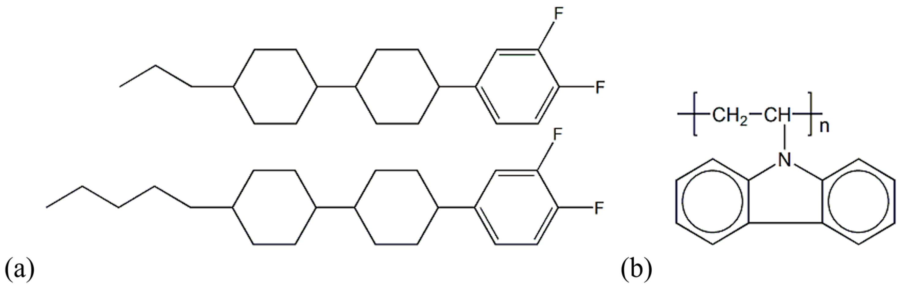
Figure 2.
Images of the LC/monomer mixture sample with binary PVK layer at the cooling step from 50 °C to TR in 5 mins at a rate of 5 °C/min observed under the POM with crossed polarizers at cooling time tC = (a) 0 s, (b) 30 s, (c) 60 s, (d) 150 s, and (e) 300 s. (f) The binary photomask pattern observed under the POM (with no analyzer) is displayed for reference to identify the pre-illuminated and non-pre-illuminated regions of the UV light on the PVK layer. The area inside the rectangular dotted frame of this pattern corresponds to the zone of the recorded images shown in (a–e).

Figure 3.
Image of the grating sample with binary PVK layer recorded at the constant-TR step under the POM with crossed polarizers at observation time tR = (a) 0 h, (b) 1 h, (c) 2 h, (d) 4 h, (e) 7 h, (f) 10 h, (g) 13 h, and (h) 16 h.
Figure 3.
Image of the grating sample with binary PVK layer recorded at the constant-TR step under the POM with crossed polarizers at observation time tR = (a) 0 h, (b) 1 h, (c) 2 h, (d) 4 h, (e) 7 h, (f) 10 h, (g) 13 h, and (h) 16 h.
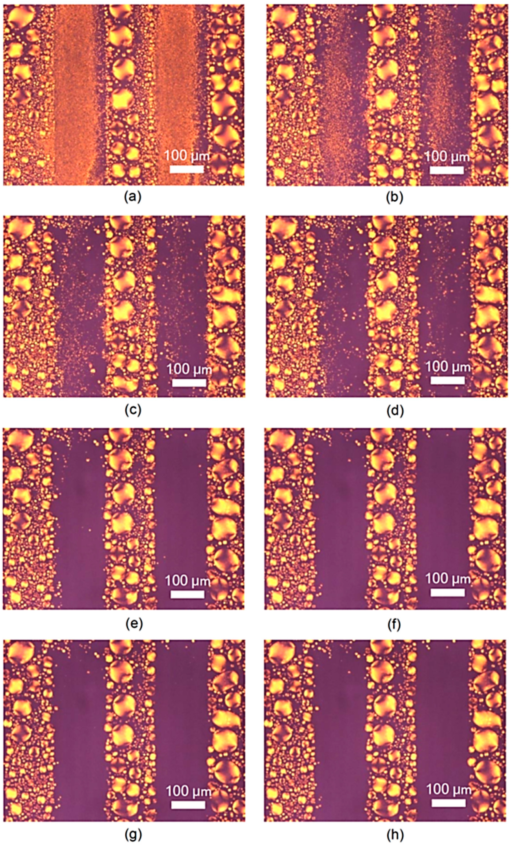
Figure 4.
Dynamic variation in the measured diffraction efficiency of the LC/monomer grating sample with the observation time at TR.
Figure 4.
Dynamic variation in the measured diffraction efficiency of the LC/monomer grating sample with the observation time at TR.
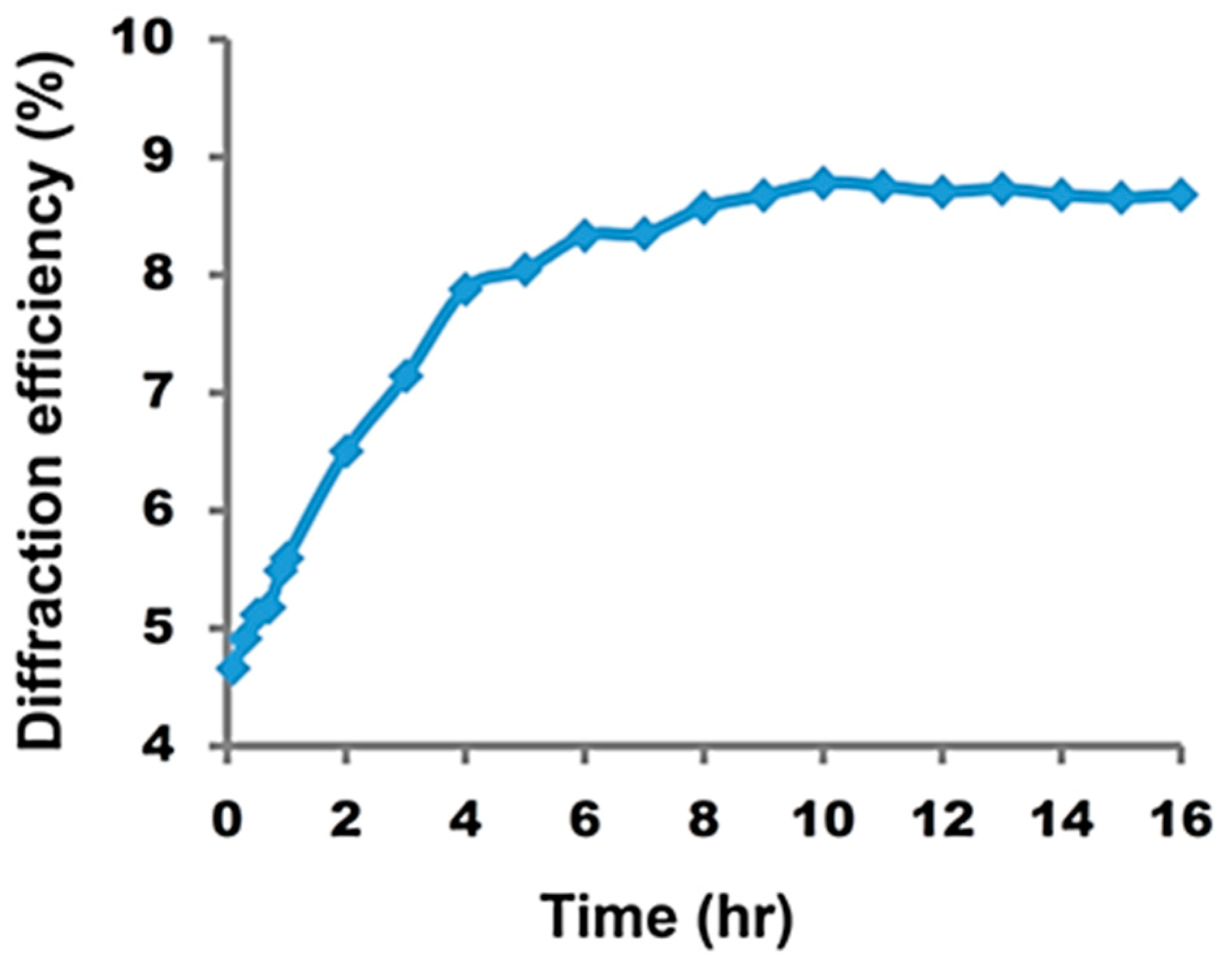
Figure 5.
Model to explain the DEP-like phenomenon at constant-TR step. The non-uniform internal electric field has an increasing strength gradient from the pre-illuminated regions to the adjacent non-pre-illuminated regions near the borders of the two regions (the lower half part). The small LC droplets in the pre-illuminated regions uni-directionally migrate toward the adjacent non-pre-illuminated regions near the borders.
© 2017 by the authors. Licensee MDPI, Basel, Switzerland. This article is an open access article distributed under the terms and conditions of the Creative Commons Attribution (CC BY) license (http://creativecommons.org/licenses/by/4.0/).
Share and Cite
MDPI and ACS Style
Wu, S.-K.; Mo, T.-S.; Lin, J.-D.; Huang, S.-Y.; Yeh, H.-C.; Chen, L.-J.; Lee, C.-R. External-Voltage-Free Dielectrophoresis of Liquid Crystal Droplets. Crystals 2017, 7, 202. https://doi.org/10.3390/cryst7070202
AMA Style
Wu S-K, Mo T-S, Lin J-D, Huang S-Y, Yeh H-C, Chen L-J, Lee C-R. External-Voltage-Free Dielectrophoresis of Liquid Crystal Droplets. Crystals. 2017; 7(7):202. https://doi.org/10.3390/cryst7070202
Chicago/Turabian StyleWu, Sheng-Kuang, Ting-Shan Mo, Jia-De Lin, Shuan-Yu Huang, Hui-Chen Yeh, Lin-Jer Chen, and Chia-Rong Lee. 2017. "External-Voltage-Free Dielectrophoresis of Liquid Crystal Droplets" Crystals 7, no. 7: 202. https://doi.org/10.3390/cryst7070202
Note that from the first issue of 2016, this journal uses article numbers instead of page numbers. See further details here.