
An Electrically Tunable Liquid Crystal Lens with Coaxial Bi-Focus and Single Focus Switching Modes


Department of Photonics, National Cheng Kung University, Tainan 701, Taiwan
*
Author to whom correspondence should be addressed.
Crystals 2017, 7(7), 209; https://doi.org/10.3390/cryst7070209
Submission received: 30 May 2017
/
Revised: 3 July 2017
/
Accepted: 4 July 2017
/
Published: 7 July 2017
(This article belongs to the Special Issue Selected Papers from "3rd Asian Conference on Liquid Crystals, ACLC 2017")
Abstract
:A hole-patterned electrode liquid crystal (LC) lens with electrically switching coaxial bi-focus and single focus modes of tuning is demonstrated. The proposed LC lens mainly consists of a two LC layer (TLCL) structure with different thicknesses to achieve higher focusing power than the conventional hole-patterned electrode LC lens with the same aperture size. In the TLCL structure, one LC layer, doped with 3 wt % RM257, was photopolymerized to achieve a fixed focusing power of 18.5 Diopter. Due to polarization dependence in TLCL lenses, an additional 90° twisted nematic (TN) cell was used to change the incident polarization in order to switch lens functions on or off. As a result, a fixed focusing power of 18.5 Diopter was achieved when voltages of 10 Vrms were applied to the 90° TN cell. In addition, the switching capabilities of the bi-focus and single focus modes were achieved when operating individually with applied voltages from 20 Vrms to 90 Vrms, and higher voltages of over 90 Vrms, respectively. The maximum focusing power in the fabricated TLCL lens is 30.9 Diopter.
1. Introduction
Owing to the key characteristics of optical birefringence and dielectric anisotropy, liquid crystals (LCs) are usually used to fabricate numerous electro-optical devices such as tunable LC lenses, displays, phase modulators, and optical gratings, among others [1,2,3,4]. Particularly, studies on tunable LC lenses have gained much attention recently given their suitability for several emerging applications, such as 3D display techniques, wearable displays, and augmented reality (AR). The operation principle of tunable LC lenses is mostly electrically driven in order to reorient LC molecules to achieve ideal gradient refractive index distributions, so that incident light passing through them modifies its wave front to focus or defocus. Until now, numerous types of LC lenses have been developed, such as the diffractive LC lens [5,6], LC lenses with a curved electrode or a multi-ring electrode [7,8,9], smectic LC lenses [10], cholesteric LC lenses [11], and circular hole-patterned LC lenses [12,13,14]. Among these types of LC lens, the hole-patterned electrode LC lens possesses the features of tunable focus, a wide lens aperture size range, and easy fabrication. Therefore, the hole-patterned electrode LC lens has been widely investigated and developed in numerous fields including imaging systems [15,16,17], 3D displays [18,19,20], and biological applications [21,22]. However, numerous issues also exist and must be resolved for this type of LC lens. For example, the disclination line is a common issue, owing to discontinuous LC orientation induced by the fringe electric field [23]. Several approaches have been implemented to prevent this issue including polymer-stabilized LCs on substrate surfaces [24], applying an additional electric field in cells [25,26], and adding an insulator layer between the LC layer and the electrode in cells [12,27].
Generally, LC lenses with large phase retardation in the radial directions are considered high-focusing power lenses and are very beneficial for practical applications, such as head-mounted displays and integral image systems [28,29]. When combined with glass lenses, a larger range of focusing power is available to achieve shorter focal lengths, but larger spaces are also needed [30,31,32]. Previously, Lin et al. used a built-in polymer–LC composed film to effectively achieve shorter focal length [33], but maintaining the ideal uniformity of polymer–LC composed films is a challenging fabrication process. In the present study, we demonstrate that a hole-patterned electrode LC lens is capable of electrically tuning focuses and switching between single and bi-focal modes. Particularly, higher focusing power in the single focal mode is available for this proposed LC lens compared with the conventional hole-patterned electrode with the same aperture size. The proposed LC lens is mainly composed of two LC layers (TLCL) sandwiched by three conductive indium tin oxide (ITO) glass substrates, the middle layer of which has a hole-patterned ITO electrode. After determining the suitable thickness of the two LC layers, this TLCL LC lens is characterized by a free disclination line and high focusing power.
2. Simulation Design and Fabrication of the Proposed LC Lens
2.1. Simulation Design
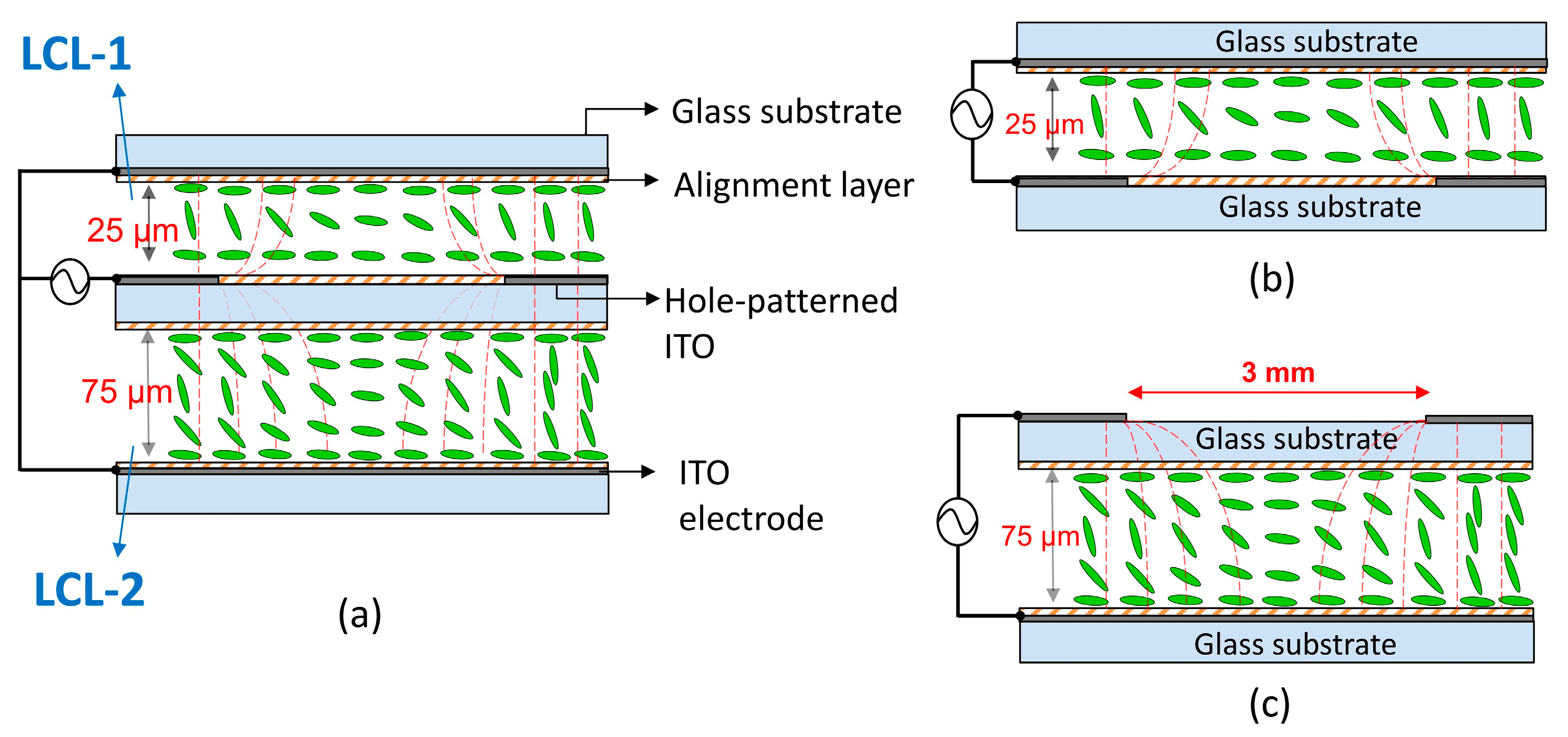
Figure 1a depicts the schematic cross-section of the proposed LC lens with electrical operation. The TLCL structure comprised a layer with a thickness of 25 μm (named LCL-1) and another with a thickness of 75 μm (named LCL-2). During electrical operation, an AC voltage with a 1 kHz square waveform is applied to the conductive glass substrates, one terminal of which is connected to the hole-patterned electrode on the top surface of the middle glass substrate, while another terminal is simultaneously connected to both ITO electrodes on the top and bottom glass substrates. For simulation and comparison, the proposed LC lens with a TLCL structure can be decomposed and segmented into two major parts, as shown in Figure 1b,c. Figure 1c depicts the conventional similarities of a hole-pattern electrode LC lens with a 75 μm thickness of LC layer, on which a 1.1 mm-thick glass substrate is used as an insulator layer in order for non-uniform electric fields to penetrate the central electrode [12], and the achievement of smooth fringe-electric field distribution in the LC layer in order to prevent the occurrence of a disclination line [27]. Figure 1b shows the other conventional similarities between a hole-pattern electrode LC lens with a 25 μm-thick LC layer and another without an insulator layer. In this study, we simulated and compared the characteristics of the TLCL lenses with individual hole-patterned electrode LC lenses, as shown in Figure 1b and c. Using the commercial software LCD master (Shintech, Yamagushi, Japan), we simulated and analyzed the distribution of equipotential lines and LC molecular orientation in order to verify and compare the characteristics of TLCL LC lenses in experiments. The simulation conditions of the TLCL structure are as follows: glass dielectric constant, 7.6; thickness of the ITO conductive film, 100 nm; thickness of the LC alignment layer with strong anchoring force, 200 nm; and LC pretilt angle, 3°. The director model was used for the simulation studies. In addition, the E7 LCs possess the following physical parameters: elastic constants (K11 = 12 pN, K22 = 6.5 pN, and K33 = 19.5 pN); optical birefringence (Δn), 0.221; dielectric anisotropy (Δε), 14.1; and rotational viscosity (γ1), 39 mPas.
2.2. LC Lens Fabrication
The major fabrication processes of the TLCL lenses are shown in Figure 2. The thickness of the ITO glass substrates (Chipset Technology, Miaoli, Taiwan) is 1.1 mm. In Figure 1a, the middle ITO conductive glass substrate was processed with normal photolithography to generate a circular hole-pattern with a diameter of 3 mm. Then, the photocurable monomer of NOA65 (n = 1.524, Norland Products, Cranbury, NJ, USA) was deposited via a spinning coater on the hole-patterned ITO electrode of about 15 μm film thickness, and exposed to a UV light (λ = 365 nm, Mightex, Pleasanton, CA, USA) with a power intensity of 20 mW/cm2 for 2 min. The completely exposed NOA65 film functions as an insulation layer that slightly modulates the distribution of the electric equipotential lines in cells. Finally, the middle glass substrate was processed with dip coating in a solution of polyvinyl alcohol (PVA, Sigma-Aldrich, St. Louis, MO, USA) and mechanically rubbed to achieve homogeneous LC alignments. Both the top and bottom glass substrates were coated with homogeneous polyimide (PI, SE-7492, Nisson Chemical, Tokyo, Japan) on their ITO electrodes via spin coating and mechanically rubbed. Figure 2a shows the orderly stacking of the three finished glass substrates with suitable Mylar spacers, which schematically shows a completed TLCL lens before filling LCs. Two LC layers with a thickness of 25 μm and 75 μm were controlled by Mylar spacers. The capillarity effect was employed to fill the 75 μm empty gap with a LC mixture composed of the following ingredients: 96.5 wt % nematic LCs (E7, Daily Polymer, Kaohsiung, Taiwan), 3 wt % reactive mesogen (RM257, HCCH, Yangzhong, China), and 0.5 wt % photo-initiator (Irgacure-651, TCI Chemical, Tokyo, Japan). The RM257, which possesses the LC building block structure, was photopolymerized to form polymer networks to provide constraints on the LC molecules. Simultaneously, a voltage of 40 Vrms was applied to the TLCL lens and exposed to UV light with a power intensity of 30 mW/cm2 for 30 min, as shown in Figure 2b. The choice of applied voltages during UV exposure was based on the available shortest focal length of the LC lens during electrical operation. After the UV exposure processes, the low-RM257 polymer networks that existed in LCL-2 will fix the LC molecular orientation, as shown in Figure 2c. Similarly, the empty 25 μm gap was filled with E7 LCs without more processes to complete the TLCL lens. The two homogeneous LC layers had parallel rubbing directions.
2.3. Electric Operation Versus Switching Focal Modes in Proposed LC Lenses
With the exception of the main part of the TLCL lens itself, adding a 90° twisted nematic (TN) LC cell during electric operation achieves the on or off lens function. The electrical operation of the TLCL lens is schematically depicted in Figure 3. Figure 3a shows the TLCL lens in the off state. An incident light with p-polarization is passed through the 90° TN cell in the off state to change p-polarization into s-polarization, which further enters the TLCL lens in order that its wave front not to be modulated, given that there is no spatial phase retardation. For the TLCL lens in the on state, the TLCL lens and the TN cell were simultaneously connected by an amplified AC electrical signal with a 1 kHz square waveform via a function generator (33220A, Agilent, Santa Clara, CA, USA) and an amplifier (F10A, FLC Electronics, Partille, Sweden), as shown in Figure 3b,c. The red and black lines denote the electrical connecting lines from the beginning of the two terminals of the electrical amplifier. The red line shares electrical signals with the top electrode of the TN cell and the hole-patterned electrode of the middle substrate of the TLCL lens. Similarly, the black line shares electrical signals with the bottom electrode of the TN cell and the electrodes of the top and bottom substrates of the TLCL lens. As shown in Figure 3b, the TLCL lens is operated in a coaxial bi-focus mode via electrical operation, with various voltages V1 over the threshold voltage of the TN cell. An incident light beam with p-polarization passing through the TN cell in its on state will maintain its p-polarization, and then enter the TLCL lens through the LCL-1 and LCL-2 layers. When lower voltages of V1 in the range of 20–90 Vrms are applied, an interference of the concentric circular patterns was observed in the LCL-1 layer, in areas close to the boundaries of the lens aperture and not in the central areas, thus the tunable coaxial bi-focal modes are available when combined with the fixed interference of the concentric circular patterns that were observed in the LCL-2 layer. When applying higher voltages of V2 over 90 Vrms, the completed interference patterns fully distribute across the whole lens aperture in the LCL-1 layer. Therefore, higher focusing power with shorter focal length is achieved with the abovementioned lens combinations. To identify the focal length of the LC lens, a collimated and expanded He-Ne laser beam (λ = 632.8 nm) was passed through an LC lens that operated at focused status. A charge-coupled device (CCD) camera was used to observe the focal point at which the maximum intensity distribution can be recorded. The focal length defined the distance between the LC lens and the focal point. We observed two focal points at different positions while the TLCL LC lens operated in the coaxial bi-focus mode.
3. Experimental Results
3.1. Comparisons Between the TLCL Lenses and Conventional LC Lenses
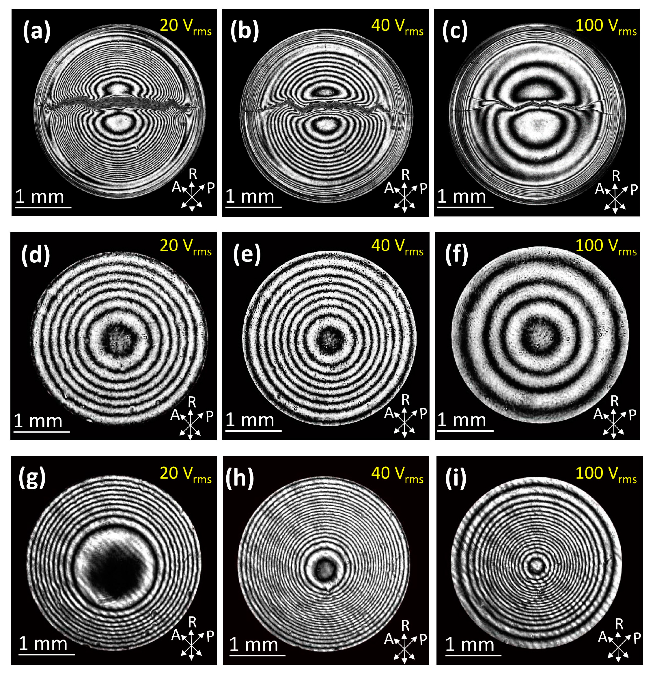
To identify the radial distribution of the phase retardation of the hole-patterned electrode LC lenses, an experimental setup with a collimated and expanded He-Ne laser beam (λ = 632.8 nm) was used. This experiment measured and recorded the interference patterns that occurred in the LC lenses [24]. The completed LC lens was located between a pair of crossed polarizers. The LC rubbing direction was ±45° with respect to the optical polarizations of both polarizers. A CCD camera was used to record the interference patterns as digital images. First, comparisons of lens performance were made between the TLCL lens and the conventional LC lens with the same 75 μm LC thickness, and a hole-patterned electrode with an aperture size of 3 mm in diameter. For the purpose of the quantitative evaluations between the proposed and conventional hole-patterned electrode LC lenses, the LCL-1 layer in the TLCL lens was temporarily emptied, and the LC mixture filled in the LCL-2 layer was without photopolymerization. The electrical operations are shown in Figure 1a. Figure 4 shows the interference patterns in three types of LC lenses with applied voltages of 20, 40, and 100 Vrms. In Figure 4a–c, the conventional LC lens does not have an insulator layer between the hole-patterned ITO electrode and the LC layer. As a result, the LC molecular reorientation to the opposite direction via fringe electric fields resulted in the occurrence of a disclination line. By contrast, the conventional LC lens that has an insulator layer of 1.1 mm glass substrate shows a free disclination line in Figure 4d–f. Finally, more concentric circles of interference patterns were available for the TLCL lens compared with the focuses of the conventional LC lens, as shown in Figure 4g–i. Therefore, shorter focal lengths are available in the TLCL lens than in the focuses of conventional LC lenses.
To analyze the results, we simulated and calculated the equipotential line distributions and LC molecular orientations with respect to the individual LC layers (i.e., LCL-1 and LCL-2) using a commercial software (LCD master), as shown in Figure 5. The white curved lines indicate the distribution of electrical equipotential lines in LC cells. With the conventional LC lens, with an insulator of 1.1 mm glass substrate, more vertical components of electrical field distributions forced the LC molecules to be more vertically aligned in the central area of the hole-patterned electrode [27,34]. As a result, smaller phase retardation occurred in the radial direction. By contrast, Figure 5a shows a comparison of the electrical equipotential line distributions via simulations only considering LCs filled in the LCL-2 layer, which is steeper in the TLCL lens than that in conventional LC lenses. That is, more horizontal components of the electrical field occurred in the central area to increase phase retardation in the radial direction. Likewise, Figure 5b shows a comparison of the electrical equipotential line distributions via simulations, only considering LCs filled in the LCL-1 layer. If there is no insulator layer between the hole-patterned ITO electrode and the LC layer (LCL-1), the simulation results show that LC molecular reorientation in the opposite direction occurred near the hole-pattern electrode, which means that a disclination line occurred in LCL-1. The equipotential line distribution is steeper in the TLCL lens than that in conventional LC lenses. Overall, the TLCL LC lens possesses larger phase retardation in the radial direction than that of conventional LC lenses.
Figure 6a–c show the interference patterns with disclination lines in conventional LC lenses without an additional insulator layer during electrical operations. In the TLCL lens, an additional NOA65 layer was coated on the hole-patterned ITO electrode. However, this layer did not prevent the occurrence of the disclination line in the LCL-1 layer, as the thickness of the NOA65 film was insufficient. Another efficient way to prevent the occurrence of a disclination line is a special electrical operation; that is, applying the appropriate voltage when connecting to both ITO electrodes individually on the top and bottom glass substrates. Simultaneously, the electrode on the top glass substrate also connects to the hole-patterned electrode on the middle glass substrate. Therefore, a vertical electric field occurs in the cell to force the LCs with the same orientation to prevent the occurrence of a disclination line. The results are shown in Figure 6d–f. When operating LC lenses at 100 Vrms, consistent results were found because of the steeper equipotential line distribution that occurred in TLCL lens. In addition, the result shows more interference patterns in the LCL-1 layer of TCLC lenses than the results in conventional LC lenses.
3.2. Optical Characteristics of TLCL Lenses
When a normal incident plane wave passes through a focusing LC lens, the wave front of the incident wave will be modulated to become a converging spherical wave front. Equation (1) shows the relationship between the incident light () and the output light (), where k = 2π/λ is the wave number, f is the focal length of the LC lens, and r is the radial position of the LC lens. The phase retardation distribution (ϕ, unit: 2π) in the LC lens is satisfied with ϕ(r) = r2/2λf.
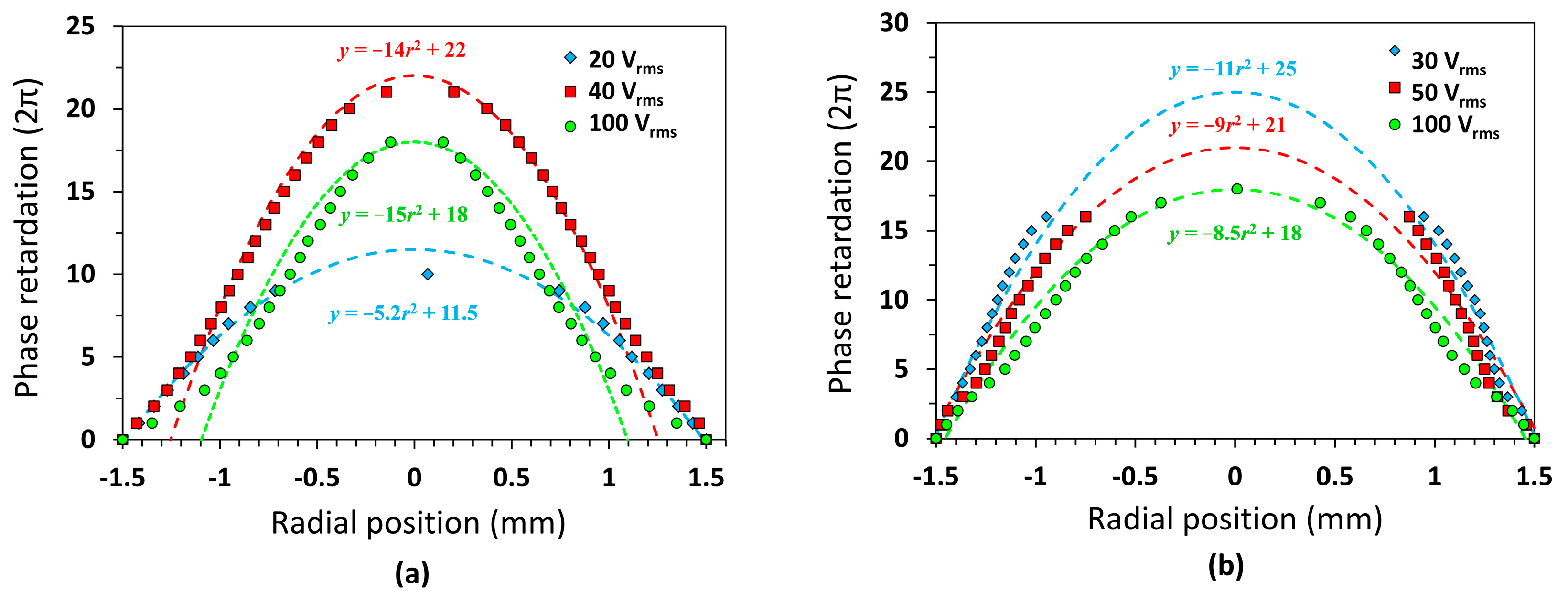
According to the results of the interference patterns in TLCL lenses, we deduced the profiles of the radial phase retardation that was individually generated in the LCL-1 and LCL-2 layers with respect to various applied voltages, as shown in Figure 7. The solid symbol and dash lines denote the measured results and quadratic curve fitting. In addition, the quadratic curve fitting equation (y = −ar2 + b) is shown in figures, where a = 1/2λf and b is maximum phase retardation. The theoretical value of focal length is obtained from a quadratic curve fitting equation [23]. Optimal results were observed when applying 40 Vrms in the LCL-2 layer, with which the shortest focal length was achieved. The focal length observed was consistent between the measured value of 5.41 cm and the theoretical value of 5.64 cm.
Finally, the LCL-2 layer of the TCLC lens was filled with an LC mixture with 3 wt % RM257. This layer was further processed with UV photo exposure at applied voltages of 40 Vrms to generate polymer networks in order to fix interference patterns. Then, the E7 LCs were filled into the LCL-1 layer to complete the TLCL lens. The images in the top row of Figure 8 show interference patterns in the TLCL lens with UV exposure process when 10, 50, and 100 Vrms were applied. Simultaneously, photos of an object labeled “NCKU” were taken using a CCD camera to demonstrate the imaging performance of the completed TCLC lens, as shown in the bottom row images. A linear polarizer was placed between the TLCL lens and CCD camera to ensure that only the light polarization parallel to the rubbing alignment of the LC lens could be recorded [35]. After applying 10 Vrms, the 90° TN cell turned, but the LC molecules in the LCL-1 layer did not reorient, given that 10 Vrms was below the threshold operating voltages. Therefore, all radial phase retardation was observed only from the fixed LC orientation in the LCL-2 layer. A magnified image of “NCKU” with a focal length of 5.41 cm is shown in Figure 8a.
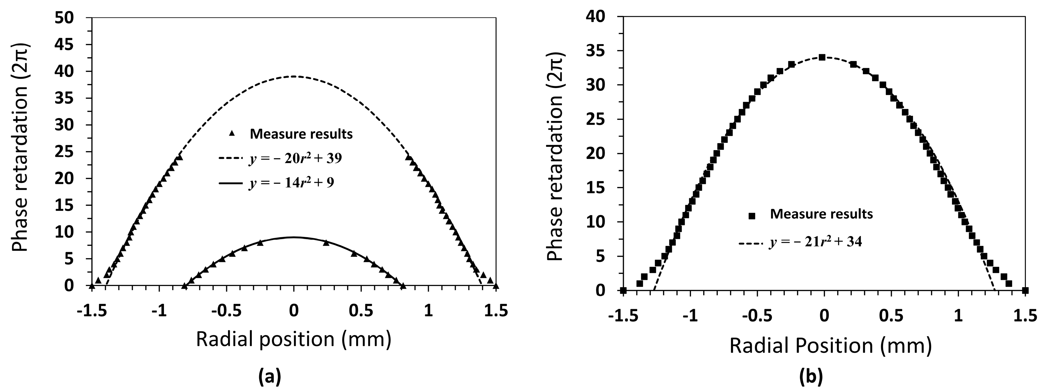
After applying voltages of 50 Vrms, Figure 8b shows the reoriented LCs in the LCL-1 layer and the contributed radial phase retardation near the boundary of the lens aperture. Thus, the total interference patterns from reoriented LCs in the LCL-1 and LCL-2 layers generated two obvious domains that corresponded to the coaxial bi-focus. The radial phase retardation profiles of the two individual domains are shown in Figure 9a. Using quadratic curve fitting, the theoretical focal lengths from the boundary and the central domains of the TLCL lens were 3.95 cm and 5.64 cm, respectively. In contrast, the measured focal lengths for the two domains were 4.22 cm and 5.41 cm, as shown in Figure 10. In conclusion, two different degrees of blurring of the images of the “NCKU” object were observed, as shown in Figure 8b, given that the TLCL lens operated in the coaxial bi-focus mode.
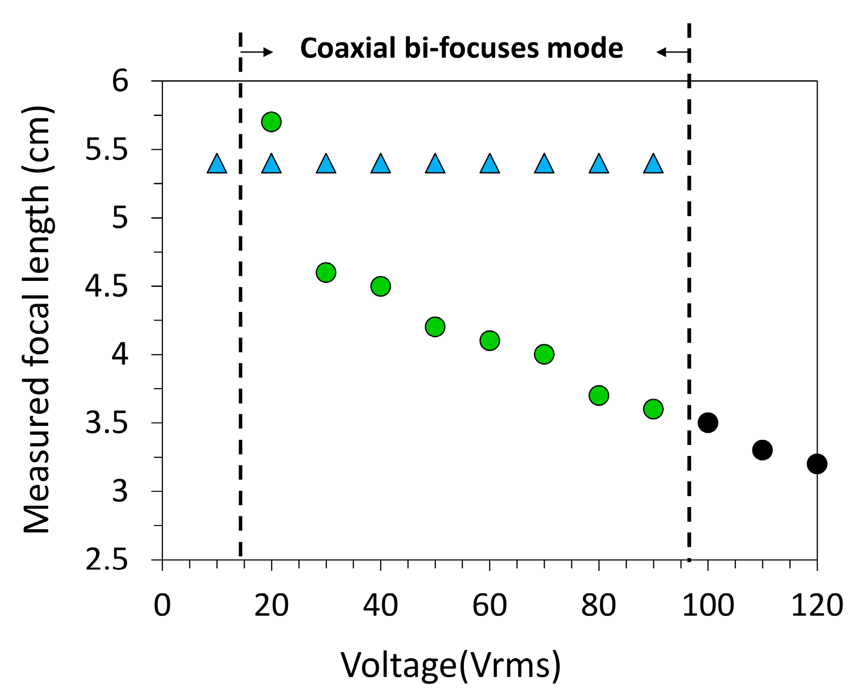
As shown in Figure 9b, the interference patterns from the LCs in the LCL-1 and LCL-2 layers were fully distributed over the entire lens aperture after 100 Vrms were applied to achieve the single-focus mode of the TLCL lens. As a result, the radial phase retardation profile increased. Here, the TLCL lens possessed a shorter focal length to obtain a single blurred image in the entire lens aperture, as shown in Figure 8c. The theoretical and measured focal lengths were 3.76 and 3.51 cm, respectively. The measurements of the electrically tunable focal lengths of the TLCL lens are listed in Figure 10. The electrical operation for the coaxial bi-focus mode ranged from 20 to 90 Vrms. This setting was achieved by combining a lens with one fixed focal length (5.41 cm) and another with electrically tunable focal lengths. The TLCL lens shows the shortest focal length of 3.24 cm at 120 Vrms.
4. Conclusions
We demonstrated a hole-patterned electrode LC lens called the TLCL lens that is capable of switching between tuning coaxial bi-focus and single-focus modes. The TLCL lens possesses larger focusing power compared with conventional hole-patterned electrode LC lenses. As a result, the lens can achieve a focal length of 5.41 cm, that is, 18.5 Diopter of focusing power, with operating voltages of 10 Vrms on the TN cell in order to turn on lens function. When increasing the applied voltages, the LC lens can be operated in coaxial bi-focus mode, an optical property which has a high potential for applications in 2D–3D switchable integral imaging systems with improved depth of field [36,37]. In addition, a short focal length of 3.24 cm (30.9 Diopter) was achieved at 120 Vrms, which is also suitable for AR applications [27]. However, applying higher voltages and radial phase retardation profiles to the TCLC lenses will be needed in future improvements. Some experiments are underway, including the usage of LCs with a larger dielectric anisotropy, optimal cell gaps in both LCL-1 and LCL-2 layers, and electrical operation with two independent voltage schemes [23].
Acknowledgments
The authors would like to thank the Ministry of Science and Technology (MOST) for financially supporting this research under Grant No. MOST 104-2221-E-006-185-MY3.
Author Contributions
Chun-Yu Chien and Chia-Rong Sheu conceived and designed the experiments; Cheng-Hau Li performed the experiments; Chia-Rong Sheu supervised the study; Chun-Yu Chien wrote the paper; all authors reviewed the manuscript.
Conflicts of Interest
The authors declare no conflict of interest.
References
- Li, L.; Bryant, D.; Heugten, T.V.; Bos, P.J. Near-diffraction-limited and low-haze electro optical tunable liquid crystal lens with floating electrodes. Opt. Express 2013, 21, 8371–8381. [Google Scholar] [CrossRef] [PubMed]
- Chien, C.Y.; Hsu, C.J.; Chen, Y.W.; Tseng, S.H.; Sheu, C.R. Holographic polymer networks formed in liquid crystal phase modulators via a He-Ne laser to achieve ultra-fast optical response. Opt. Express 2016, 24, 7534–7542. [Google Scholar] [CrossRef] [PubMed]
- Chen, H.; Peng, F.; Luo, Z.; Xu, D.; Wu, S.T.; Li, M.C.; Lee, S.L.; Tsai, W.C. High performance liquid crystal displays with a low dielectric constant material. Opt. Mater. Express 2014, 4, 2262–2273. [Google Scholar] [CrossRef]
- Chien, C.Y.; Sheu, C.R. Small dosage of holographic exposure via a He-Ne laser to fabricate tunable liquid crystal phase gratings operated with low electric voltages. Liq. Cryst. 2017, 44, 854–862. [Google Scholar] [CrossRef]
- Tan, J.; Song, Y.; Zhu, J.L.; Ni, S.B.; Wang, Y.J.; Sun, X.Y.; Lu, J.G.; Yang, B.R.; Shieh, H.P.D. Blue phase LC/polymer Fresnel lens fabricated by holographics. J. Disp. Technol. 2014, 10, 157–161. [Google Scholar] [CrossRef]
- Lin, S.H.; Huang, B.Y.; Li, C.Y.; Yu, K.Y.; Chen, J.L.; Kuo, C.T. Electrically and optically tunable Fresnel lens in a liquid crystal cell with a rewritable photoconductive layer. Opt. Mater. Express 2016, 6, 2229–2235. [Google Scholar] [CrossRef]
- Li, G.; Valley, P.; Giridhar, M.S.; Mathine, D.L.; Meredith, G.; Haddock, J.N.; Kippelen, B.; Peyghambarian, N. Large-aperture switchable thin diffractive lens with interleaved electrode patterns. Appl. Phys. Lett. 2006, 89, 141120. [Google Scholar] [CrossRef]
- Lou, Y.; Chen, L.; Wang, C.; Shen, S. Tunable-focus liquid crystal Fresnel zone lens based on harmonic diffraction. Appl. Phys. Lett. 2012, 101, 221121. [Google Scholar] [CrossRef]
- Ren, H.; Wu, S.T. Adaptive liquid crystal lens with large focal length tenability. Opt. Express 2006, 14, 11292–11298. [Google Scholar] [CrossRef] [PubMed]
- Serra, F.; Gharbi, M.A.; Luo, Y.; Liu, I.B.; Bade, N.D.; Kamien, R.D.; Yang, S.; Stebe, K.J. Curvature-driven, one-step assembly of reconfigurable smectic liquid crystal “compound eye” lenses. Adv. Opt. Mater. 2015, 3, 1287–1292. [Google Scholar] [CrossRef]
- Popov, P.; Honaker, L.W.; Mirheydari, M.; Mann, E.K.; Jákli, A. Chiral nematic liquid crystal microlenses. Sci. Rep. 2017, 7, 1603. [Google Scholar] [CrossRef] [PubMed]
- Ye, M.; Sato, S. Optical properties of liquid crystal lens of any size. Jpn. J. Appl. Phys. 2002, 41, L571–L573. [Google Scholar] [CrossRef]
- Hsu, C.J.; Jhang, J.J.; Huang, C.Y. Large aperture liquid crystal lens with an imbedded floating ring electrode. Opt. Express 2016, 24, 16722–16731. [Google Scholar] [CrossRef] [PubMed]
- Shibuya, G.; Yoshida, H.; Ozaki, M. High-speed driving of liquid crystal lens with weakly conductive thin films and voltage booster. Appl. Opt. 2015, 54, 8145–8151. [Google Scholar] [CrossRef] [PubMed]
- Chen, M.S.; Chen, P.J.; Chen, M.; Lin, Y.H. An electrically tunable imaging system with separable focus and zoom functions using composite liquid crystal lenses. Opt. Express 2014, 22, 11427–11435. [Google Scholar] [CrossRef] [PubMed]
- Lin, Y.H.; Chen, H.S. Electrically tunable-focusing and polarizer-free liquid crystal lenses for ophthalmic applications. Opt. Express 2013, 21, 9428–9436. [Google Scholar] [CrossRef] [PubMed]
- Ye, M.; Wang, B.; Uchida, M.; Yanase, S.; Takahashi, S.; Sato, S. Focus tuning by liquid crystal lens in imaging system. Appl. Opt. 2012, 51, 7630–7635. [Google Scholar] [CrossRef] [PubMed]
- Lei, Y.; Tong, Q.; Zhang, X.; Sang, H.; Ji, A.; Xie, C. An electrically tunable plenoptic camera using a liquid crystal microlens array. Rev. Sci. Instrum. 2015, 86, 053100. [Google Scholar] [CrossRef] [PubMed]
- Algorri, J.F.; Urruchi, V.; Bennis, N.; Morawiak, P.; Sánchez-Pena, M.J.; Otón, J.M. Integral imaging capture system with tunable field of view based on liquid crystal microlenses. IEEE Photonics Technol. Lett. 2016, 28, 1854–1857. [Google Scholar] [CrossRef]
- Wang, Y.J.; Shen, X.; Lin, Y.H.; Javidi, B. Extended depth-of-field 3D endoscopy with synthetic aperture integral imaging using an electrically tunable focal-length liquid-crystal lens. Opt. Lett. 2015, 40, 3564–3567. [Google Scholar] [CrossRef] [PubMed]
- Hassanfiroozi, A.; Huang, Y.P.; Javidi, B.; Shieh, H.P.D. Dual layer electrode liquid crystal lens for 2D/3D tunable endoscopy imaging system. Opt. Express 2016, 24, 8527–8538. [Google Scholar] [CrossRef] [PubMed]
- Hassanfiroozi, A.; Huang, Y.P.; Javidi, B.; Shieh, H.P.D. Hexagonal liquid crystal lens array for 3D endoscopy. Opt. Express 2015, 23, 971–981. [Google Scholar] [CrossRef] [PubMed]
- Ye, M.; Wang, B.; Sato, S. Liquid-crystal lens with a focal length that is variable in a wide range. Appl. Opt. 2004, 43, 6407–6412. [Google Scholar] [CrossRef] [PubMed]
- Hsu, C.J.; Sheu, C.R. Preventing occurrence of disclination lines in liquid crystal lenses with a large aperture by means of polymer stabilization. Opt. Express 2011, 19, 14999–15008. [Google Scholar] [CrossRef] [PubMed]
- Kao, Y.Y.; Chao, P.C.P. A New dual-frequency liquid crystal lens with ring-and-pie electrodes and a driving scheme to prevent disclination lines and improve recovery time. Sensors 2011, 11, 5402–5415. [Google Scholar] [CrossRef] [PubMed]
- Ye, M.; Wang, B.; Sato, S. Driving of liquid crystal lens without disclination occurring by applying in-plane electric field. Jpn. J. Appl. Phys. 2003, 42, 5086–5089. [Google Scholar] [CrossRef]
- Zhao, X.; Liu, C.; Zhang, D.; Luo, Y. Tunable liquid crystal microlens array using hole patterned electrode structure with ultrathin glass slab. Appl. Opt. 2012, 51, 3024–3030. [Google Scholar] [PubMed]
- Shen, X.; Wang, Y.J.; Chen, H.S.; Xiao, X.; Lin, Y.H.; Javidi, B. Extended depth-of-focus 3D micro integral imaging display using a bifocal liquid crystal lens. Opt. Lett. 2015, 40, 538–541. [Google Scholar] [CrossRef] [PubMed]
- Liu, S.; Hua, H. Time-multiplexed dual-focal plane head-mounted display with a liquid lens. Opt. Lett. 2009, 34, 1642–1644. [Google Scholar] [CrossRef] [PubMed]
- Ren, H.; Fox, D.W.; Wu, B.; Wu, S.T. Liquid crystal lens with large focal length tunability and low operating voltage. Opt. Express 2007, 15, 11328–11335. [Google Scholar] [CrossRef] [PubMed]
- Lin, H.C.; Lin, Y.H. A fast response and large electrically tunable-focusing imaging system based on switching of two modes of a liquid crystal lens. Appl. Phys. Lett. 2010, 97, 063505. [Google Scholar] [CrossRef]
- Wang, B.; Ye, M.; Honma, M.; Nose, T.; Sato, S. Liquid crystal lens with spherical electrode. Jpn. J. Appl. Phys. 2002, 41, L1232–L1233. [Google Scholar] [CrossRef]
- Lin, H.C.; Lin, Y.H. An electrically tunable focusing liquid crystal lens with a built-in planar polymeric lens. Appl. Phys. Lett. 2011, 98, 083503. [Google Scholar] [CrossRef]
- Zhao, X.; Zhang, D.; Luo, Y.; Liu, C. Numerical analysis and design of patterned electrode liquid crystal microlens array with dielectric slab. Opt. Laser Technol. 2012, 44, 1834–1839. [Google Scholar]
- Hsu, C.J.; Sheu, C.R. Using photopolymerization to achieve tunable liquid crystal lenses with coaxial bifocals. Opt. Express 2012, 20, 4738–4746. [Google Scholar] [CrossRef] [PubMed]
- Choi, H.; Park, J.H.; Hong, J.; Lee, B. Depth-enhanced integral imaging with a stepped lens array or a composite lens array for three-dimensional display. Jpn. J. Appl. Phys. 2004, 43, 5330–5336. [Google Scholar] [CrossRef]
- Jang, J.S.; Javidi, B. Large depth-of-focus time-multiplexed three-dimensional integral imaging by use of lenslets with nonuniform focal lengths and aperture sizes. Opt. Lett. 2003, 28, 1924–1926. [Google Scholar] [CrossRef] [PubMed]
Figure 1.
Schematic cross-section of the proposed LC lens and two major decomposed parts for the purpose of simulation design: (a) The proposed structure of the TLCL LC lens; (b) Decomposed part one (LCL-1); (c) Decomposed part two (LCL-2).
Figure 1.
Schematic cross-section of the proposed LC lens and two major decomposed parts for the purpose of simulation design: (a) The proposed structure of the TLCL LC lens; (b) Decomposed part one (LCL-1); (c) Decomposed part two (LCL-2).

Figure 2.
Scheme of the major fabrication process of the TLCL LC lens: (a) Structure of the TLCL lens; (b) Processing of the LC mixture filled in the LCL-2 layer via UV exposure and applying voltages to fix the LC molecular orientation via RM257 polymer networks; (c) Filling E7 LCs into the 25 μm gap (LCL-1) to achieve LC lens fabrication.
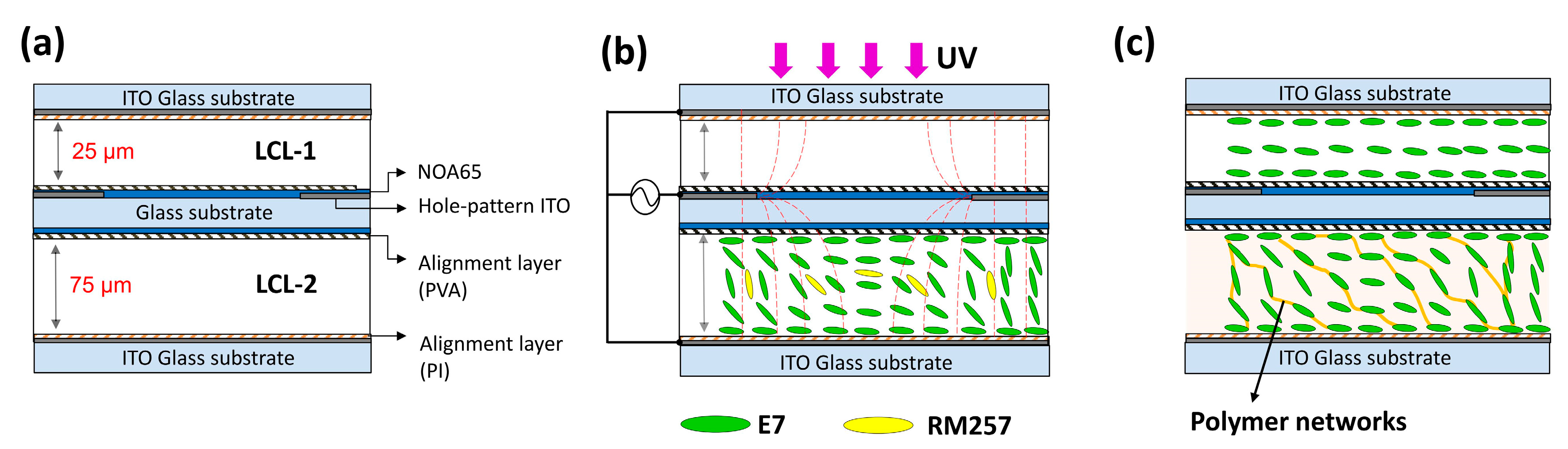
Figure 3.
Scheme of the electric operation of the TCLC lens: (a) Lens operation in the off-state; (b) Lens operation in the on-state with tunable coaxial bi-focus characteristics; (c) Lens operation in the on-state with tunable single focus, which yields a higher focusing power and shorter focal lengths. One applied voltage of V1 was in the range between 20 and 90 Vrms and the other applied voltage of V2 was over 90 Vrms.
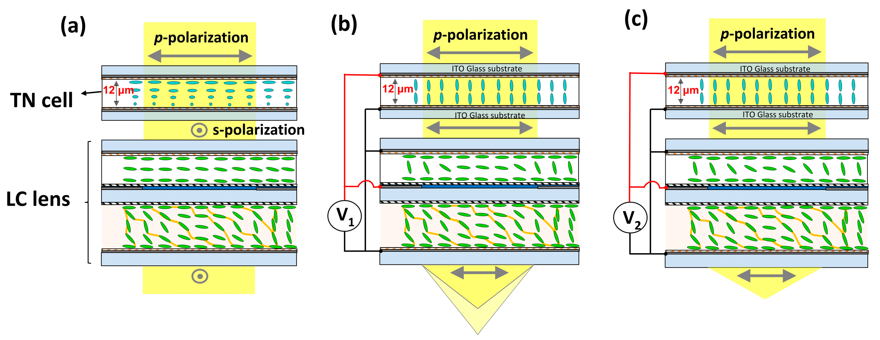
Figure 4.
Quantitative comparisons of the interference patterns in LC lenses with different conditions: Conventional LC lens without an insulator layer at a voltage of (a) 20 Vrms (b) 40 Vrms, and (c) 100 Vrms. Conventional LC lens with an insulator of 1.1 mm glass substrate at a voltage of (d) 20 Vrms (e) 40 Vrms, and (f) 100 Vrms. TLCL lens at a voltage of (g) 20 Vrms (h) 40 Vrms, and (i) 100 Vrms. The double-head arrows indicate the rubbing direction of the LC alignments indicated by R; the polarization directions of a pair of crossed polarizers are indicated by A and P.

Figure 5.
Comparison of the electrical equipotential line distribution in TLCL and conventional lenses via simulation at the same voltages: (a) Only considering LCs filled in the LCL-2 layer with a thickness of 75 μm; (b) Only considering LCs filled in the LCL-1 layer with a thickness of 25 μm. The areas marked with closed red curves indicate the occurrence of disclination lines.
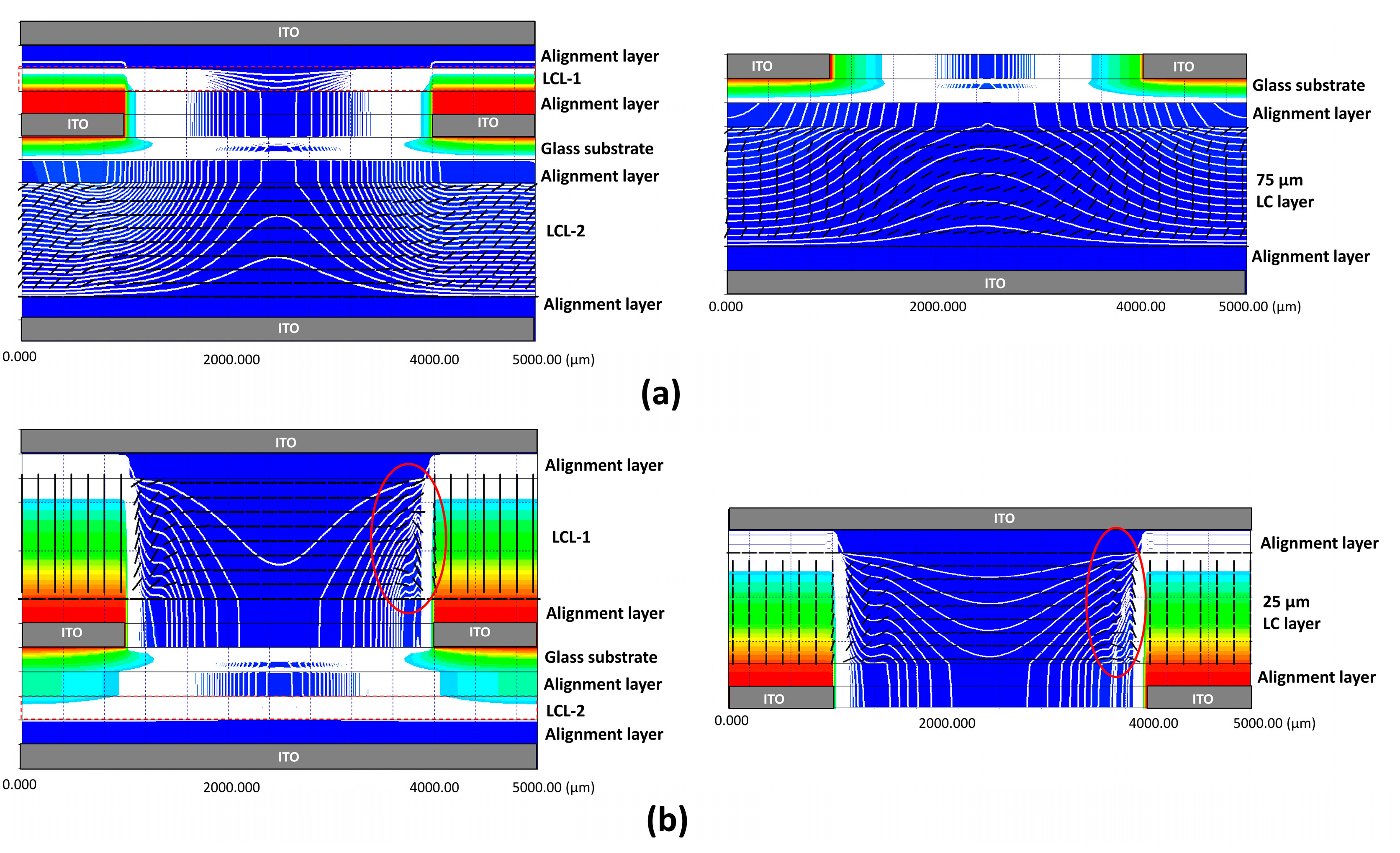
Figure 6.
Comparisons of the interference patterns between the conventional LC lens and the TLCL lens. The interference patterns in (a–c) belong to the conventional LC lens without an insulator layer. The occurrence of a disclination line can be observed in the results. By contrast, the interference patterns in (d–f) belong to the TLCL lens when specially applying voltages, which show no disclination lines.
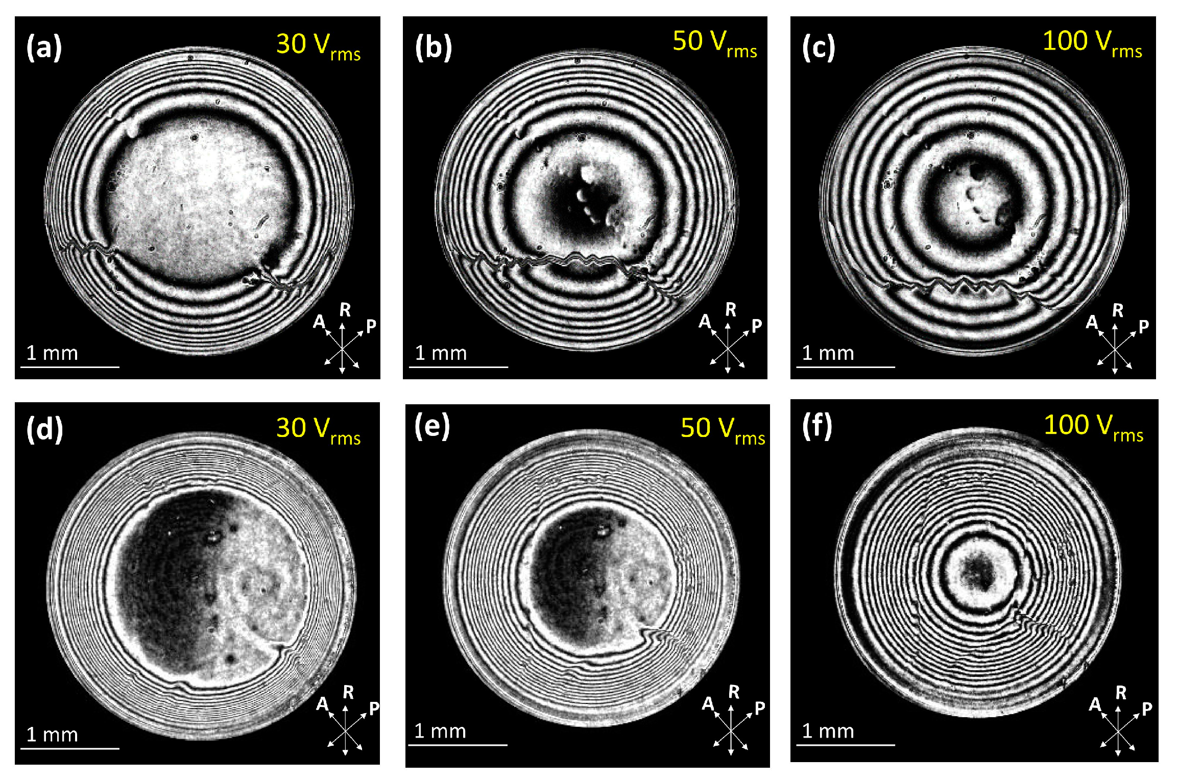
Figure 7.
The radial phase retardation profiles of the TLCL lens with respect to various applied voltages: (a) Radial phase retardation in the LCL-2 layer is the same as the interference patterns in Figure 4g–i; (b) Radial phase retardation in the LCL-1 layer is same as the interference patterns in Figure 5d–f.

Figure 8.
Interference patterns and imaging performance of the TLCL lens with electrically switching modes of coaxial bi-focus and single focus: individually operating at voltages of: (a) 10 Vrms; (b) 50 Vrms; (b) 100 Vrms. The black dash circles indicate the boundary of the lens aperture.
Figure 8.
Interference patterns and imaging performance of the TLCL lens with electrically switching modes of coaxial bi-focus and single focus: individually operating at voltages of: (a) 10 Vrms; (b) 50 Vrms; (b) 100 Vrms. The black dash circles indicate the boundary of the lens aperture.
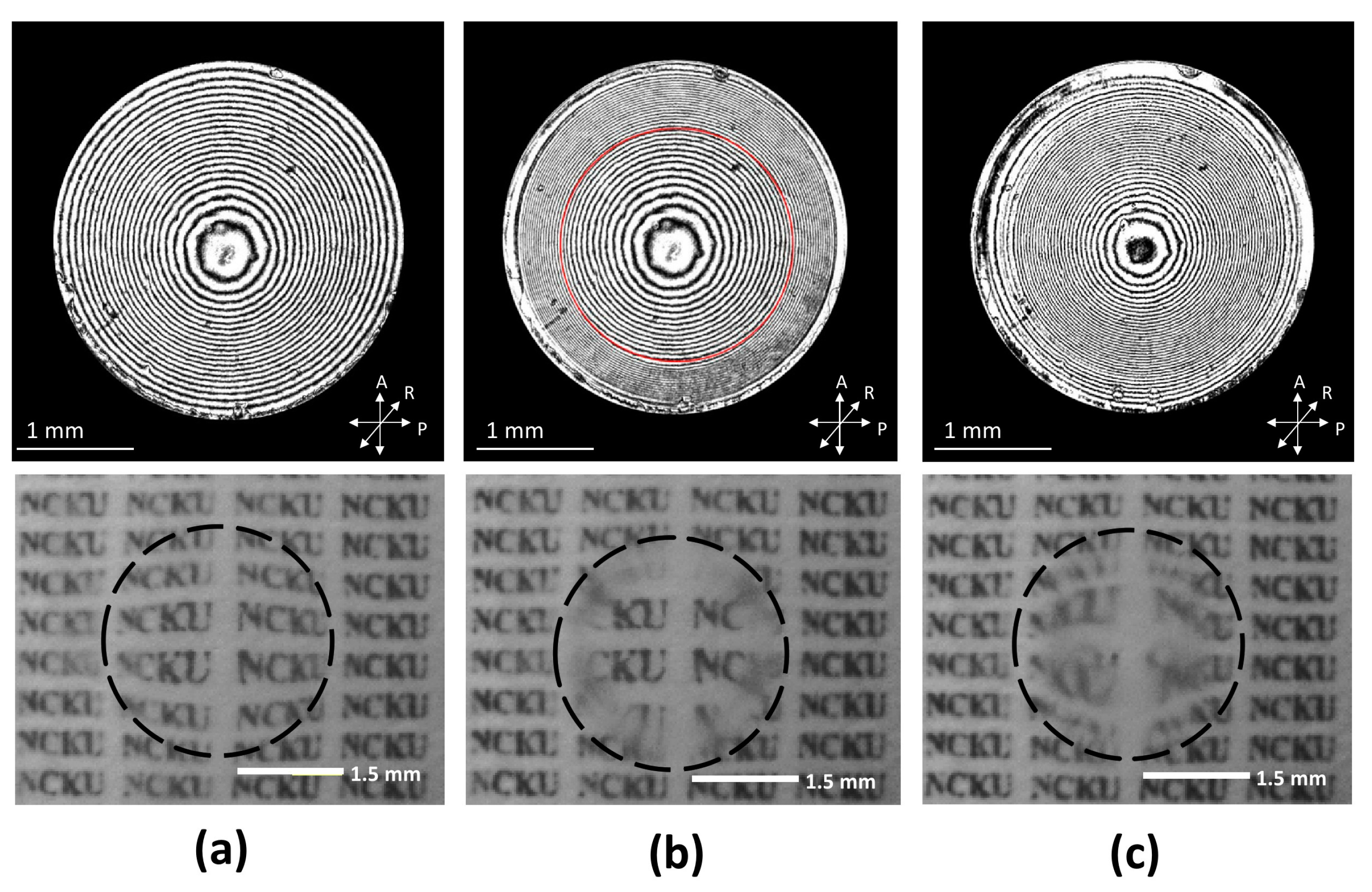
Figure 9.
The radial phase retardation profiles of the TLCL lens with various operating voltages: (a) 50 Vrms; (b) 100 Vrms. The dash curves denote the quadratic curve fitting.
Figure 9.
The radial phase retardation profiles of the TLCL lens with various operating voltages: (a) 50 Vrms; (b) 100 Vrms. The dash curves denote the quadratic curve fitting.

Figure 10.
The measurements of the electrically tunable focal lengths in the TLCL lens with switching coaxial bi-focus and single focus modes; the blue solid triangles denote the fixed focal length from the LCs in the LCL-2 layer; the green solid circles denote the electrically tunable focal lengths from the LCs in the LCL-1 layer; and the black solid circles denote the electrically tunable focal lengths in single focus mode at higher voltages.
© 2017 by the authors. Licensee MDPI, Basel, Switzerland. This article is an open access article distributed under the terms and conditions of the Creative Commons Attribution (CC BY) license (http://creativecommons.org/licenses/by/4.0/).
Share and Cite
MDPI and ACS Style
Chien, C.-Y.; Li, C.-H.; Sheu, C.-R. An Electrically Tunable Liquid Crystal Lens with Coaxial Bi-Focus and Single Focus Switching Modes. Crystals 2017, 7, 209. https://doi.org/10.3390/cryst7070209
AMA Style
Chien C-Y, Li C-H, Sheu C-R. An Electrically Tunable Liquid Crystal Lens with Coaxial Bi-Focus and Single Focus Switching Modes. Crystals. 2017; 7(7):209. https://doi.org/10.3390/cryst7070209
Chicago/Turabian StyleChien, Chun-Yu, Cheng-Hau Li, and Chia-Rong Sheu. 2017. "An Electrically Tunable Liquid Crystal Lens with Coaxial Bi-Focus and Single Focus Switching Modes" Crystals 7, no. 7: 209. https://doi.org/10.3390/cryst7070209
Note that from the first issue of 2016, this journal uses article numbers instead of page numbers. See further details here.