Article

The Role of Halogen Bonding in Controlling Assembly and Organization of Cu(II)-Acac Based Coordination Complexes

by
Janaka C. Gamekkanda
1,
Abhijeet S. Sinha
1,
John Desper
1,
Marijana Ðaković
2 and
Christer B. Aakeröy
1,*
1
Department of Chemistry, Kansas State University, Manhattan, KS 66506, USA
2
Department of Chemistry, Faculty of Science, University of Zagreb, Horvatovac 102a, HR-10000 Zagreb, Croatia
*
Author to whom correspondence should be addressed.
Crystals 2017, 7(7), 226; https://doi.org/10.3390/cryst7070226
Submission received: 23 June 2017 / Revised: 15 July 2017 / Accepted: 17 July 2017 / Published: 20 July 2017
(This article belongs to the Special Issue Analysis of Halogen and Other σ-Hole Bonds in Crystals)

Abstract

:
In order to explore the use of non-covalent interactions in the deliberate assembly of metal-supramolecular architectures, a series of β-diketone based ligands capable of simultaneously acting as halogen-bond donors and chelating ligands were synthesized. The three ligands, L1, L2, and L3, carry ethynyl-activated chlorine, bromine, and iodine atoms, respectively and copper(II) complexes of all three ligands were crystallized from different solvents, acetonitrile, ethyl acetate, and nitromethane in order to study specific ligand-solvent interaction. The free ligands L2 and L3, with more polarizable halogen atoms, display C-X⋯O halogen bonds in the solid state, whereas the chloro-analogue (L1) does not engage in halogen bonding. Both acetonitrile and ethyl acetate act as halogen-bond acceptors in Cu(II)-complexes of L2 and L3 whereas nitromethane is present as a ‘space-filling’ guest without participating in any significant intermolecular interactions in Cu(II)-complexes of L2. L3, which is decorated with an iodoethynyl moiety and consistently engages in halogen-bonds with suitable acceptors. This systematic structural analysis allows us to rank the relative importance of a variety of electron-pair donors in these metal complexes.

1. Introduction

Effective practical crystal engineering relies on the deceptively simple act of molecular recognition which [1], in turn, is achieved by balancing geometric compatibility with a multitude of reversible and relatively weak non-covalent forces [2,3,4,5]. As a result, the directed assembly of compositionally and structurally complex architectures requires a thorough understanding of the way in which complementary and competing forces eventually lead to a stable solid-state architecture [6,7]. Against this background, our goal was to establish reliable and robust avenues for the design and synthesis of crystalline metal-containing materials by encoding each building-block with structural-preferences that lead to “programmable” and predictable assembly [8,9,10].
There are many reported examples of crystal engineering involving coordination complexes as building blocks for a variety of supramolecular assemblies of different dimensionalities e.g., 1-D [8], 2-D [8,11,12], and 3-D [11,13]. Examples of synthetic vectors for metal-based supramolecular synthesis include π⋯π [14,15,16], cation⋯π [17], anion⋯π [16,18,19], lone-pair⋯π [16,19,20], and metal⋯π [21,22] interactions, but the most common non-covalent interaction for such ventures is arguably the hydrogen bond [23,24,25,26,27]. Despite the relative frequent use of hydrogen bonds [28,29], such interactions are not always ideal since many hydrogen-bond donors (i.e., amines, oximes, and carboxylic acids) may forge unwanted coordinate-covalent bonds with the metal-ion leading to undesirable assemblies and architectures. As a more effective synthetic alternative, the halogen bond may be a possibility as halogen-bond donors do not inherently include a moiety that can potentially act as a structurally disruptive ligand for the metal ion. According to the IUPAC recommendations in 2013 [30], a halogen bond is defined as follows; “A halogen bond occurs when there is evidence of a net attractive interaction between an electrophilic region associated with a halogen atom in a molecular entity and a nucleophilic region in another, or the same, molecular entity”. This attractive interaction between a halogen atom and an electronegative atom can facilitate a vast variety of applications in different fields including material science, synthetic chemistry, polymer science, and in bimolecular systems [28,29,31,32]. By combining halogen-bonded systems with metals [33,34], metallosupramolecular assemblies have been discovered with several important properties including redox, magnetic, non-linear optical, gas adsorption, and catalytic properties [35,36].
Another possible hindrance to reliable supramolecular chemistry of metal complexes is caused by negatively charged counter ions as they frequently coordinate to the metal ion in such a way that any intended assembly strategy (or other non-covalent interactions) is scuppered. Therefore, the need for charge-balancing ions should be avoided, if at all possible, by using charged ligands that balance the oxidation state of the metal ions in the system. With this in mind β-diketones (acac) can be employed as simple and highly efficient metal-chelating ligands and the acidic hydrogen atom of acac can be easily removed to generate a negative charge on this binding site which can avoid the need for additional counter ions, Scheme 1.
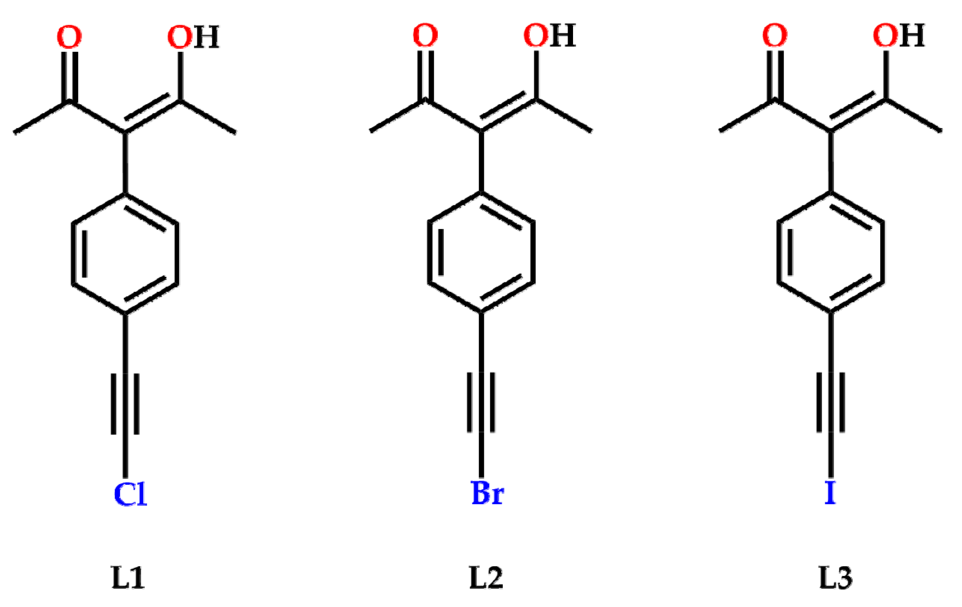
An earlier study on the possible use of halogen bonds in this synthetic context involved the combination of Cu(II) ions and acac-based ligands substituted with a halogen atom [37]. However, structure-directing halogen-bonds were not observed largely due to the fact that the halogen atoms had not been ‘activated’ with the aid of adjacent electron-withdrawing groups [38,39,40,41] or through an sp-hybridized carbon atom [42,43]. In order to modify this early strategy, we synthesized three new ligands (L1L3) where the halogen atom was replaced with a haloethynyl species (Scheme SI). They all contain the necessary acac-moiety but by increasing the electrophilic σ-hole on the halogen-bond donor they may offer more pronounced structure-directing vectors, Scheme 2.
In each free ligand, one can envision that there are four competing halogen-bond acceptor sites; a lone pair on the keto oxygen atom, the hydroxylic oxygen atom, the π-electron cloud on the ethynyl group and the electronegative equatorial region on each halogen atom, Scheme 3a. In the corresponding metal complexes we reduce the number of unique competing halogen-bond acceptors to three; an oxygen atom from the deprotonated acac-moiety, as well as the triple bond, and the equatorial region on the halogen atom, Scheme 3b. The purpose of this synthetic/structural study is to establish which of these different acceptor sites is going to dominate the eventual solid-state structures.

2. Results

In the crystal structure of L1, there are no significant halogen bonds present involving the chloroethynyl moiety, and adjacent L1 molecules seem to be close packed (the ligand resides on a symmetry plane which gives the appearance of two –OH moieties). The acac moiety is almost perpendicular with respect to the adjacent phenyl ring and it also accepts a C-H⋯O hydrogen bond from an adjacent ligand, r(O⋯H) ca. 2.65 Å, (Figure 1).
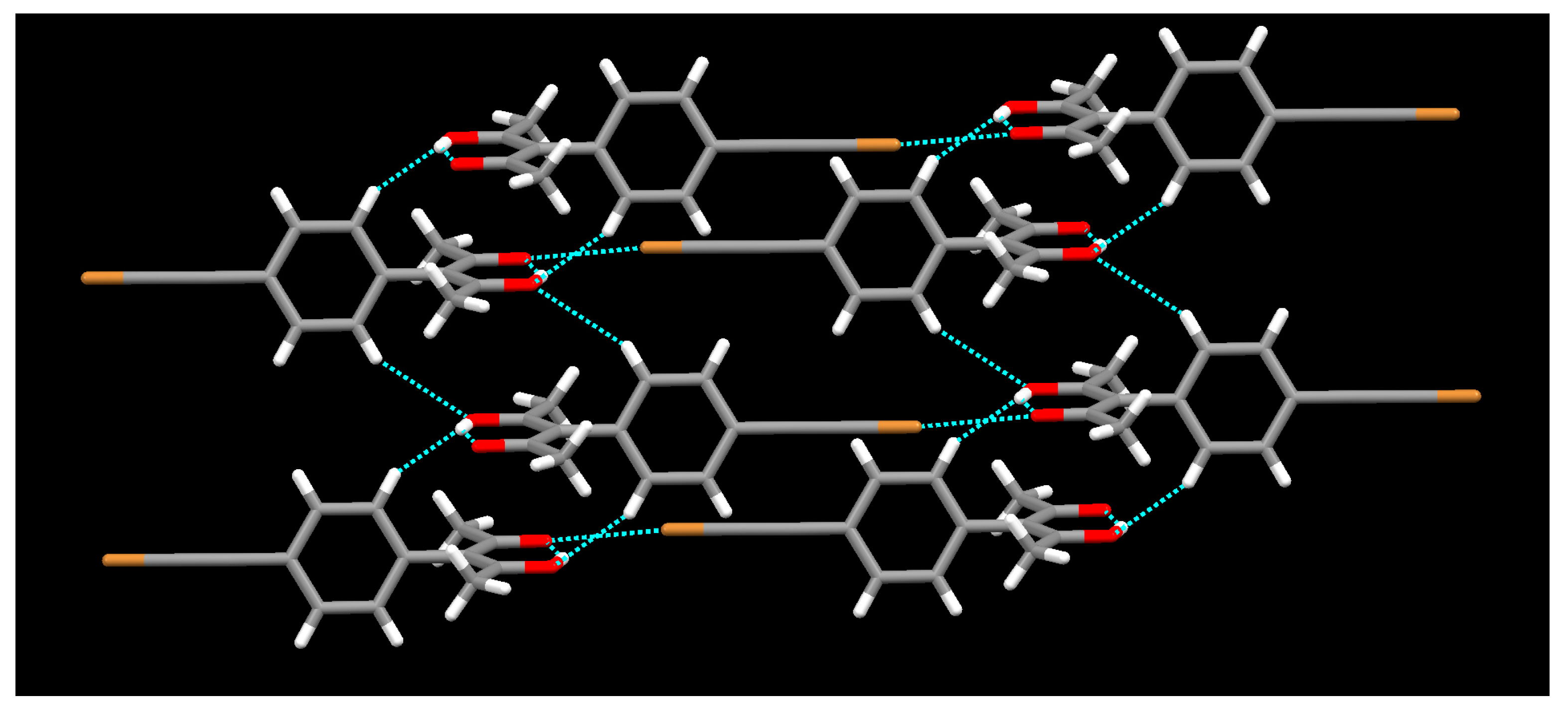
The crystal structures of L2, Figure 2, and L3, Figure 3, both contain short intermolecular contacts between their respective haloethynyl moieties and a keto oxygen atom of the acac group. These halogen bonds create infinite 1-D chains in both structures and short contacts in the structure of L2 r(O⋯Br) 2.98 Å, and in L3 r(O⋯I) 3.04 Å. The halogen bond involving the more polarizable iodine atom shows a slightly greater reduction in combined van der Waals radii (13% reduction) than the corresponding bromo species (11.6% reduction). In addition to halogen bonding there are C-H⋯O hydrogen bonds between phenyl-H and acac-O. In both structures oxygen makes bifurcated hydrogen bonding with phenyl-H and in L3 a symmetric hydrogen bond is observed with r(O⋯H) ca. 2.81 Å. Bifurcated hydrogen bonding distances in L2 are r(O⋯H) ca. 2.70 Å and 2.79 Å.
The intramolecular X-C≡C bond angles in L2 and L3 deviate slightly from linear at 174.14° and 172.44°, respectively. As expected, the C-X⋯O halogen-bond angle is more linear for the C-I⋯O bond (178.0°) than for the C-Br⋯O bond (170.8°). Again, the torsion angle which describes the orientation of the acac moiety with respect to the phenyl ring is close to 90° for both L2 and L3.
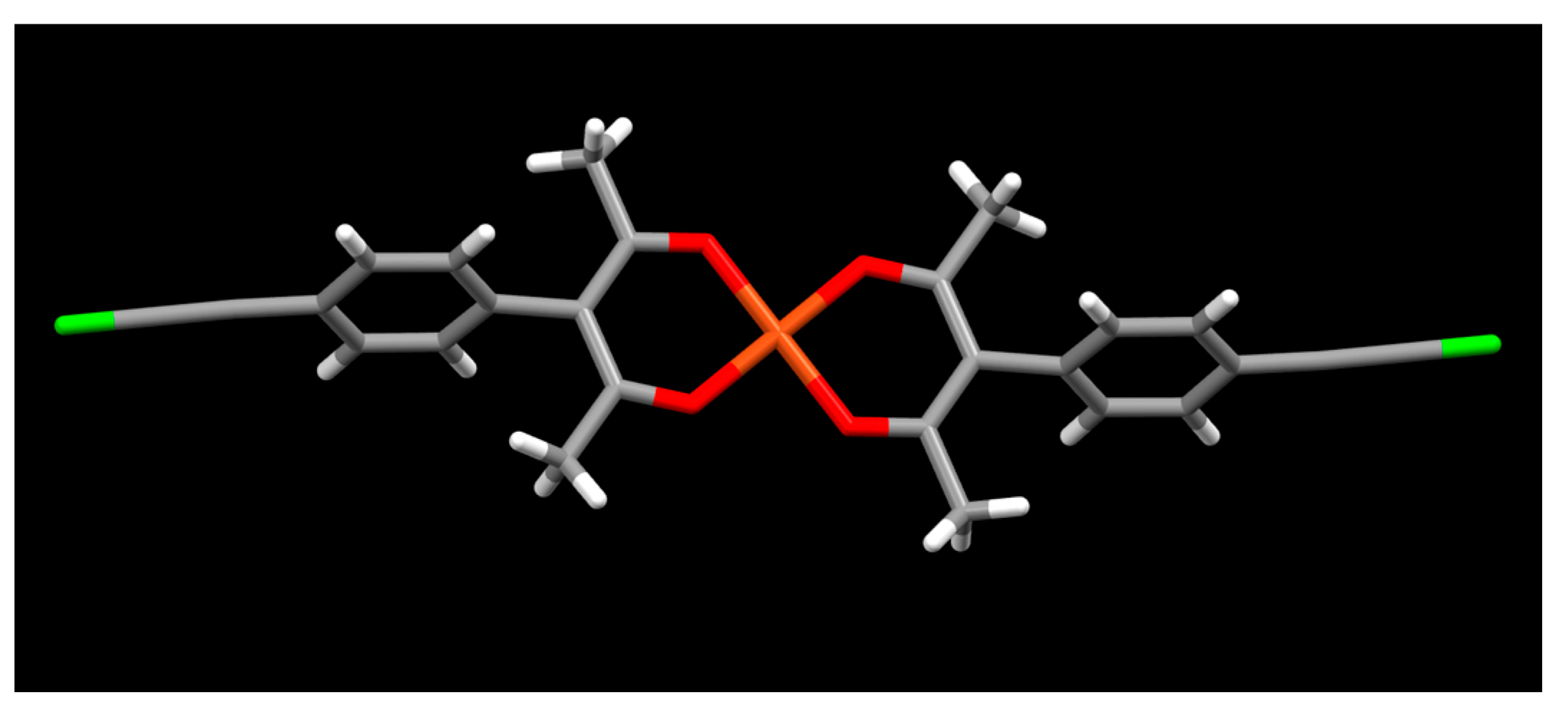
The reaction between L1 and Cu(II) produces a metal-complex with the expected ligand-metal ratio of 2:1 in a square-planar geometry (Figure 4). There are no prominent short intermolecular contacts involving the chloroethynyl moiety.
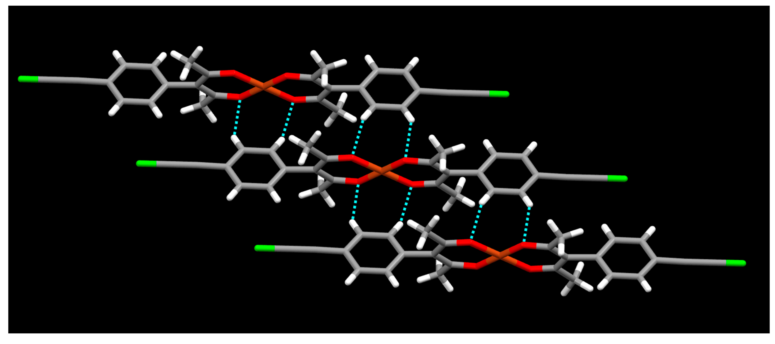
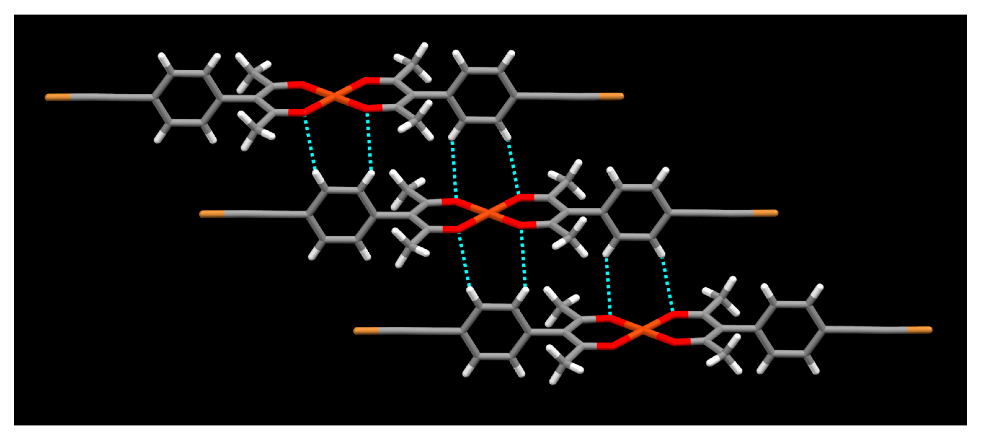
There are several C-H⋯O hydrogen bonds between the phenyl group and the acac moiety (Figure 5) r(O⋯H) ca. 2.70 Å and 2.94 Å and these interactions create an infinite stack of complex ions.
In the crystal structure of [Cu(L2)2]·2CH3CN, the 1:2 metal-ligand stoichiometry in a square planar geometry is observed again. However, in this case, the ligand which contains an “activated” bromine atom, forms a halogen bond with the acetonitrile solvent molecule; r(Br⋯N) 3.07 Å (a 9.7% vdW reduction), θ (C-Br⋯N) 172.05°, θ (Br⋯N≡C) 144.48° (Figure 6).
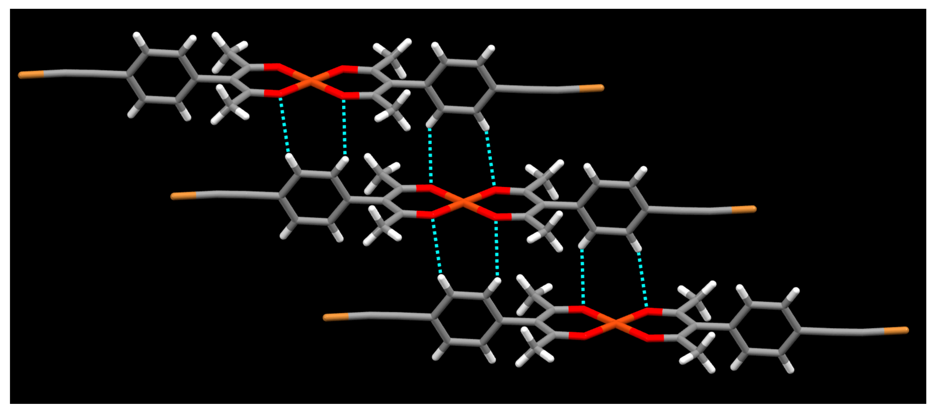
The only other notable interactions are the C-H⋯O hydrogen bonds between the phenyl ring and the acac group (Figure 7) r(O⋯H) ca. 2.57 Å and 2.73 Å. These hydrogen bonds create an infinite stack of complex ions similar to that observed in the structure of [Cu(L1)2].
When the reaction between L2 and copper(II) tetrafluoroborate was carried out in ethyl acetate, the outcome was a crystal structure with identical stoichiometry and overall shape as that found in the structure of [Cu(L2)2]·2CH3CN. The square-planar geometry is maintained and the activated bromine atom forms a halogen bond with the ethyl acetate solvent molecule; r(Br⋯O) 2.88 Å (a 14.5% vdW reduction), θ (C-Br⋯O) 171.07°, θ (Br⋯O=C) 126.47° (Figure 8).
Again, C-H⋯O hydrogen bonds between adjacent complex ions r(O⋯H) ca. 2.61 Å and 2.63 Å create an infinite stack (Figure 9).
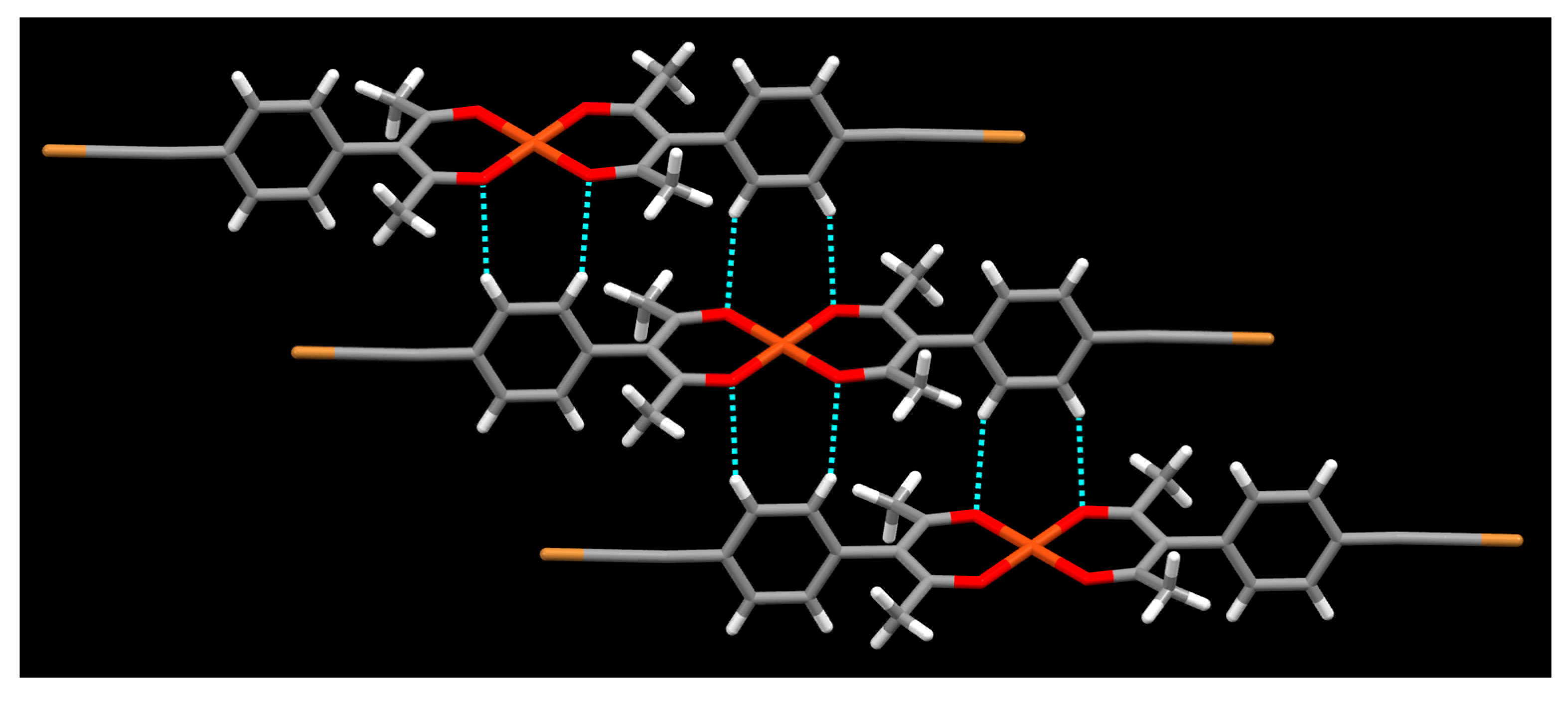
Even though halogen bonded iodo-nitromethane synthons are reported [44,45], in the metal ligand complex [Cu(L2)2]·2CH3NO2, nitromethane, which lacks halogen-bond acceptor sites that are effective with the relatively weak bromine atom, simply acts as non-directional space filling in the crystal structure (Figure 10). There are no prominent short contacts involving the bromoethynyl group. In the crystal packing, C-H⋯O hydrogen bonding between hydrogens of phenyl group and oxygen of acac moiety is observed (Figure 11) similar to the packing of [Cu(L2)2]·2C4H8O2. Both hydrogens of the phenyl group show interactions with acac oxygen atoms r(O⋯H) 2.50 Å and 2.57 Å.
Yet again, two C-H⋯O intermolecular hydrogen bonds between adjacent phenyl rings and acac-sites can be observed (Figure 11) r(O⋯H) ca. 2.50 Å and 2.57 Å producing the now familiar stack of complex ions.
The reaction between copper(II) tetrafluoroborate hydrate and L3 in acetonitrile produced a 1:2 metal-ligand complex with four solvent molecules included in the structure. Even though the metal center contains two acac ligands in a square planer arrangement, the overall geometry is octahedral as two acetonitrile molecules are axially coordinated to the Cu(II) ion. The activated iodine atom forms a halogen bond with the acetonitrile solvent molecule (Figure 12); r(I⋯N) 2.98 Å (a 15.6% vdW reduction), θ (C-I⋯N) 174.28°, θ (I⋯N≡C) 141.61°. This time there are no prominent C-H⋯O intermolecular interactions.
When the solvent is changed from acetonitrile to ethyl acetate the metal ion remains four-coordinate as there is no axial coordination of solvent molecules (Figure 13). There are, however, halogen bonds between the iodoethynyl group and the O=C group of ethyl acetate, r(I⋯O) 2.91 Å (a 20.0% vdW reduction), θ (C-I⋯O) 172.33°, θ (I⋯O=C) 128.19°.
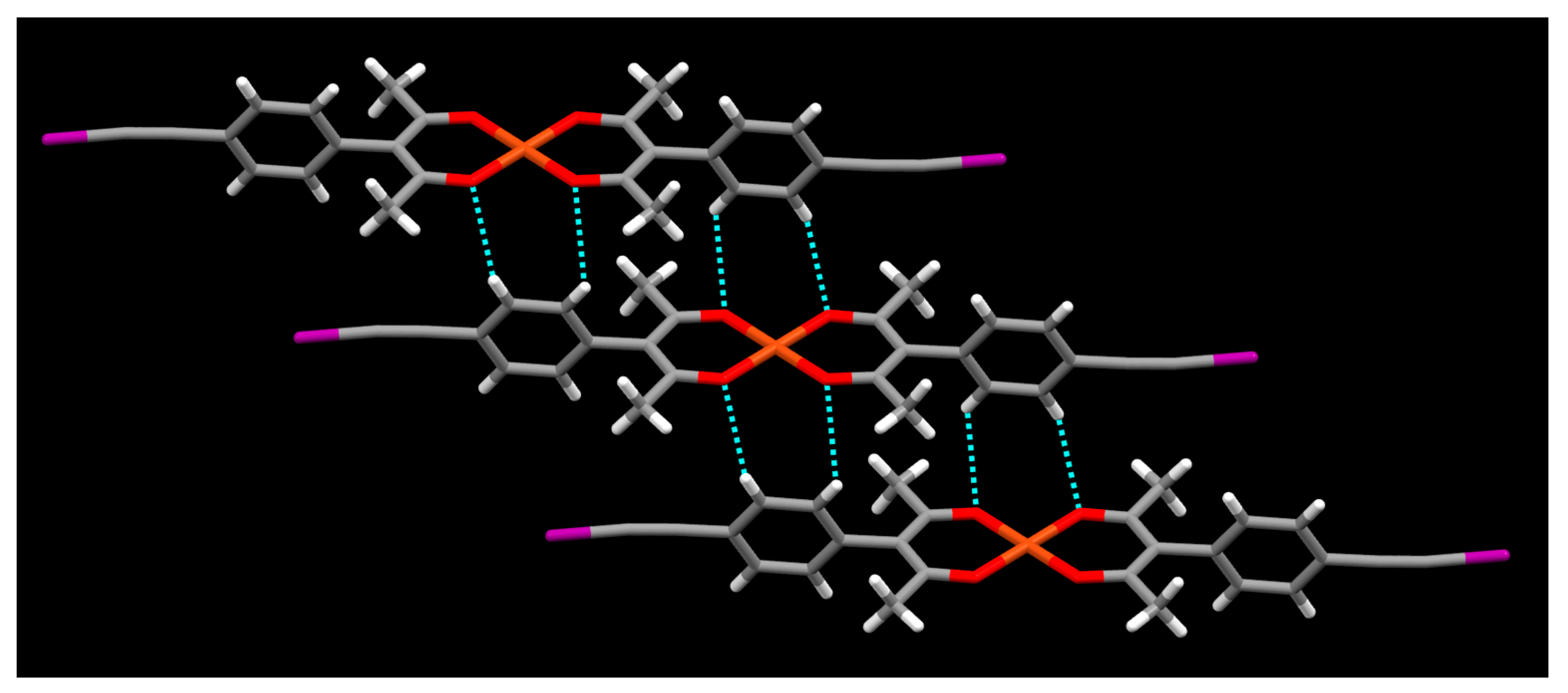
Without any axially coordinated ligands, adjacent complex ions are again close enough to form stacks as a result of intermolecular C-H⋯O hydrogen bonding between phenyl rings and acac moieties (Figure 14) ca. r(O⋯H) 2.63 Å and 2.76 Å.
In the absence of a solvent capable of acting as a competitive halogen-bond acceptor, the iodoethynyl group instead seeks out two different types of acceptor sites as found in the structure of [Cu(L3)2]. First, there is a bifurcated interaction with two oxygen atoms of the acac moiety (Figure 15) r(I⋯O) 3.31 Å and 3.29 Å, θ (C-I⋯O) 153.02°, and 157.72°, θ (I⋯O=C) 128.19°.
Second, there is a C-I⋯π interaction involving the triple bond (Figure 16) r(I⋯triple bond) 3.63 Å, θ (C-I⋯triple bond) 153.84°, θ (I⋯triple bond-I) 80.58° (geometric parameters calculated with respect to the center of the C≡C bond).
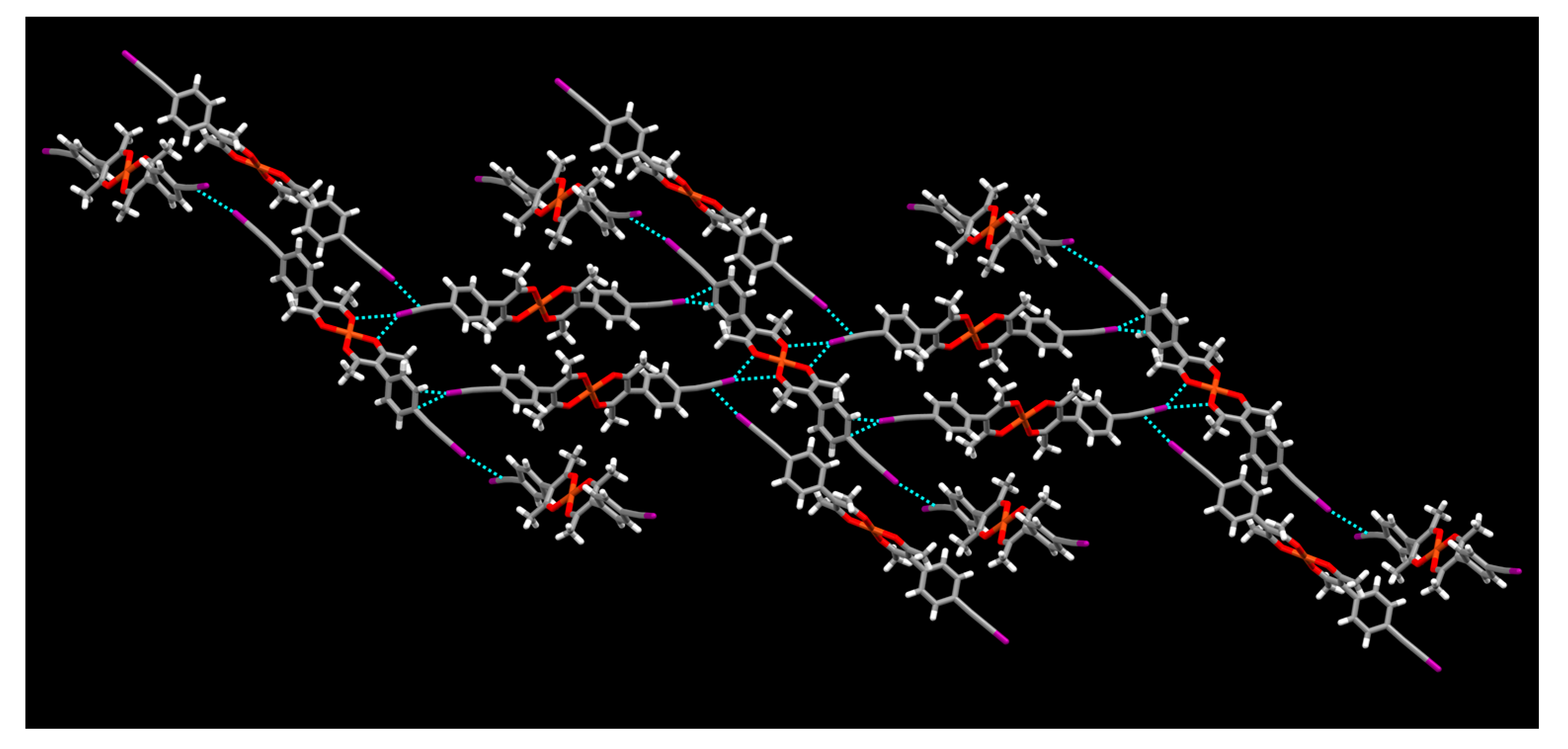
In addition, there is an another C-I⋯π interaction between an iodine atom and the aromatic ring r(I⋯centroid of phenyl ring) 3.58 Å, θ (C-I⋯centroid of phenyl ring) 170.86°, r(I⋯C=C) 3.29 Å r(I⋯C≡C-I) 3.48 Å. The combination of the different types of halogen bonds combine to produce a 3-D architecture in the structure of of [Cu(L3)2] (Figure 17).

3. Discussion

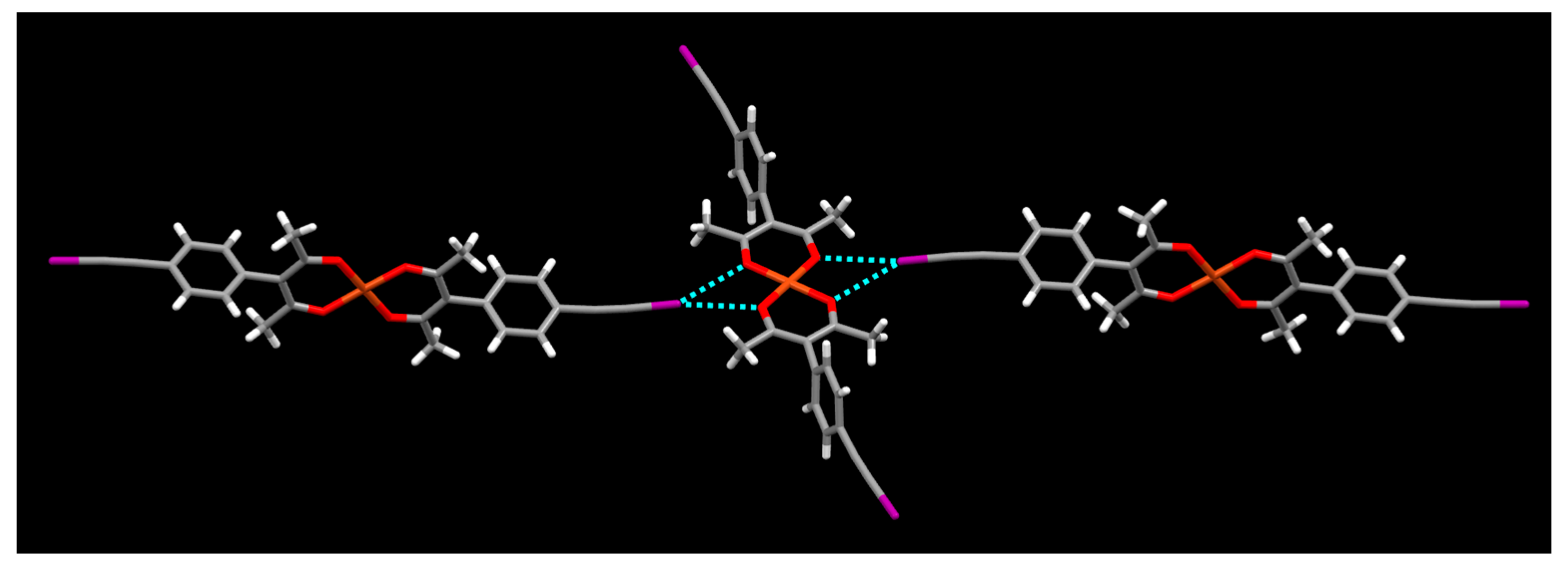
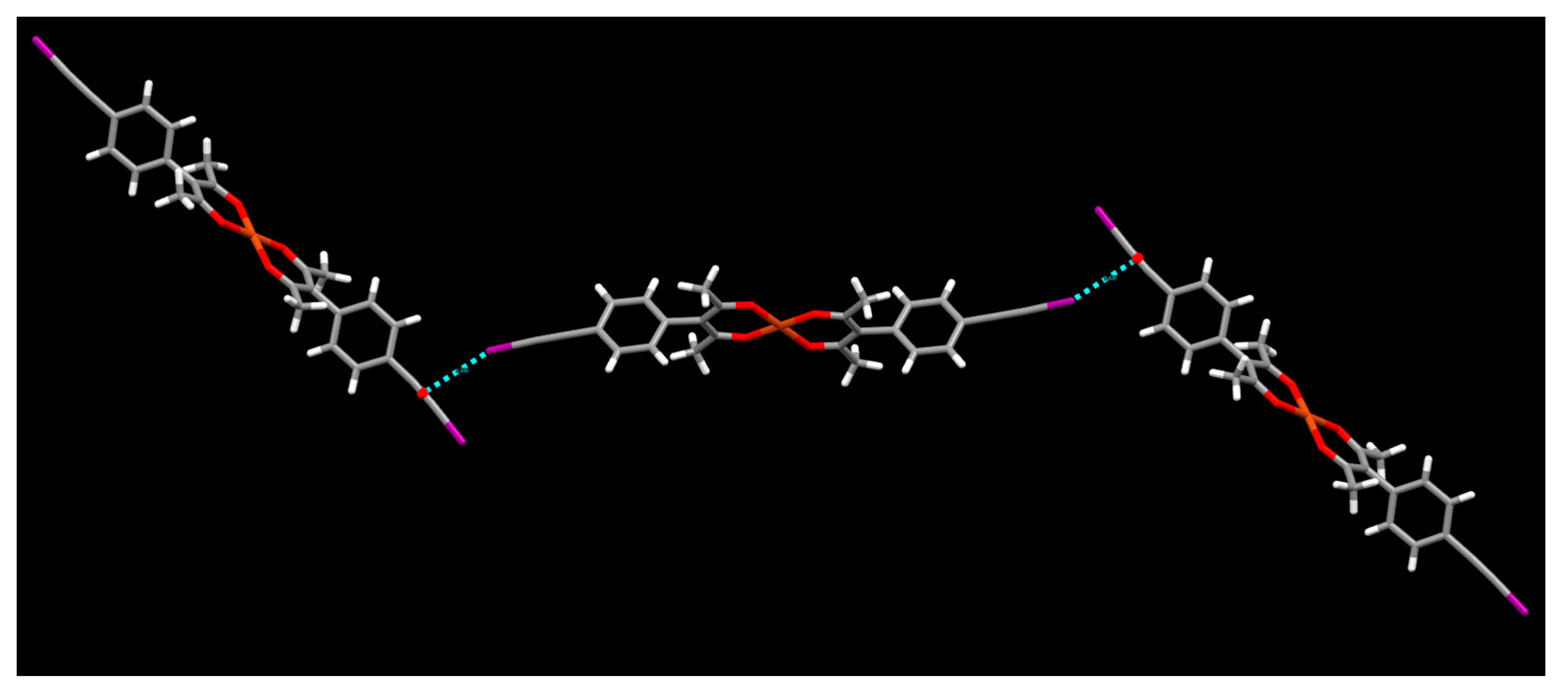
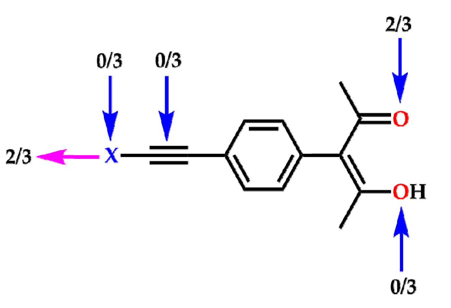
A common structural feature among all three ligands is the intramolecular hydroxyl⋯keto hydrogen bonding between the hydroxyl group and the oxygen of the keto group. However, only the iodo- and bromo substituted ligands, L3 and L2, show clear signs of halogen bonding in their crystal structures and, in both cases, the acceptor site is the oxygen atom of the keto group, which carries a higher negative charge than the enolic oxygen atom. Despite the activation through an adjacent ethynyl group, the chloro analogue does not show halogen bonding due to the absence of a substantive σ-hole and a correspondingly small positive electrostatic potential. Of the four postulated plausible halogen-bond acceptor sites, only one site was utilized in the three structures of the ligands themselves as summarized in Scheme 4.
Ligands L2 and L3 are isostructural indicating that both bromine and iodine are sufficiently activated by the adjacent ethyl group to provide halogen-bond interactions that have very similar structure-directing consequences (in this case they both produce infinite 1-D chains via C-X⋯O=C halogen bonds). Iodine is more polarizable than bromine which leads to a greater reduction in the combined van der Waals radii of X⋯O in L3, compared to that of L2.
When these ligands were combined with the divalent metal ion Cu(II), the expected complexes with a 1:2 metal ligand stoichiometry was afforded in all cases. The lack of halogen bonding in the crystal structure of L1 is carried over into the Cu(II) structures thereof, and again no notable short contacts involving the chloro substituent were present. In contrast, in the structures of metal complexes with L2 and L3, which are decorated with more polarizable bromo, and iodo substituents, respectively, halogen bonds become prevalent. All in all, in five of the seven structures of metal-ligand complexes a notable halogen bond could be observed. Solvent molecules capable of acting as appropriate electron-pair donors performed as halogen-bond acceptors in four cases, two different halogen-bond acceptors sites on the complex itself were utilized in one structure, Scheme 5.
In order to rationalize the involvement of acac oxygen atoms in halogen bonding, a simple Density Functional Theory (DFT) calculation was performed for Cu(L3)2 system. The results show that the HOMO orbitals of the complex are located around the acac oxygen atoms indicating their ability to act as partial electron donors in halogen bonding (Figure 18).
Iodine is, as expected, a better halogen-bond donor than bromine as indicated by higher van der Waals radii reduction of I⋯O bonds compared to Br⋯O bond in the structures [Cu(L3)2]·C4H8O2 and [Cu(L2)2]·C4H8O2 respectively. Further support for this can be inferred indirectly from the TGA data of the isostructural ethyl acetate solvates; the loss of the halogen bound solvent molecule occurred at 50 °C in [Cu(L2)2]·C4H8O2 whereas it was removed from the crystalline complex [Cu(L3)2]·C4H8O2 at 76 °C, which may reflect a stronger solvent⋯X-C bond in the latter case (Figures S1–S3).
All but one metal complex displays square-planar geometries; the one exception, [Cu(L3)2]·4CH3CN was octahedral due to the axial coordination of two acetonitrile molecules.
In the presence of weakly coordinating solvents such as nitromethane, halogen-solvent interactions are not observed. Activated iodine has shown the ability of forming interactions with the π-electron density of a triple bond which can act as a halogen bond acceptor [46,47,48]. In the complex [Cu(L3)2], mainly halogen⋯π interactions and halogen⋯oxygen interactions are observed due to the absence of a competitive halogen bond acceptor solvent. The structure propagates in a 3-D direction with halogen bonding and halogen⋯π interactions between halogen atom and triple bond-π cloud (Figure 17). In this 3D assembly, halogen⋯π interactions between the halogen atom and the π-electron cloud of the phenyl group also assist to hold the packing.
In addition to the halogen bonding interactions numerous C-H⋯O hydrogen bonds produced a very consistent structural feature, an infinite slipped stack, in six of the seven metal complexes. The exception being the octahedral [Cu(L3)2]·4CH3CN where steric hindrance caused by additional acetonitrile molecules prevents the formation of C-H⋯O hydrogen bonds.

4. Materials and Methods

All chemicals were purchased from commercial sources and used without further purifications. The syntheses of biacetyl-trimethyl phosphite (1:1) adduct, 1, was carried out according to a previously reported procedure [49].
1H-NMR and 13C-NMR spectra were recorded on a Varian Unity plus 400 MHz spectrometer (Varian, Inc.) in CDCl3. Melting points were determined on a Fisher-Johns melting point apparatus and are uncorrected. Infrared spectroscopy (IR) was done on a Nicolet 380 FT-IR (Thermo Scientific, Madison, WI, USA). DSC traces were obtained on a TA Q20 (TA instruments, New Castle, DE, USA). TGA traces were taken on a TA Q50 (TA instruments, New Castle, DE, USA).

4.1. Synthesis

Synthesis of 4-(trimethylsilylethynyl)benzaldehyde [42], 4-(bromoethynyl)benzaldehyde [50], and 4-(iodoethynyl)benzaldehyde [50] were carried out by using literature reported methods. Synthesis of 4-(chloroethynyl)benzaldehyde was carried out by using a modified literature method [50]. Synthesis of L1, L2 and L3 were carried out based on literature reported methods [37].

4.1.1. Synthesis of 4-(trimethylsilylethynyl)benzaldehyde

A stirred solution of 4.5 g (19.40 mmol) 4-bromobenzaldehyde, 83 mg (0.46 mmol) of CuI, and 163 mg (0.23 mmol) of Pd(PPh3)2Cl2 in 80 mL of trimethylamine was degassed with N2 for 20 min. A solution of 2.28 g (23.28 mmol) of trimethylsilylacetylene was added to the stirred solution. The mixture was heated under reflux overnight under N2. Upon completion of the reaction the solvent was evaporated by rotavap. The residue was dissolved in ethyl acetate and washed three times with water followed by a saturated NaCl solution. The organic layer was dried with MgSO4 and the solvent was evaporated by rotavap. The residue was chromatographed on a silica column with hexanes as the eluent to obtain the pure product. Yield: 4.08 g (93%); m.p. 59–61 °C (Lit, 57–58 °C [42]); 1H-NMR (δH, CDCl3, 400 MHz): 10.01 (1H, s), 7.83 (2H, d), 7.61 (2H, d), 0.28 (9H, s).

4.1.2. Synthesis of 4-(chloroethynyl)benzaldehyde

In 60 mL of acetonitrile, 2.0 g (9.8 mmol) of 4-(trimethylsilylethynyl)benzaldehyde and 1.86 g (14.6 mmol) of AgF were dissolved and degassed with N2 for 20 min. 1.94 g (14.6 mmol) of N-chlorosuccinimide was added to the stirred solution and the reaction vessel was covered with aluminum foil. The reaction mixture was stirred under N2 at room temperature overnight. Upon completion of the reaction, the mixture was passed through a short pad of silica. The solvent was evaporated and the residue was dissolved in diethyl ether and washed three times with water. The organic layer was dried over MgSO4 and the solvent was evaporated to get the pure product. Yield: 1.10 g (67%); m.p. 77–80 °C; 1H-NMR (δH, CDCl3, 400 MHz): 10.01 (1H, s), 7.83 (2H, d), 7.59 (2H, d).

4.1.3. Synthesis of 4-(bromoethynyl)benzaldehyde

In 50 mL of acetonitrile, 1.5 g (7.4 mmol) of 4-(trimethylsilylethynyl)benzaldehyde and 940 mg of AgF (7.4 mmol) were dissolved and degassed with N2 for 20 min. 1.32 g (7.42 mmol) of N-bromosuccinimide was added to the stirred solution and the reaction vessel was covered with aluminum foil. The reaction mixture was stirred under N2 at room temperature 5 h. Upon completion of the reaction, the mixture was passed through a short pad of silica. The solvent was evaporated and the residue was dissolved in diethyl ether and washed three times with water. The organic layer was dried over MgSO4 and the solvent was evaporated to get the pure product. Yield: 1.49 g (96%); m.p. 99–102 °C (Lit, 96–98 °C [51]); 1H-NMR (δH, CDCl3, 400 MHz): 10.02 (1H, s), 7.84 (2H, d), 7.61 (2H, d).

4.1.4. Synthesis of 4-(iodoethynyl)benzaldehyde

4-(Iodoethynyl)benzaldehyde was prepared according to the preparation of 4-(bromoethynyl)benzaldehyde from 1.5 g (7.4 mmol) of 4-(trimethylsilylethinyl)benzaldehyde, 940 mg (7.4 mmol) of AgF and 1.67 g of N-iodosuccinimide (7.42 mmol) in 50 mL of acetonitrile. Yield: 1.86 g (98%); m.p.141–143 °C (Lit, 120–121 °C [52]); 1H-NMR (δH, CDCl3, 400 MHz): 10.02 (1H, s), 7.84 (2H, d), 7.59 (2H, d).

4.1.5. Synthesis of 3-(4-(chloroethynyl)phenyl)-4-Hydroxypent-3-en-2-one, L1

4-(Chloroethynyl)benzaldehyde (1.0 g, 6.0 mmol) was placed in a 100 mL round bottom flask under a N2 atmosphere. 1 (1.53 g, 7.3 mmol) was added to the flask with continuous stirring. The resulting slurry was stirred for 24 h at room temperature under a N2 atmosphere to obtain an oil. Then 50 mL of methanol was added and the mixture was heated under reflux overnight under a N2 atmosphere. Upon cooling the solution to room temperature, methanol was evaporated by rotavap to obtain a yellow oil. The residue was dissolved in 50 mL methanol and cooled to −78 °C to yield a white crystalline solid. The precipitate was filtered and washed with cold methanol to obtain the pure product. Colourless prism-shaped crystals suitable for single-crystal X-ray diffraction were grown using slow evaporation from methanol. Yield: 0.57 g (40%); m.p. 139–141 °C; 1H-NMR (δH, CDCl3, 400 MHz): 16.68 (1H, s), 7.47 (2H, d), 7.14 (2H, d), 1.89 (6H, s); 13C-NMR (δc, CDCl3, 400 MHz) 190.72, 137.37, 132.40, 131.19, 121.44, 114.59, 68.93, 68.70, 24.13.

4.1.6. Synthesis of 3-(4-(bromoethynyl)phenyl)-4-Hydroxypent-3-en-2-one, L2

3-(4-(Bromoethynyl)phenyl)-4-hydroxypent-3-en-2-one was prepared according to the preparation of 3-(4-(chloroethynyl)phenyl)-4-hydroxypent-3-en-2-one from 1.0 g (4.8 mmol) of 4-(bromoethynyl)benzaldehyde and 1.2 g (5.8 mmol) of 1. Brown color prism-shaped crystals suitable for single-crystal X-ray diffraction were grown using slow evaporation from methanol. Yield: 0.72 g (56%); m.p. 155–158 °C; 1H-NMR (δH, CDCl3, 400 MHz): 1H-NMR (δH, CDCL3, 400 MHz): 16.67 (1H, s), 7.48 (2H, d), 7.14 (2H, d), 1.89 (6H, s); 13C-NMR (δc, CDCl3, 400 MHz) 190.70, 137.46, 132.43, 131.16, 121.98, 114.59, 79.58, 50.50, 24.13.

4.1.7. Synthesis of 3-(4-(iodoethynyl)phenyl)-4-Hydroxypent-3-en-2-one, L3

3-(4-(Iodoethynyl)phenyl)-4-hydroxypent-3-en-2-one was prepared according to the preparation of 3-(4-(chloroethynyl)phenyl)-4-hydroxypent-3-en-2-one from 1.0 g (3.9 mmol) of 4-(chlorooethynyl)benzaldehyde and 0.98 g (4.7 mmol) of 1. Yellow color plate-shaped crystals suitable for single-crystal X-ray diffraction were grown using slow evaporation from methanol. Yield: 0.65 g (51%); m.p. 164–167 °C 1H-NMR (δH, CDCl3, 400 MHz): 16.67 (1H, s), 7.47 (2H, d), 7.14 (2H, d), 1.88 (6H, s); 13C-NMR (δc, CDCl3, 400 MHz) 190.72, 137.58, 132.76, 131.05, 122.66, 114.59, 93.64, 24.13.

4.1.8. Synthesis of [Cu(L1)2]

L1 (0.010 g) was dissolved in 1.0 mL of acetonitrile and a drop of triethylamine was added to the solution in a vial and stirred well. Then 0.006 g of copper(II) tetrafluoroborate hydrate in 1.0 mL of acetonitrile was added. The solution was mixed well and kept for slow evaporation at room temperature. After two days, green needle-shaped crystals were obtained and subjected to single-crystal X-ray diffraction. Dec. 309 °C (DSC 5 °C/min).

4.1.9. Synthesis of [Cu(L2)2]·2CH3CN

L2 (0.010 g) was dissolved in 1.0 mL of acetonitrile and a drop of triethylamine was added in a vial and stirred well. Then 0.005 g of copper(II) tetrafluoroborate hydrate in 1.0 mL of acetonitrile was added to the above mixture. The resulting mixture was mixed well and kept for slow evaporation at room temperature. After one day green plate-shaped crystals were obtained and subjected to single-crystal X-ray diffraction. Dec. 276 °C (DSC 5 °C/min).

4.1.10. Synthesis of [Cu(L2)2]·2C4H8O2

L2 (0.010 g) was dissolved in 1.0 mL of ethyl acetate and a drop of triethylamine was added in a vial and stirred well. Then 0.005 g of copper(II) tetrafluoroborate hydrate in 1.0 mL of ethyl acetate was added to the above mixture. The resulting solution was mixed well and kept for slow evaporation at room temperature. After one day blue prism-shaped crystals were obtained and subjected to single-crystal X-ray diffraction (Bruker, Madison, WI, USA). Dec. 263 °C (DSC 5 °C/min).

4.1.11. Synthesis of [Cu(L2)2]·2CH3NO2

L2 (0.010 g) was dissolved in 1.0 mL of nitromethane and a drop of triethylamine was added in a vial and stirred well. Then 0.005 g of copper(II) tetrafluoroborate hydrate in 1.0 mL of nitromethane was added to the above mixture. The resulting solution was mixed well and kept for slow evaporation at room temperature. After two days green plate-shaped crystals were obtained and subjected to the single-crystal X-ray diffraction. Dec. 274 °C (DSC 5 °C/min).

4.1.12. Synthesis of [Cu(L3)2]·4CH3CN

L3 (0.010 g) was dissolved in 1.0 mL of acetonitrile and a drop of triethylamine was added in a vial and stirred well. Then 0.004 g of copper(II) tetrafluoroborate hydrate in 1.0 mL of acetonitrile was added to the above mixture. The resulting solution was mixed well and kept for slow evaporation at room temperature. After one day blue plate-shaped crystals were obtained and subjected to single-crystal X-ray diffraction. Dec. 182 °C (DSC 5 °C/min).

4.1.13. Synthesis of [Cu(L3)2]·2C4H8O2

L3 (0.010 g) was dissolved in 1.0 mL of ethyl acetate and a drop of triethylamine was added to in a vial and stirred well. Then 0.004 g of copper(II) tetrafluoroborate hydrate in 1.0 mL of ethyl acetate was added to the above mixture. The resulting solution was mixed well and kept for slow evaporation at room temperature. After one day green needle-shaped crystals were obtained and subjected to single-crystal X-ray diffraction. Dec. 205 °C (DSC 5 °C/min).

4.1.14. Synthesis of [Cu(L3)2]

L3 (0.010 g) was dissolved in 1.0 mL of nitromethane and a drop of triethylamine was added in a vial and stirred well. Then 0.004 g of copper(II) tetrafluoroborate hydrate in 1.0 mL of nitromethane was added to the above mixture. The resulting solution was mixed well and kept for slow evaporation at room temperature. After three days green needle-shaped crystals were obtained and subjected to single-crystal X-ray diffraction. Dec. 180 °C (DSC 5 °C/min).

4.2. X-ray Crystallography

Datasets were collected on a Bruker Kappa APEX II system using MoKα radiation (L1; L2; [Cu(L1)2]; [Cu(L2)2]·2CH3CN; [Cu(L2)2]·2C4H8O2; [Cu(L2)2]·2CH3NO2; [Cu(L3)2]·4CH3CN; [Cu(L3)2].2C4H8O2; [Cu(L3)2]). Data were collected using APEX2 software [53]. Initial cell constants were found by small widely separated “matrix” runs. Data collection strategies were determined using COSMO [54]. Scan speed and scan widths were chosen based on scattering power and peak rocking curves. Datasets were collected at −143 °C ([Cu(L1)2]; [Cu(L3)2]·2C4H8O2; [Cu(L3)2]), and at −153 °C (L1; L2; [Cu(L2)2]·2CH3CN; [Cu(L2)2]·2C4H8O2; [Cu(L2)2]·2CH3NO2; [Cu(L3)2]·4CH3CN) using an Oxford Cryostream low-temperature device (Table S1).
For the above datasets, unit cell constants and orientation matrix were improved by least-squares refinement of reflections thresholded from the entire dataset. Integration was performed with SAINT [55], using this improved unit cell as a starting point. Precise unit cell constants were calculated in SAINT from the final merged dataset. Lorenz and polarization corrections were applied. Multi-scan absorption corrections were performed with SADABS [56].
For the above datasets, data were reduced with SHELXTL [57]. The structures were solved in all cases by direct methods without incident. Except as noted, hydrogen atoms were located in idealized positions and were treated with a riding model. All non-hydrogen atoms were assigned anisotropic thermal parameters. Refinements continued to convergence, using the recommended weighting schemes.
Also, the dataset for L3 was collected on an Oxford Diffraction Xcalibur four-circle kappa geometry single-crystal diffractometer with Sapphire 3 CCD detector, using a graphite monochromated MoKα radiation, and applying the CrysAlisPro Software system [58] at 23 °C.
Data reduction, including Lorentz and polarization corrections as well as absorption correction, was done by the CrysAlis RED program [58]. The structures were solved by direct methods implemented in the SHELXS-2013 program [59]. The coordinates and the anisotropic displacement parameters for all non-hydrogen atoms were refined by the full-matrix least-squares methods based on F2 using the SHELXL-2013 program [59]. Except as noted, hydrogen atoms were located in idealized positions and were treated with a riding model.
[Cu(L3)2]·4CH3CN—The asymmetric unit contains two molecules of the iodoethynyl ligand complexed with a Cu(II) atom and four acetonitrile solvent molecules. One of the acetonitrile solvent molecules is disordered over two closely related positions, thus representing different orientations. Relative populations were allowed to refine. Thermal parameters for closely located atoms were pairwise constrained using EADP commands. Geometry of the acetonitrile solvent molecule was restrained using the SAME command.
[Cu(L2)2]·2CH3NO2—The asymmetric unit contains two molecules of the bromoethynyl ligand complexed with a Cu(II) atom and two molecules of nitromethane solvent. One of the methyl groups on the acetylacetonate moiety is disordered over two closely related positions, thus representing different orientations. Relative positions were allowed to refine. Thermal parameters for closely located methyl carbon atoms were pairwise constrained using the EADP command.
Also, one of the nitromethane solvent molecules is disordered over two closely related positions, thus representing different orientations. Relative populations were allowed to refine. Thermal parameters for closely located atoms were pairwise constrained using EADP commands. The geometry of the nitromethane solvent molecule was restrained using the SAME command. Also, all atoms of the nitromethane solvent molecule were restrained to lie in a common plane using the FLAT command.
L1—Coordinates of the acetylacetonate moiety proton H12 were allowed to refine.
L3—Coordinates of the acetylacetonate moiety proton H10 were allowed to refine.

5. Conclusions

We showed that two of three new ligands capable of simultaneous metal-chelation and directional halogen bonding presented herein, have considerable potential as building blocks of extended 2-D and 3-D architectures. The work completed so far has allowed us to define some key parameters that need to be considered when devising practical reaction schemes for the next stage in this process. We demonstrated that the bromo- and iodo substituted ligands are capable of forming halogen bonds with several different solvent molecules that are capable of acting as halogen-bond acceptors such as acetonitrile and ethyl acetate. Consequently, if we want to synthesize robust extended architectures by combining L2 or L3 with bridging linkers (such as 4,4′-bipyridine or pyrazine), we need to avoid solvents that can compete with the intended halogen bonds and possibly disrupt the desired ligand⋯linker interactions. These ligands are likely to be particularly useful as construction elements for several extended networks of a variety of controllable topologies and metrics since the acac-moiety is unlikely to be displaced by a non-chelating ligand. Therefore we can reliable use the metal node as an anchoring point for axially bound ligands (with metal ions that support an octahedral geometry) whilst utilizing the bromo- or iodoethynyl species in halogen bonds that are perpendicular to the metal⋯axial ligand direction. We are currently exploring such a strategy in a systematic structural examination with a variety of metal ions and bridging linkers.

Supplementary Materials

The following are available online at www.mdpi.com/2073-4352/7/7/226/s1, Scheme S1. Synthesis pathway to ligands L1L3, Figure S1. TGA trace of [Cu(L2)2]·2C4H8O2, Figure S2. TGA trace of [Cu(L3)2]·2C4H8O2, Figure S3. TGA traces comparison, [Cu(L2)2]·2C4H8O2 and [Cu(L3)2]·2C4H8O2 with Cu(L1)2, Table S1: Crystallographic data for the ligands and their metal complexes. Cif files deposited with the CCDC, 1557430-1557439.

Acknowledgments

We are grateful for financial support from NSF (CHE-0957607). Marijana Ðaković acknowledges support from the Croatian Science Foundation under the project UIP-11-2013-1809.

Author Contributions

Janaka C. Gamekkanda performed the experiments; Janaka C. Gamekkanda and Christer B. Aakeröy analyzed the data and wrote the paper; Abhijeet S. Sinha, Marijana Ðaković and John Desper carried out the crystallography.

Conflicts of Interest

The authors declare no conflict of interest. The founding sponsors had no role in the design of the study; in the collection, analyses, or interpretation of data; in the writing of the manuscript, and in the decision to publish the results.

References

  1. Aakeröy, C.B.; Desper, J.; Smith, M.M. Constructing, deconstructing, and reconstructing ternary supermolecules. Chem. Commun. 2007, 3936–3938. [Google Scholar] [CrossRef] [PubMed]
  2. Amombo Noa, F.M.; Bourne, S.A.; Su, H.; Weber, E.; Nassimbeni, L.R. Hydrogen bonding versus halogen bonding in host–guest compounds. Cryst. Growth Des. 2016, 16, 4765–4771. [Google Scholar] [CrossRef]
  3. Gawade, R.L.; Chakravarty, D.K.; Kotmale, A.; Sangtani, E.; Joshi, P.V.; Ahmed, A.; Mane, M.V.; Das, S.; Vanka, K.; Rajamohanan, P.R.; et al. Additive mediated syn-anti conformational tuning at nucleation to capture elusive polymorphs: Remarkable role of extended π-stacking interactions in driving the self-assembly. Cryst. Growth Des. 2016, 16, 2416–2428. [Google Scholar] [CrossRef]
  4. Aakeröy, C.B.; Wijethunga, T.K.; Desper, J. Constructing molecular polygons using halogen bonding and bifurcated n-oxides. CrystEngComm 2014, 16, 28–31. [Google Scholar] [CrossRef]
  5. Bauza, A.; Quinonero, D.; Deya, P.M.; Frontera, A. Halogen bonding versus chalcogen and pnicogen bonding: A combined cambridge structural database and theoretical study. CrystEngComm 2013, 15, 3137–3144. [Google Scholar] [CrossRef]
  6. Takemura, A.; McAllister, L.J.; Karadakov, P.B.; Pridmore, N.E.; Whitwood, A.C.; Bruce, D.W. Competition and cooperation: Hydrogen and halogen bonding in co-crystals involving 4-iodotetrafluorobenzoic acid, 4-iodotetrafluorophenol and 4-bromotetrafluorophenol. CrystEngComm 2014, 16, 4254–4264. [Google Scholar] [CrossRef]
  7. Maugeri, L.; Lébl, T.; Cordes, D.B.; Slawin, A.M.Z.; Philp, D. Cooperative binding in a phosphine oxide-based halogen bonded dimer drives supramolecular oligomerization. J. Org. Chem. 2017, 82, 1986–1995. [Google Scholar] [CrossRef] [PubMed]
  8. Kukovec, B.M.; Malik, M.; Kodrin, I.; Aakeröy, C.B.; Đaković, M. Directed assembly of acac-based complexes by deliberately fine-tuning electrostatic molecular-recognition events. Cryst. Growth Des. 2016, 16, 7308–7317. [Google Scholar] [CrossRef]
  9. Bauza, A.; Frontera, A. Supramolecular nanotubes based on halogen bonding interactions: Cooperativity and interaction with small guests. Phys. Chem. Chem. Phys. 2017, 19, 12936–12941. [Google Scholar] [CrossRef] [PubMed]
  10. Pizzi, A.; Lascialfari, L.; Demitri, N.; Bertolani, A.; Maiolo, D.; Carretti, E.; Metrangolo, P. Halogen bonding modulates hydrogel formation from fmoc amino acids. CrystEngComm 2017, 19, 1870–1874. [Google Scholar] [CrossRef]
  11. Béziau, A.; Baudron, S.A.; Rogez, G.; Hosseini, M.W. Assembly, disassembly, and reassembly: Conversion of homometallic coordination networks into mixed metal–organic frameworks. Inorg. Chem. 2015, 54, 2032–2039. [Google Scholar] [CrossRef] [PubMed]
  12. Durá, G.; Carrión, M.C.; Jalón, F.A.; Manzano, B.R.; Rodríguez, A.M.; Mereiter, K. Robust 2d coordination networks from a two-step assembly process with predesigned silver cyclic dimers and hexamethylenetetramine. Cryst. Growth Des. 2015, 15, 3321–3331. [Google Scholar] [CrossRef]
  13. Durá, G.; Carrión, M.C.; Jalón, F.A.; Manzano, B.R.; Rodríguez, A.M. Formation of mono-, di- and trinuclear species in the self-assembly of Bis(pyraz-olyl)(pyridin-3-yl)methane ligands and metals with different coordination geometries. Eur. J. Inorg. Chem. 2015, 2015, 5874–5885. [Google Scholar] [CrossRef]
  14. He, L.; Ma, D.; Duan, L.; Wei, Y.; Qiao, J.; Zhang, D.; Dong, G.; Wang, L.; Qiu, Y. Control of intramolecular π–π stacking interaction in cationic iridium complexes via fluorination of pendant phenyl rings. Inorg. Chem. 2012, 51, 4502–4510. [Google Scholar] [CrossRef] [PubMed]
  15. Khavasi, H.R.; Kavand, S. [small pi]-stacking synthon repetitivity in coordination compounds. CrystEngComm 2016, 18, 4760–4764. [Google Scholar] [CrossRef]
  16. Choudhury, S.R.; Dey, B.; Das, S.; Gamez, P.; Robertazzi, A.; Chan, K.-T.; Lee, H.M.; Mukhopadhyay, S. Supramolecular lone pair-π/π-π/π-anion assembly in a Mg(II)-malonate-2-aminopyridine-nitrate ternary system. J. Phys. Chem. A 2009, 113, 1623–1627. [Google Scholar] [CrossRef] [PubMed]
  17. Kumari, H.; Jin, P.; Teat, S.J.; Barnes, C.L.; Dalgarno, S.J.; Atwood, J.L. Strong cation⋯π interactions promote the capture of metal ions within metal-seamed nanocapsule. J. Am. Chem. Soc. 2014, 136, 17002–17005. [Google Scholar] [CrossRef] [PubMed]
  18. Safin, D.A.; Robeyns, K.; Babashkina, M.G.; Vande Velde, C.M.L.; Filinchuk, Y. Ligand-driven anion-π interaction-induced silver(i) coordination chemistry. Cryst. Growth Des. 2016, 16, 3763–3770. [Google Scholar] [CrossRef]
  19. Manna, P.; Seth, S.K.; Das, A.; Hemming, J.; Prendergast, R.; Helliwell, M.; Choudhury, S.R.; Frontera, A.; Mukhopadhyay, S. Anion induced formation of supramolecular associations involving lone pair-π and anion-π interactions in Co(II) malonate complexes: Experimental observations, hirshfeld surface analyses and dft studies. Inorg. Chem. 2012, 51, 3557–3571. [Google Scholar] [CrossRef] [PubMed]
  20. Seth, S.K.; Saha, I.; Estarellas, C.; Frontera, A.; Kar, T.; Mukhopadhyay, S. Supramolecular self-assembly of m-ida complexes involving lone-pair⋯π interactions: Crystal structures, hirshfeld surface analysis, and DFT calculations [H2IDA = iminodiacetic acid, M = Cu(II), Ni(II)]. Cryst. Growth Des. 2011, 11, 3250–3265. [Google Scholar] [CrossRef]
  21. Tiekink, E.R.T.; Zukerman-Schpector, J. Gold[three dots, centered][small pi] aryl interactions as supramolecular synthons. CrystEngComm 2009, 11, 1176–1186. [Google Scholar] [CrossRef]
  22. Cheng, B.; Tehrani, A.A.; Hu, M.-L.; Morsali, A. Supramolecular assemblies of Ru(II) organometallic half-sandwich complexes. CrystEngComm 2014, 16, 9125–9134. [Google Scholar] [CrossRef]
  23. Dong, H.; Wang, D.; Sun, G.; Hinestroza, J.P. Assembly of metal nanoparticles on electrospun nylon 6 nanofibers by control of interfacial hydrogen-bonding interactions. Chem. Mater. 2008, 20, 6627–6632. [Google Scholar] [CrossRef]
  24. Piñón, V.; Weck, M. Patterned polymeric multilayered assemblies through hydrogen bonding and metal coordination. Langmuir 2012, 28, 3279–3284. [Google Scholar] [CrossRef] [PubMed]
  25. Marshall, L.J.; de Mendoza, J. Self-assembled squares and triangles by simultaneous hydrogen bonding and metal coordination. Org. Lett. 2013, 15, 1548–1551. [Google Scholar] [CrossRef] [PubMed]
  26. Sommer, S.K.; Zakharov, L.N.; Pluth, M.D. Design, synthesis, and characterization of hybrid Metal-Ligand Hydrogen-Bonded (MLHB) supramolecular architectures. Inorg. Chem. 2015, 54, 1912–1918. [Google Scholar] [CrossRef] [PubMed]
  27. Wang, L.; Zhu, L.; Yin, P.; Fu, W.; Chen, J.; Hao, J.; Xiao, F.; Lv, C.; Zhang, J.; Shi, L.; et al. From 0 d dimer to 2 d network—Supramolecular assembly of organic derivatized polyoxometalates with remote hydroxyl via hydrogen bonding. Inorg. Chem. 2009, 48, 9222–9235. [Google Scholar] [CrossRef] [PubMed]
  28. Cavallo, G.; Metrangolo, P.; Milani, R.; Pilati, T.; Priimagi, A.; Resnati, G.; Terraneo, G. The halogen bond. Chem. Rev. 2016, 116, 2478–2601. [Google Scholar] [CrossRef] [PubMed] [Green Version]
  29. Priimagi, A.; Cavallo, G.; Metrangolo, P.; Resnati, G. The halogen bond in the design of functional supramolecular materials: Recent advances. Acc. Chem. Res. 2013, 46, 2686–2695. [Google Scholar] [CrossRef] [PubMed] [Green Version]
  30. Desiraju Gautam, R.; Ho, P.S.; Kloo, L.; Legon Anthony, C.; Marquardt, R.; Metrangolo, P.; Politzer, P.; Resnati, G.; Rissanen, K. Definition of the halogen bond (IUPAC recommendations 2013). Pure Appl. Chem. 2013, 85, 1711. [Google Scholar] [CrossRef]
  31. Meyer, F.; Dubois, P. Halogen bonding at work: Recent applications in synthetic chemistry and materials science. CrystEngComm 2013, 15, 3058–3071. [Google Scholar] [CrossRef]
  32. Berger, G.; Soubhye, J.; Meyer, F. Halogen bonding in polymer science: From crystal engineering to functional supramolecular polymers and materials. Polym. Chem. 2015, 6, 3559–3580. [Google Scholar] [CrossRef]
  33. Ivanov, D.M.; Novikov, A.S.; Ananyev, I.V.; Kirina, Y.V.; Kukushkin, V.Y. Halogen bonding between metal centers and halocarbons. Chem. Commun. 2016, 52, 5565–5568. [Google Scholar] [CrossRef] [PubMed]
  34. Khavasi, H.R.; Ghanbarpour, A.; Tehrani, A.A. The role of intermolecular interactions involving halogens in the supramolecular architecture of a series of Mn(II) coordination compounds. RSC Adv. 2016, 6, 2422–2430. [Google Scholar] [CrossRef]
  35. Bertani, R.; Sgarbossa, P.; Venzo, A.; Lelj, F.; Amati, M.; Resnati, G.; Pilati, T.; Metrangolo, P.; Terraneo, G. Halogen bonding in metal–organic–supramolecular networks. Coord. Chem. Rev. 2010, 254, 677–695. [Google Scholar] [CrossRef]
  36. Li, B.; Zang, S.-Q.; Wang, L.-Y.; Mak, T.C.W. Halogen bonding: A powerful, emerging tool for constructing high-dimensional metal-containing supramolecular networks. Coord. Chem. Rev. 2016, 308, 1–21. [Google Scholar] [CrossRef]
  37. Aakeröy, C.B.; Sinha, A.S.; Chopade, P.D.; Desper, J. Halogen bonding or close packing? Examining the structural landscape in a series of Cu(II)-acac complexes. Dalton Trans. 2011, 40, 12160–12168. [Google Scholar] [CrossRef] [PubMed]
  38. Clark, T.; Hennemann, M.; Murray, J.S.; Politzer, P. Halogen bonding: The σ-hole. J. Mol. Model. 2007, 13, 291–296. [Google Scholar] [CrossRef] [PubMed]
  39. Riley, K.E.; Murray, J.S.; Fanfrlík, J.; Řezáč, J.; Solá, R.J.; Concha, M.C.; Ramos, F.M.; Politzer, P. Halogen bond tunability i: The effects of aromatic fluorine substitution on the strengths of halogen-bonding interactions involving chlorine, bromine, and iodine. J. Mol. Model. 2011, 17, 3309–3318. [Google Scholar] [CrossRef] [PubMed]
  40. Aakeröy, C.B.; Wijethunga, T.K.; Desper, J. Practical crystal engineering using halogen bonding: A hierarchy based on calculated molecular electrostatic potential surfaces. J. Mol. Struct. 2014, 1072, 20–27. [Google Scholar] [CrossRef]
  41. Nguyen, S.T.; Rheingold, A.L.; Tschumper, G.S.; Watkins, D.L. Elucidating the effects of fluoro and nitro substituents on halogen bond driven assemblies of pyridyl-capped π-conjugated molecules. Cryst. Growth Des. 2016, 16, 6648–6653. [Google Scholar] [CrossRef]
  42. Aakeröy, C.B.; Baldrighi, M.; Desper, J.; Metrangolo, P.; Resnati, G. Supramolecular hierarchy among halogen-bond donors. Chem. A Eur. J. 2013, 19, 16240–16247. [Google Scholar] [CrossRef] [PubMed] [Green Version]
  43. Carlucci, L.; Gavezzotti, A. A quantitative measure of halogen bond activation in cocrystallization. Phys. Chem. Chem. Phy. 2017. [Google Scholar] [CrossRef] [PubMed]
  44. Thalladi, V.R.; Goud, B.S.; Hoy, V.J.; Allen, F.H.; Howard, J.A.K.; Desiraju, G.R. Supramolecular synthons in crystal engineering. Structure simplification, synthon robustness and supramolecular retrosynthesis. Chem. Commun. 1996, 3, 401–402. [Google Scholar] [CrossRef]
  45. Desiraju, G.R. Designer crystals: Intermolecular interactions, network structures and supramolecular synthons. Chem. Commun. 1997, 16, 1475–1482. [Google Scholar] [CrossRef]
  46. Dumele, O.; Wu, D.; Trapp, N.; Goroff, N.; Diederich, F. Halogen bonding of (iodoethynyl)benzene derivatives in solution. Org. Lett. 2014, 16, 4722–4725. [Google Scholar] [CrossRef] [PubMed]
  47. Baldrighi, M.; Bartesaghi, D.; Cavallo, G.; Chierotti, M.R.; Gobetto, R.; Metrangolo, P.; Pilati, T.; Resnati, G.; Terraneo, G. Polymorphs and co-crystals of haloprogin: An antifungal agent. CrystEngComm 2014, 16, 5897–5904. [Google Scholar] [CrossRef]
  48. Aakeröy, C.B.; Welideniya, D.; Desper, J. Ethynyl hydrogen bonds and iodoethynyl halogen bonds: A case of synthon mimicry. CrystEngComm 2017, 19, 11–13. [Google Scholar] [CrossRef]
  49. Ramirez, F.; Patwardhan, A.V.; Ramanathan, N.; Desai, N.B.; Greco, C.V.; Heller, S.R. A new synthesis of α,β-dihydroxy ketones via oxyphosphoranes. Condensation of aliphatic α-diketones with aldehydes by means of trialkyl phosphites. P31 and H1 nuclear magnetic resonance spectra1,2. J. Am. Chem. Soc. 1965, 87, 543–548. [Google Scholar] [CrossRef]
  50. Osowska, K.; Lis, T.; Szafert, S. Protection/deprotection-free syntheses and structural analysis of (keto-aryl)diynes. Eur. J. Org. Chem. 2008, 2008, 4598–4606. [Google Scholar] [CrossRef]
  51. Aakeroy, C.B.; Sinha, A.S.; Epa, K.N.; Spartz, C.L.; Desper, J. A versatile and green mechanochemical route for aldehyde-oxime conversions. Chem. Commun. 2012, 48, 11289–11291. [Google Scholar] [CrossRef] [PubMed]
  52. Dumele, O.; Schreib, B.; Warzok, U.; Trapp, N.; Schalley, C.A.; Diederich, F. Halogen-bonded supramolecular capsules in the solid state, in solution, and in the gas phase. Angew. Chem. Int. Ed. 2017, 56, 1152–1157. [Google Scholar] [CrossRef] [PubMed]
  53. Bruker. APEX2 v2013.10-0, © 2013, Bruker Analytical X-ray Systems; Bruker: Madison, WI, USA, 2013. [Google Scholar]
  54. Bruker. COSMO v1.61, © 1999–2009, Bruker Analytical X-ray Systems; Bruker: Madison, WI, USA, 1999. [Google Scholar]
  55. Bruker. SAINT v8.34a, © 1997–2013, Bruker Analytical X-ray Systems; Bruker: Madison, WI, USA, 1997. [Google Scholar]
  56. Bruker. SADABS v2012/1, © 2012, Bruker Analytical X-ray Systems; Bruker: Madison, WI, USA, 2012. [Google Scholar]
  57. Bruker. SHELXTL v2008/4, © 2008, Bruker Analytical X-ray Systems; Bruker: Madison, WI, USA, 2008. [Google Scholar]
  58. Oxford Diffraction Ltd. Oxford Diffraction, Xcalibur CCD System, CrysAlis Software System, Version 171.31; Oxford Diffraction Ltd.: Oxford, UK, 2004. [Google Scholar]
  59. Sheldrick, G. A short history of shelx. Acta Crystallogr. Sect. A 2008, 64, 112–122. [Google Scholar] [CrossRef] [PubMed]
Scheme 1. Chelation of metal ions by β-diketones (acac) ligand.
Crystals 07 00226 sch001
Scheme 2. Three molecules that can act as chelating ligands (through the acac site) decorated with “activated” halogen-bond donors.
Crystals 07 00226 sch002
Scheme 3. Possible halogen–bond acceptor sites; (a) ligand itself, (b) metal ligand complex.
Crystals 07 00226 sch003
Figure 1. Part of the crystal structure of L1 (color codes: red—oxygen; green—chlorine).
Crystals 07 00226 g001
Figure 2. Part of the crystal structure of L2 (color codes: red—oxygen; gold—bromine).
Crystals 07 00226 g002
Figure 3. Part of the crystal structure of L3 (color codes: red—oxygen; purple—iodine).
Crystals 07 00226 g003
Figure 4. The geometry of the complex ion in the crystal structure of [Cu(L1)2] (color codes: red—oxygen; green—chlorine; orange—copper).
Crystals 07 00226 g004
Figure 5. Relative orientation of complex ions within an infinite stack in the structure of [Cu(L1)2] (color codes: red—oxygen; green—chlorine; orange—copper).
Crystals 07 00226 g005
Figure 6. Part of the crystal structure of [Cu(L2)2]·2CH3CN showing the geometry around the metal ion and the ligand-solvent halogen bond (color codes: red—oxygen; blue—nitrogen; gold—bromine; orange—copper).
Crystals 07 00226 g006
Figure 7. Crystal packing of [Cu(L2)2]·2CH3CN (solvent molecules are omitted, color codes: red—oxygen; gold—bromine; orange—copper).
Crystals 07 00226 g007
Figure 8. Part of the crystal structure of [Cu(L2)2]·2C4H8O2 showing the geometry around the metal ion and the ligand-solvent halogen bond (color codes: red—oxygen; gold—bromine; orange—copper).
Crystals 07 00226 g008
Figure 9. A stack of complex ions in the structure of [Cu(L2)2]·2C4H8O2 (solvent molecules are omitted, color codes: red—oxygen; gold—bromine; orange—copper).
Crystals 07 00226 g009
Figure 10. Part of the crystal structure of [Cu(L2)2]·2CH3NO2 showing the geometry around the metal ion and the packing of ligand and solvent (color codes: red—oxygen; blue—nitrogen; gold—bromine; orange—copper).
Crystals 07 00226 g010
Figure 11. Intermolecular hydrogen bonds in the crystal structure of [Cu(L2)2]·2CH3NO2 (solvent molecules are omitted, color codes: red—oxygen; gold—bromine; orange—copper).
Crystals 07 00226 g011
Figure 12. Part of the crystal structure of [Cu(L3)2]·4CH3CN showing the geometry around the metal ion and the ligand-solvent halogen bond (color codes: red—oxygen; blue—nitrogen; purple—iodine; orange—copper).
Crystals 07 00226 g012
Figure 13. Part of the crystal structure of [Cu(L3)2]·2C4H8O2 showing the geometry around the metal ion and the ligand-solvent halogen bond (color codes: red—oxygen; purple—iodine; orange—copper).
Crystals 07 00226 g013
Figure 14. Stacking of complex ions in the crystal structure of [Cu(L3)2]·2C4H8O2 (solvent molecules are omitted, color codes: red—oxygen; purple—iodine; orange—copper).
Crystals 07 00226 g014
Figure 15. Bifurcated halogen⋯oxygen interactions in [Cu(L3)2] (color codes: red—oxygen; purple—iodine; orange—copper).
Crystals 07 00226 g015
Figure 16. Halogen⋯π interactions in the structure of [Cu(L3)2] (color codes: red—oxygen; purple—iodine; orange—copper).
Crystals 07 00226 g016
Figure 17. The halogen-bond driven assembly of complex ions in the crystal structure of [Cu(L3)2] (color codes: red—oxygen; purple—iodine; orange—copper).
Crystals 07 00226 g017
Scheme 4. Summary of the involvement of the halogen-bond acceptors and donors in the crystal structures of L1L3.
Crystals 07 00226 sch004
Scheme 5. Summary of the involvement of the potential halogen-bond acceptor and donor sites on complexes of L1L3.
Crystals 07 00226 sch005
Figure 18. HOMO orbitals in Cu(L3)2 (DFT B3LYP and basis set: 6-31G**, color codes: red and blue- two phases of HOMO orbitals).
Crystals 07 00226 g018