Recent Achievements on Photovoltaic Optoelectronic Tweezers Based on Lithium Niobate
by
 ,
,
Angel García-Cabañes
, 
Alfonso Blázquez-Castro
,
Luis Arizmendi
,
Fernando Agulló-López
and
Mercedes Carrascosa
* Departamento de Física de Materiales, Universidad Autónoma de Madrid, Madrid 28049, Spain
*
Author to whom correspondence should be addressed.
Crystals 2018, 8(2), 65; https://doi.org/10.3390/cryst8020065
Submission received: 22 December 2017
/
Revised: 22 January 2018
/
Accepted: 24 January 2018
/
Published: 30 January 2018
(This article belongs to the Special Issue Lithium Niobate: Bulk Crystals, Composites, Thin Films and Nanocrystals)
Abstract
:This review presents an up-dated summary of the fundamentals and applications of optoelectronic photovoltaic tweezers for trapping and manipulation of nano-objects on the surface of lithium niobate crystals. It extends the contents of previous reviews to cover new topics and developments which have emerged in recent years and are marking the trends for future research. Regarding the theoretical description of photovoltaic tweezers, detailed simulations of the electrophoretic and dielectrophoretic forces acting on different crystal configurations are discussed in relation to the structure of the obtained trapping patterns. As for the experimental work, we will pay attention to the manipulation and patterning of micro-and nanoparticles that has experimented an outstanding progress and relevant applications have been reported. An additional focus is now laid on recent work about micro-droplets, which is a central topic in microfluidics and optofluidics. New developments in biology and biomedicine also constitute a relevant part of the review. Finally, some topics partially related with photovoltaic tweezers and a discussion on future prospects and challenges are included.
1. Introduction
Optical tools for trapping and manipulation of micro- and nano-particles have recently experienced a rapid and impressive development. Methods using light include purely optical trapping by focused light beams (optical tweezers) [1,2,3], or by inhomogeneous light distributions generated by interference patterns (holographic tweezers) [4,5]. Those methods essentially depend on electromagnetic forces (radiation pressure [1] and gradient electric forces [2]). In fact, the combination of those optical forces with hydrodynamic and electrical forces can give rise to a variety of fascinating effects on particles trapped or travelling through artificial or biological microchannels [6,7,8,9,10]. New emerging approaches, first proposed in 2005 [11], are based on the photogeneration of electric fields (optoelectronic methods) which allow manipulating either neutral or charged particles by dielectrophoretic (DEP) or electrophoretic (EP) forces, respectively. Particular attention has been recently paid to one of these methods based on the bulk photovoltaic effect (PVE) [12,13] exhibited by polar (ferroelectric) crystals such as lithium niobate, and designated as photovoltaic tweezers (PVT) [14]. The PVE relies on the electrical forces resulting from light-induced electric fields generated by directional photoexcitation of electrons along the polar axis (or c-axis) from donor impurities (Fe2+) (see Section 2). Within this scenario, LiNbO3:Fe has been extensively investigated and keeps, indeed, a leading position due to its outstanding photovoltaic properties [13,15]. Dielectric and metal particles have been successfully trapped using the PV method and arranged according to a variety of light-induced pattern and structures. Recently, an extensive review has been published which summarizes the main achievements in the field until 2015 [16]. A rapid progression has occurred during the last few years leading to new data and applications that still keep LiNbO3:Fe at the core of those new developments. Therefore, it appears opportune to summarily describe the latest achievements on this substrate material, including some topics that are acquiring great relevance. They are expected to open new directions for future basic research and technological applications. This is the aim of the present review.
There are a number of relevant differences between the PVT discussed in this review with regard to purely optical methods [14] and other optoelectronic techniques. For PVT the acting fields are not the wave fields but the static electrical fields generated in the crystal by the exciting light without the need for using any electrodes. Hence, a main advantage of the photovoltaic tweezers over other optoelectronic techniques [16] is that the active electric fields are generated without electrodes enabling the fabrication of more flexible and less voluminous devices. In the PV method, the field distribution is controlled by the light profile similarly to the case of optical tweezers. However, the light intensity levels may be quite low (I~mW/cm2) in comparison with those required in optical tweezers, although this may be at the cost of a longer response time. Moreover, even at these low intensities, PVT manipulate in parallel a very large number of particles, being highly suitable to prepare functional structures. In addition, the photovoltaic electric fields remain after illumination contributing to the stability of those structures. More details, including some quantitative estimates on PVT and optical tweezers operation, can be found in reference [14]. As it happens with optical tweezers, the PV forces can be combined with hydrodynamical or additional electrical forces to achieve similar effects to those obtained with optical tweezers. Another relevant difference has to do with the capability of PV tweezers to manipulate electrically charged as well as neutral particles [17,18,19]. In the first case, one uses the dragging effect of the PV electric fields (electrophoretic forces) whereas for neutral particles one uses the dielectrophoretic (gradient) forces as in standard optical tweezers. The combined action of electrophoretic and dielectrophoretic forces may find interesting applications such as spatial separation of charged and neutral objects.
The review is organized as follows. First, in Section 2, a brief description of the physics involved in photovoltaic optoelectronic manipulation will be summarized. In Section 3 we will describe recent developments to optimize the manipulation of particles and the obtained structures. This section will also include relevant applications based on those novel structures in the field of photonics and nanotechnology. Moreover, the research on PVT has been recently extended to cover manipulation of liquid microdroplets (see Section 4), opening the way to a variety of applications in microfluidics and optofluidics and even microelectronics. Special mention also deserves the applications of PVT to biomedical problems (Section 5). Although preliminary and exploratory experiments [20,21,22] have been carried out so far, it is expected that applications in the biological field should experience a strong impulse in the near future. Therefore, we have devoted special attention in this review to summarily quote recent work on this exciting topic which has not been adequately reviewed so far. Due to their flexibility and absence of electrodes, the PV fields can play a relevant role in related problems such as the fabrication of liquid crystal optoelectronic devices or rewritable electronic components, as recently reported and concisely described in Section 6. Finally, Section 7 briefly discusses future prospects, open questions and challenges to further enhance the potential of the PVT technique.
2. Physical Basis of the PV Method
The physical basis of PV tweezers for particle manipulation has been previously described in some detail [14,16]. Here, we will briefly summarize the main points. When a ferroelectric photovoltaic crystal such as LiNbO3 is illuminated with light of suitable wavelength, an electric field is generated by the PV effect, which closely reproduces the illumination pattern. This electric field acts on micro- or nano-objects when they are close enough to the substrate. In most experiments, the approach of the particles to the PV substrate occurs when it is immersed in a particle suspension during or after illumination. Figure 1 illustrates the main steps of the PVT technique.
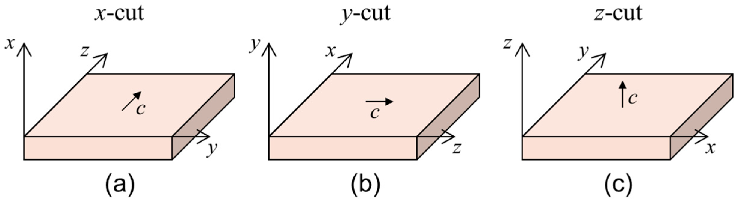
The bulk photovoltaic effect, basis of the PVT, is present in a number of non-centrosymmetric ferroelectric crystals such as LiNbO3. It relies on the directional photo-excitation of electronic carriers from donor centers, such as Fe2+, with a preferential momentum along the +c crystal direction, giving rise to an electric current. After migration of such carriers through the crystal lattice, and trapping at the corresponding impurity acceptors (Fe3+), a charge redistribution is achieved [23]. Consequently, an electric field (PV field), mainly along the ferroelectric axis (polar or c-axis), develops in the bulk of the crystal. It can reach very high values, up to 3 × 10⁵ V/cm for LiNbO3:Fe [13,24,25]. This bulk field extends outside the crystal (evanescent fields) allowing particle manipulation by the corresponding electrical forces [14,16]. The evanescent PV fields can be calculated from the bulk fields through the boundary conditions at the sample surface and have been numerically simulated for periodic and arbitrary light illumination profiles [26]. In that work, the crystal substrate had the polar axis parallel to the surface, x- or y-cut, (see Figure 2a,b). A recent work [27] includes a theoretical study for the same x-/y-cut geometry and using a very similar model than that of reference [26] but applied to a cylindrical light beam. Additionally, since 2013 another configuration with the polar axis normal to the surface, i.e., z-cut, (see Figure 2c) has been often employed in relation to 2D patterning (see Section 3) and a simple model to describe it has been already reported [28,29].
Micro- and nano-particles placed in the vicinity of the crystal sample experience dielectrophoretic forces fDEP for neutral particles and electrophoretic forces fEP for charged particles. Corresponding theoretical expressions are:
where q is the charge of the particle and the induced dipole moment is:
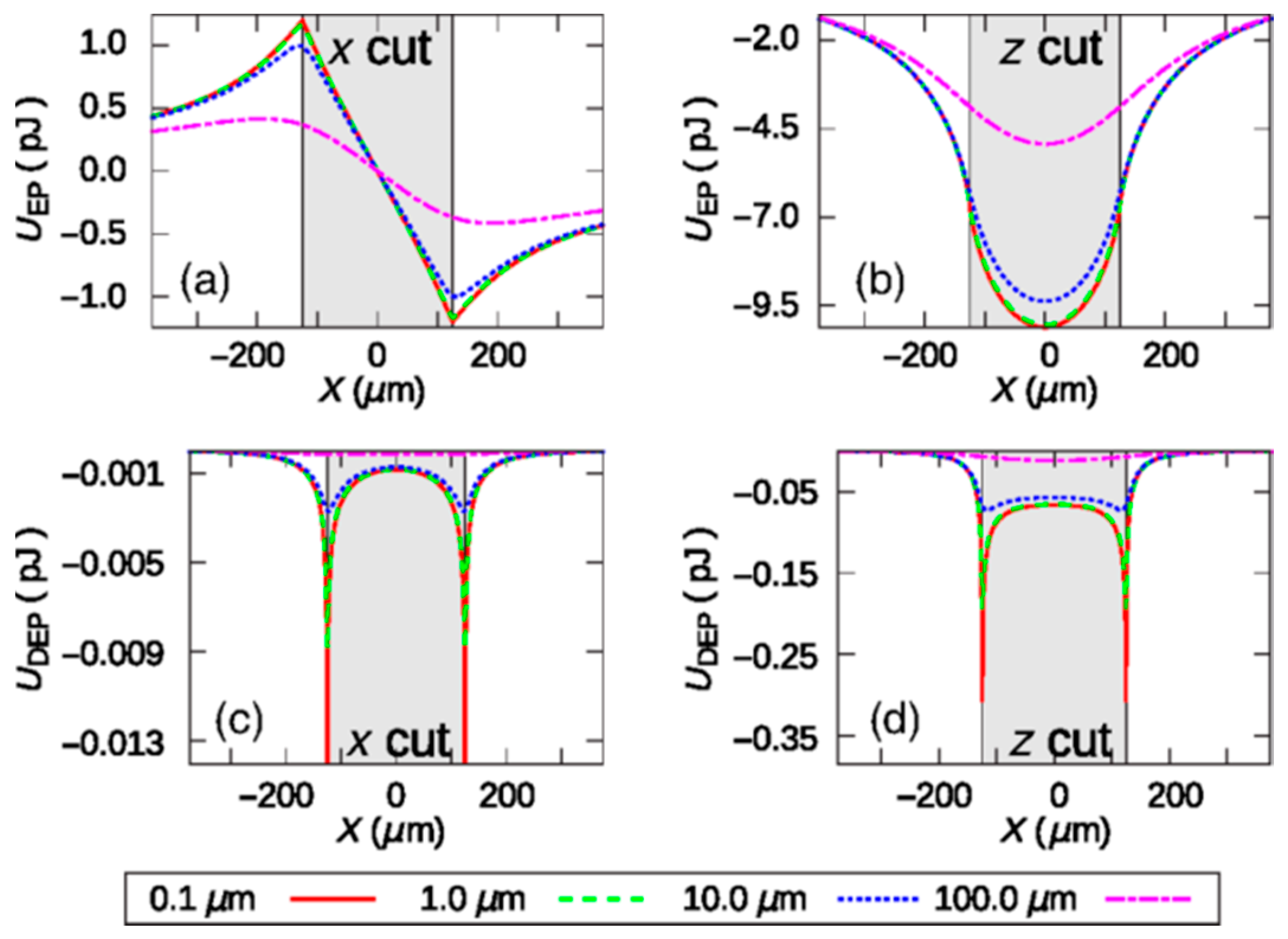
αij being the second-order polarizability tensor and ε0 the vacuum permittivity. In most theoretical works the authors find useful to use the DEP or EP potentials instead of the forces. Note that the possible contribution of both, EP and DEP forces, depending on the electrical charge of the particle, is a main difference with conventional optical tweezers, only acting through dielectrophoresis. Forces and potentials are essentially coupled to the fields near the surface of the LiNbO3 substrate and are quite different for x- or z-cut crystals. Most experiments performed so far have involved dielectrophoretic forces. However, experiments can be also carried out using charged particles. Moreover, in certain situations, particles initially neutral seem to become electrically charged during their path to the surface or after touching it [17]. Then, these experiments essentially operate under electrophoretic forces. This problem is, indeed, relevant and has been only recently addressed [19] by comparing on a quantitative basis the DEP and EP potentials at close distances from either the x-cut or z-cut crystal surfaces. The study shows clear differences in the expected particle density profiles obtained for the two cases and in both, x- and z-cut configurations. The differences are well illustrated in the simulations of Figure 3. Neutral particles show preferential trapping at the borderline of the light spot, whereas charged particles locate preferentially at the center and fade towards the edges. On the other side, the particle charging mechanisms, not yet well understood, are expected to be dependent on the electronic structure of the particle, the surrounding medium and the substrate crystal.
The polarizability tensor αij depends on both the dielectric constants of the particle εp and of the surrounding medium εm, due to local field effects [30]. For isotropic spherical particles of radius R under static PV fields or light fields with R << λ (Rayleigh approximation), the tensor becomes scalar and the induced polarization becomes [30],
According to (3) for metal particles which are illuminated under plasmon resonance conditions, εp + 2εm ≈ 0, thus the polarizability, α, and the induced dipole moment may reach very high values. Then, at those plasmon frequencies, strong enhancement effects in the linear and nonlinear optical properties can be achieved (see Section 3 and Section 5).
So far, most research and applications have focused on isotropic particles having scalar polarizabilities. However, recently, new results have been reported on the effect of the electrical torques acting on elongated particles and the possibility of inducing, not only their trapping, but also their alignment along the PV fields [21,31]. For anisotropic particles the tensor αij has, in principle, three different principal values along the three main perpendicular axes. For elongated (rod-shaped) particles having a dominant long z dimension (as for zeolite micro-cylinders in reference [31]), the main αzz component is:
The electrical torque τ associated to the PV field E is τ = p × E, whose modulus depends on the angle θ between the main particle axis and the field direction. Note that this torque operates throughout the whole trajectory of the particle path tending to align its main axis with the field during its approach to the active crystal surface. In reference [31] a rough simple estimate of the photovoltaic torque acting on elongated zeolites, ignoring local field effects, is calculated. For a typical PV field, E = 106 V/m, the maximum PV electrical torque value is τ ≈ 10−15 Nm. For comparison, the maximum gravity torque acting on the particle when it is touching the crystal surface, τG = mgl/2 (mg being the weight and l the length) is around 10−19 Nm, i.e., orders of magnitude lower.
Another subject deserving increasing attention of researchers refers to the manipulation of liquid microdroplets on photovoltaic substrates. This is particularly relevant for the rapidly expanding field of biomedical applications. Although in principle, the theoretical description follows the same scheme as for solid particles, some new concepts have to be considered such as surface tension and electrowetting [32]. Finally, theoretical approaches have focused on the steady state situation to describe the final particle density profiles after particles are trapped on the crystal surface. More research effort should be, indeed, devoted to the dynamics of the trapping process itself, including the approach to the surface and the competition with other interactions such as gravity, adhesion, and friction.
3. Manipulation of Micro- or Nanoparticles and Applications
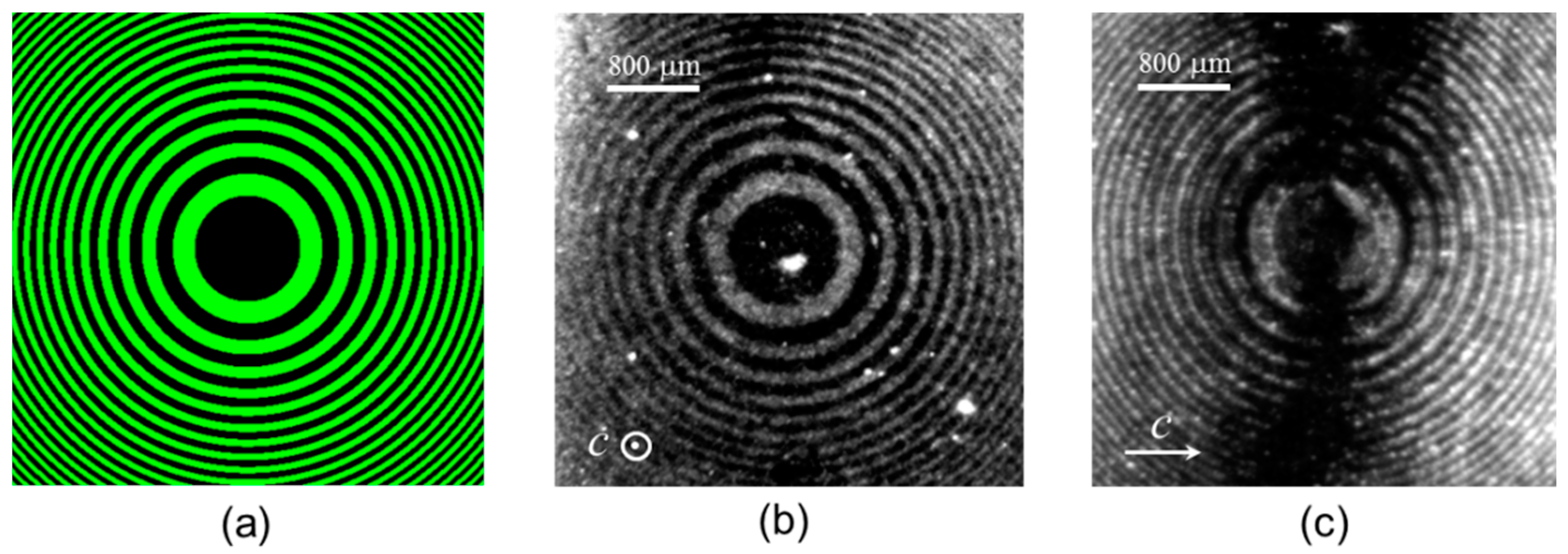
The first works on PVT reported their ability to trap and pattern micrometric particle [33,34] and it is in this subject where the field has reached a greater maturity. First experiments demonstrated the manipulation of dielectric and metallic micro- and nanoparticles using x- or y-cut lithium niobate crystals, i.e., substrates with the polar axis parallel to the surface [17,34]. The work was soon extended to 2D particle patterns still using x- or y-cuts. However, the particle structures presented the limitation that patterning along the direction parallel to the polar axis (z-axis) was not possible because electronic transport inside the crystal is along the z-axis, and thus the fields are also parallel to it (see [16] and references therein). An outstanding recent progress has been to use z-cut substrates, an unusual configuration for other photorefractive applications of LiNbO3. Figure 4 shows a comparison between DEP-induced particle structures obtained in z- (Figure 4b) and x-cut (Figure 4c) for the same 2D radial light pattern (Figure 4a). It can be clearly observed how z-cut substrates accurately reproduce the light pattern whereas x-cut cannot pattern the particles along lines parallel to the c-axis. The first work using z-cut was reported by Esseling et al. [18]. They used charged particles because they assumed that dielectrophoretic (DEP) forces acting on neutral particles were too weak in this configuration. Nevertheless, using highly doped crystals our group has demonstrated in a number of recent papers an excellent performance for 2D trapping with neutral inorganic micro- and nano-particles [19,29] and biological objects [22]. As previously mentioned, the experimental results have been accompanied with the development of a simple theoretical model for this configuration [28,29] that satisfactorily explains the experimental patterns. The comparison between electrophoretic and dielectrophoretic patterning which deals with charged and neutral particles respectively, is deeply investigated in reference [19] by theory and z-cut experiments. In that work significant differences in both particle density distribution and fidelity to the original light profile have been found. Moreover, these results provide a further confirmation of three key aspects concerning PVT operation: (i) The possibility of successful trapping of charged particles; (ii) the achievement of good quality 2D patterns; and (iii) the ability of the developed theory to explain the main EP and DEP observed phenomenology.
Another issue that deserves attention concerns the limits of the periodicities that can be achieved by PVT. Initially, the fabricated fringe particle patterns had periods in the range of 50–500 μm that later were reduced down to a few microns. In reference [35] an analysis on this subject is provided. The minimum periodicity recently reported [22] of 2 micrometers was obtained for a fringe pattern of pollen fragments although submicrometric periods should be achievable by using smaller particles. A related point is the maximum pattern resolution. In our experiments the minimum fringe thicknesses we have obtained so far are about 500–700 nm.
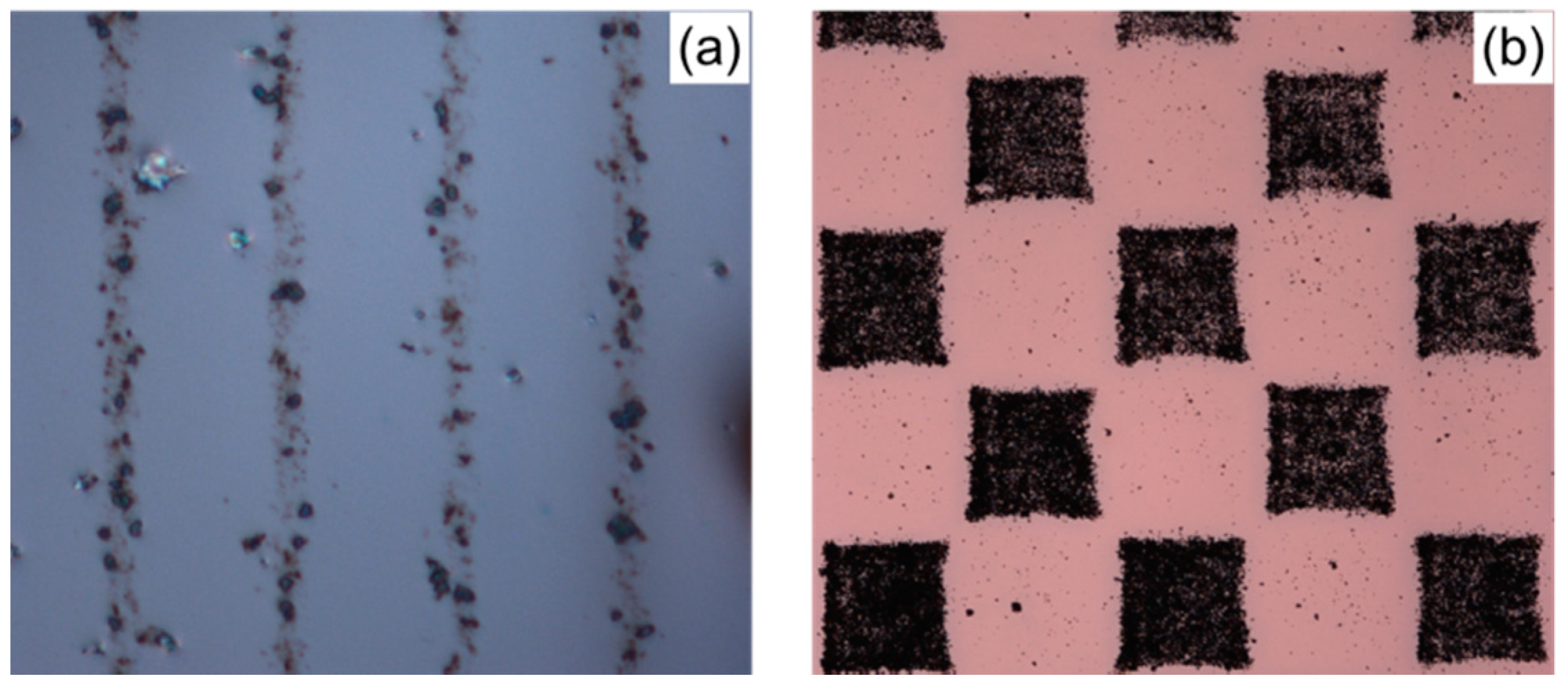
Both fringe patterns and 2D structures have been recently used for specific applications. On the one hand, fabrication of metal nanoparticle structures has been demonstrated and applied for plasmonic fluorescence (FL) enhancement from organic luminescent molecules [36,37]. In fact, a remarkable average enhancement factor of 10 is observed for disperse Red 1 organic molecules deposited on the 1D and 2D metallic patterns fabricated in a x- or z-cut substrate, respectively. Figure 5a shows a metallic fringe pattern of Ag nanoparticles with a period of 25 μm and Figure 5c the corresponding fluorescent intensity as a function of the position along a line perpendicular to the fringes. This latter curve shows an enhancement of one order of magnitude when the organic molecules are close to the Ag nanoparticle fringes. Similar results are obtained for a checkered Ag pattern and are shown in Figure 5b (nano-particle pattern) and Figure 5d (FL along a line normal to the square edge).
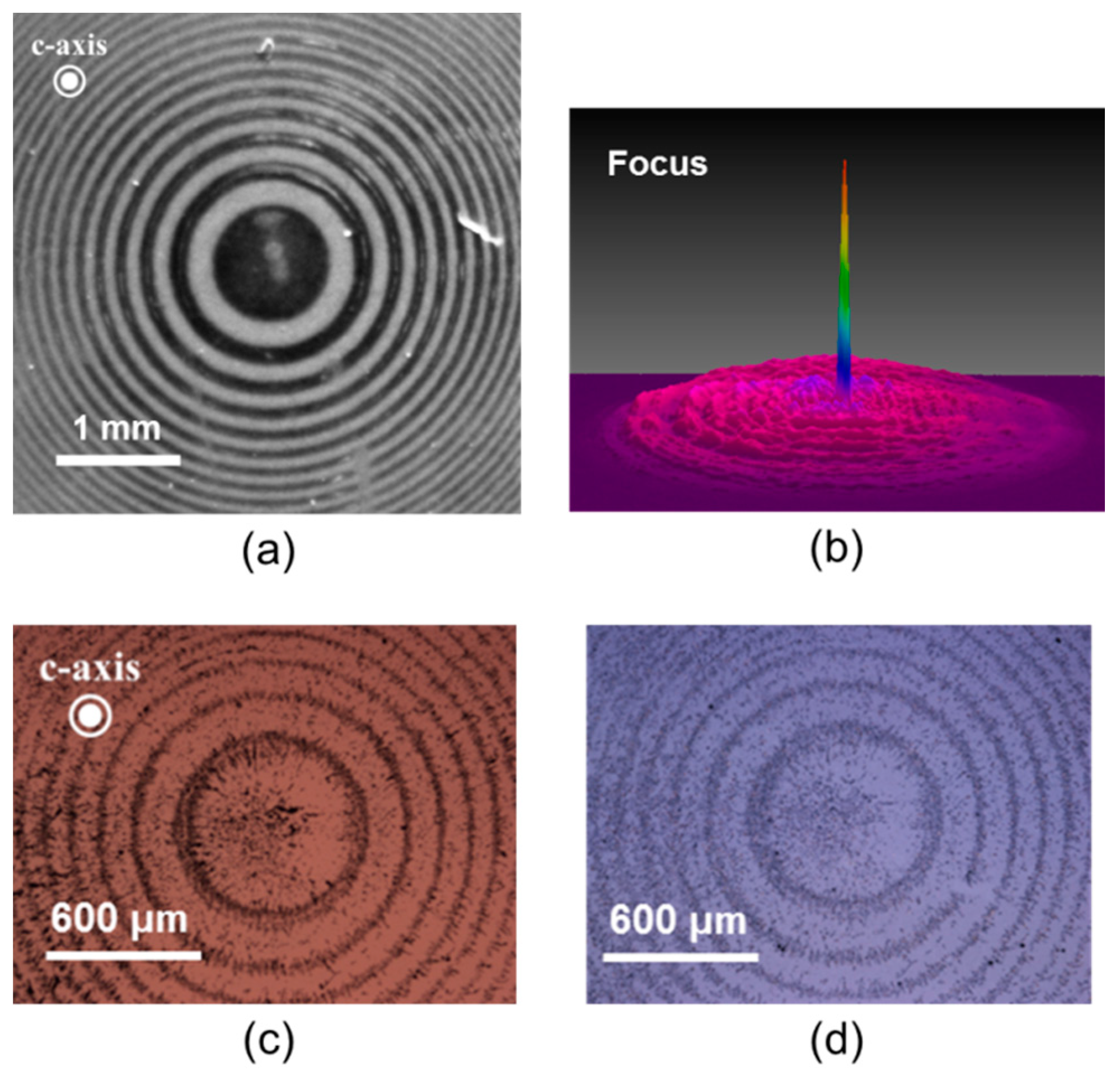
On the other hand, PVT have been used to fabricate photonic devices such as Fresnel lenses or diffraction gratings [38] by depositing Al nanoparticles on the lithium niobate substrate. In Figure 6a a photograph of the Fresnel zone plate is shown together (Figure 6b) with the light profile at the focus plane where the focusing capability can be clearly observed. The technique has been also applied to fabricate grating devices on lithium niobate waveguides [39]. Another relevant result that considerably enhances the applicability of particle patterns fabricated by PVT is the possibility of transferring the patterns to other substrates (glass, organic films) as it has been recently reported [36,38,39]. The result of such transferring method is illustrated in Figure 6c,d that shows the initial pattern on the lithium niobate substrate (Figure 6c) and the transferred pattern to a glass substrate (Figure 6d). It can be appreciated that the transferred replica faithfully reproduces the original pattern.
Finally, a work on the use of PVT for alignment of a large number of micro-cylinders (zeolites type L), either parallel or normal to the substrate surface, has been recently published [31]. The combined action of patterning and alignment is demonstrated. This new capability enhances the versatility of PVT that are becoming a unique tool to prepare functional microstructures useful in a variety of fields such as photonics (nonlinear optics, plasmonics [36]), nanochemistry [31] or microfluidics [40].
4. Droplet Manipulation
During the time period covered by this short review a few works were reported on the optoelectronic trapping and manipulation of liquid droplets on lithium niobate substrates. Most of them are based on the DEP forces generated by either the photovoltaic effect or a combination of photovoltaic and pyroelectric effects. Another work is based on surface wettability changes produced by the photovoltaic effect.
In 2015 Esseling et al. [40] presented a microfluidic device for droplet manipulation based on the action of dielectrophoretic forces controlled by virtual electrodes. The device was formed by a plastic structure of micro-channels on a z-cut LiNbO3:Fe crystal. An organic liquid containing droplets of another immiscible liquid was injected and pumped through the channels. The lithium niobate substrate was properly illuminated with the desired pattern to produce a surface electric field distribution by the photovoltaic effect. This electric field polarized the droplets and exerted on them dielectrophoretic forces. These authors demonstrated that for droplets with a dielectric constant higher than that of the surrounding liquid a repulsive DEP force appears. This effect was used to form stop barriers in the channel circuit to route the droplets. They also used micro air bubbles as droplets of dielectric constant lower than that of the liquid that transported them. They showed that in this case the DEP forces were attractive.
There is currently a great interest in the use of DEP forces for manipulating water droplets or micro- and nano-particles dispersed in water. This could open the way to the application of these techniques to the manipulation of biological samples. In fact, manipulating micro-scaled objects in water solution would be an important goal for future research on PVT, especially in biological applications.
Gazzeto et al. [27] reported in 2016 that they were not able to observe DEP force on dielectric particles dispersed in water or any aqueous solution. No trapping or repulsive DEP force was observed on micro-particles in aqueous medium. However, these authors also performed DEP manipulation experiments of water droplets using paraffin oil as the suspension liquid. They observed that positive DEP forces appeared acting on the water micro-droplets, and it was possible to achieve trapping regions in the upper and bottom side of the illuminated area.
A new strategy for microfluidic manipulation of dielectric liquid droplets based on the photovoltaic effect of lithium niobate is that presented by Chen et al. [41] in 2016. The device used by these authors consisted of a sandwich structure of two z-cut LiNbO3:Fe crystal plates separated by a distance of several microns. A dielectric liquid film of transformer oil, was introduced on the surface of the lower plate. A focused light beam was introduced perpendicular to the crystalline plates to generate a PV field on both surfaces. In a first stage the electric field modifies the surface of the liquid film producing a microdroplet in the form of a liquid bridge in contact with both plate surfaces. The micro-droplets sandwiched between the two lithium niobate substrates were affected by the DEP forces generated at both plates simultaneously, and could be moved by changing the light spot position. The form of the droplets could also be modified by using an illumination pattern. These authors performed also experiments on water micro-droplets with the same sandwich device, founding that the bridge between plates was not produced and no droplet movement was possible. Nevertheless, they pointed out that, after covering the substrate with a thin super hydrophobic film, the manipulation efficiency of water micro-droplets largely increases.
In a second paper, Chen et al. [42] extended the technique to droplet splitting using the same sandwich structure but introducing a combination of pyroelectric and photovoltaics effects. In this process a first step of heating and cooling the structure produced a pre-polarization of the dielectric oil droplet inside the sandwich by means of the pyroelectric effect of lithium niobate. In a second step the focused laser light induced a photovoltaic field concentrated on a part of the droplet. This field immobilized that portion of the microdroplet, while the surrounding part was repelled instantaneously resulting in droplet splitting.
Finally, Fan et al. [32] presented a remarkable work demonstrating water microdroplet manipulation by PVT. The innovation in this work is the coating of the LiNbO3:Fe substrate with a thin hydrophobic film. Using a focused light beam to induce a local photovoltaic field, the microdroplet placed on the hydrophobic film coating the substrate could be continuously transported by moving the light spot. It was observed that the droplet contact angle with the hydrophobic film was reduced when the laser beam was focused on the center of the droplet. However, when the light spot illuminates a droplet side asymmetric wetting appears giving rise to a force that could move the droplet (see Figure 7). This is explained by a wetting change produced by the photovoltaic electric field. However, the DEP force contribution cannot be fully ruled out. These authors consider that in the case of water microdroplets the main contribution to the manipulation is the electrowetting force. This work opens the possibility of manipulation of different kinds of aqueous biological microfluids by PVT, without the assistance of nonpolar dielectric liquid media.
Recently, Habibpourmoghadam et al. [43] presented related experiments on optical manipulation of liquid crystal (LC) films deposited on iron doped LiNbO3 substrates. In particular, these authors observed the modification of the edge shape of the LC film, induced by the motion of a light spot illuminating it. This observation is an additional example of the PVT action on a dielectric liquid (specifically a LC) although an in-depth study of the involved physical mechanisms is not available yet.
5. Biological PVT Applications
In the line of increasing the complexity of the investigated systems from pure fluidic systems, PVT have been successfully employed in the manipulation of biological materials and samples. Other approaches (pyroelectric or domain-polarization tweezers/surfaces), that also take advantage of ferroelectric properties, have been recently reported to successfully interact with different biological systems. However, dwelling in these will require broadening in excess the scope of this review. In consequence, we will not discuss here these similar methodologies, and will remain focused on strict biological applications of PVT and very closely related approaches. In what follows, we will present chronologically these results including pure trapping effects, structuring and patterning, and the first efforts to modulate living cells physiology and behavior.
The first report on the use of a ferroelectric substrate to obtain a pattern with biological molecules comes from Dunn et al., who in 2004 where able to preferentially arrange and organize particles from the tobacco mosaic virus over a PbZr0.3Ti0.7O3 (PZT) thin film [44]. The domain surface polarization was controlled by means of an atomic force microscope setup. Thus, the pattern was recorded not by light but using an external electric field, although the final result is practically the same. The interesting point is that the tweezing field was strong enough to efficiently trap the viral particles, but gentle enough to allow their spontaneous assembly into viral capsids.
Several years elapsed before new advancements in biological ferroelectric trapping were published. The first genuine approach to measure the direct effect of ferroelectrics on biological materials was done by our group. We published results that showed an efficient tumoral cell killing when HeLa cells were cultured on LiNbO3:Fe and then exposed to visible light [20]. Although not strictly a tweezing effect, the experiments can be understood as a derivation of the PVT, as we took advantage of the intense optically-induced PV field that exerts a strong influence on the cells. Several recent papers, focusing on the biological activity of ferroelectrics, claim that the possibility to grow cells on LiNbO3 has not been properly assessed until recently. However, our 2011 results clearly showed that HeLa cultures were stable and grew perfectly well for days on LiNbO3:Fe as long as they were kept in the dark. Under visible light illumination, however, cells quickly displayed morphological signs of plasma membrane damage and integrity loss. This led to cell death in a matter of minutes. Therefore, under conditions similar to, but more intense, than those routinely in use for PVT, eukaryotic cell death ensued. The physico-chemical and biological causes of this damage are under study. In a follow-up study we reported that submicrometric (100–200 nm) LiNbO3:Fe particles also had a deleterious effect on tumoral cells under visible light excitation [45]. However, the particles toxicity in the dark proved too high, and thus no further research was pursued in this area.
Recently, making use of pyroelectric field excitation, Grilli et al. were able to trap yeast cells on z-cut LiNbO3 [46]. The cell suspension was provided in paraffin oil. It is not explicitly stated in the article whatever the trapped cells were alive or dead, but given the experimental conditions (paraffin oil, temperatures in the range of 100 °C) it is presumable that the cells were dead. A subsequent report on biological shows that it is possible to trap and arrange different biological structures by making use of the PVT approach [16]. In particular, fungi spores (~10 µm) and pollen grains (~70 µm) and fragments thereof (~1–10 µm) were efficiently arranged following 1D (lines on x-cut LiNbO3:Fe) and 2D (checkered on z-cut LiNbO3:Fe) PV patterns previously inscribed in the LiNbO3:Fe substrate by optical means (see Figure 8). In this case, field excitation was due to the PVE excited with visible light (532 nm) and the biological materials were suspended in hexane to facilitate PVE action.
Presently, it has been possible to trap submicrometric pollen and spore fragments (50–150 nm, obtained by sonication) starting from a hexane solution [22]. Additionally, positive patterning results were also obtained from an air-dispersion of the biological particles, gently blown over the PVT substrate. In 1D patterns, record-breaking periods of 2 µm were obtained. In parallel, Miccio et al. [21] reported the trapping and orienting of live Escherichia coli bacteria over x-cut LiNbO3:Fe taking advantage of the PVE too. Different grating periods were optically recorded in the LiNbO3:Fe (12.5–100 µm). It was observed that most bacteria tended to orient perpendicular to the polarized domains, that is, parallel to the electric field gradient. It was argued by the authors that the bacteria (~0.5 × 2 µm rod-shaped) experience a torque as a consequence of the electric field pattern, which results in the specific cell orientation. This is remarkably remindful of previously mentioned results regarding the reorientation torque effects experienced by zeolite cylinders (1.5 × 4 µm) exposed to PVT (see Section 3 above). In an experimental breakthrough, these authors proved that biological patterning was possible under physiological conditions because the solvent employed for the bacterial trapping/orienting was water-based growth medium. Indeed, some preliminary results were shown where bacterial growth was possible for trapped and oriented bacteria.
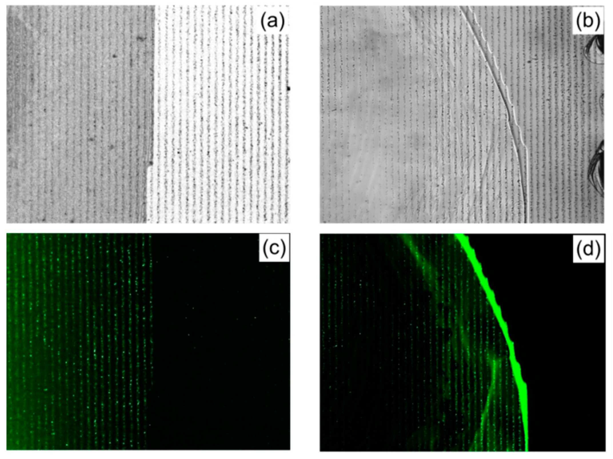
Finally, the possibility to combine PVT with other optical effects in biotechnological applications has been very recently reported [36]. There, the plasmonic enhancement of organic molecule fluorescence was efficiently modulated by PVT-driven patterns of silver nanoparticles. It is well known that certain phenomena, such as fluorescence, can be enhanced when a compound is very close to an optically-excited metallic nanostructure. This is because of the plasmonic effect, whereby the electric field associated to the electromagnetic wave is enhanced while interacting with the metal electrons (see Section 2). In our case, in order to induce the plasmonic effect, Ag nanoparticles of 25 nm were exposed to a 1D grating inscribed in an x-cut LiNbO3:Fe substrate. Once a linear Ag nanoparticle arrangement was obtained, the sample was incubated with either fluorescein-labeled DNA (200–500 bp) or fluorescein-labeled synthetic polymeric nucleic acids (PNA). The obtained results are shown in Figure 9, where the fluorescence emission enhancement is clear in the regions where Ag nanoparticles, trapped by the PVT, abound. Arguably, the fluorescein-tagged DNA or PNAs accumulated preferentially on the ordered Ag nanoparticles. Subsequent light excitation, enhanced by the Ag plasmonic effect, led to stronger green fluorescence of these ordered structures, as revealed by the images in Figure 9.
It is worth mentioning that biological trapping experiments with non-ferroelectric materials, that feature similar photoelectrical properties like GaN, are currently under development [47]. The effect is due to trapped charge carriers within the semiconductor lattice. Space charge relaxation kinetics is on the order of a few hours. In contrast, LiNbO3:Fe crystals sustain any photoinduced patterns for weeks or months, a remarkable advantage in comparison. Moreover, GaN requires UV light for charge carrier excitation, while LiNbO3:Fe requires only the much safer visible light to excite the PVE and trapping action.
6. Other Related Effects
In addition to the bulk photovoltaic effect, lithium niobate presents other phenomena also giving rise to internal electric fields, such as the pyroelectric and piezoelectric effects [15]. Then, a possible advantageous strategy could be to favorably combine these effects for manipulation purposes. In this direction, reference [42], already cited in Section 4, uses sequentially the pyroelectric and photovoltaic effects to efficiently split microdroplets. A different approach combining PV + PY effects has been applied to increase the versatility of the particle trapping methods and first results are reported in [48].
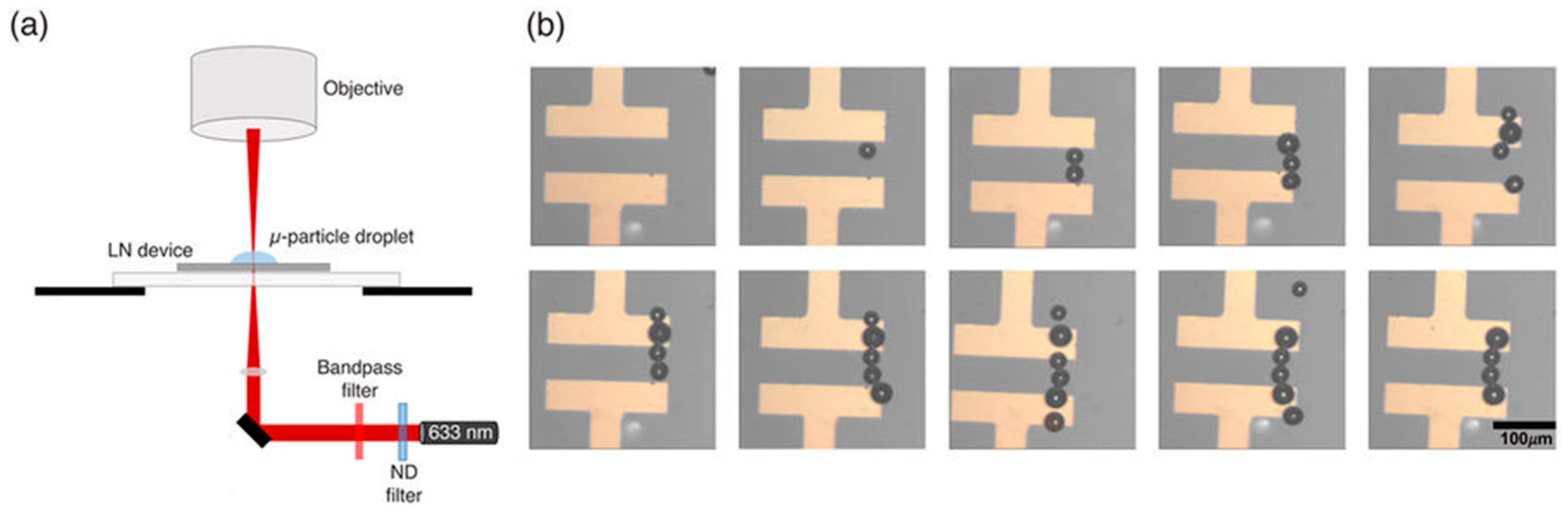
An interesting work by Sperling et al. [49] reports experiments playing with metallic micro-solder beads that represent a first stage to apply single particle manipulation for the fabrication of reconfigurable microelectronic circuitry (see Figure 10). It is remarkable that they efficiently used undoped LiNbO3 substrates instead of iron-doped ones. Although the PV mechanism is not discussed in detail in the paper, the generation of efficient PV fields in undoped crystals should involve intrinsic defects, which needs much higher intensities [50,51]. In fact, in this work the light intensities used (~2 kW/cm2) are substantially higher than the ordinary values (mW/cm2–W/cm2) employed in typical PVT experiments that use iron doped crystals.
Finally, another related subject, with increasing activity in the last two years, is concerned with the capability of the PV fields for the efficient reorientation of liquid crystals (LC). In this area, an interesting design strategy was advanced for the assembly of layered photoconductive-electrooptic devices [52]. It uses the evanescent PV fields (as in PV tweezers) generated in lithium niobate to transfer them into electrooptic layers such as LC films. More recently, Carns et al. [53,54] have demonstrated that the molecular director of LC assembled in-between two z-cut LiNbO3:Fe plates can be changed by the illumination of the cell with a low power laser beam. The light-induced reorientation phase shift has been characterized and controlled by the pump time illumination [55,56], allowing investigating the magnitude of PV fields induced in z-cut substrates [57]. The capability to change the direction of the molecular director by PV fields has been also used to produce locally reconfigurable defects with a focused low-power laser beam. Specifically, the formation of photo-induced localized defects has been investigated in detail, by experiments and simulations, in nematic LC [43,58] and chiral nematic (N*) LC [59], hybridized with z-cut iron doped lithium niobate substrates. The authors suggest that these results can be applied to generate complex photonic structures with micron accuracy, such as reconfigurable photonic patterns, or touch sensitive devices.
7. Summary and Outlook
The progress of the PVT technique, that we have briefly summarized, is remarkable indicating that it is becoming a very promising and simple method for micro- and nano-object manipulation. On the one hand, it allows massive nanoparticle trapping and patterning and so, the fabrication of functional nanostructures with application in photonics, plasmonics, nanotechnology, etc. In this sense, the recent reported works on the use of z-cut substrates definitely demonstrate the 2D patterning capabilities of PVT, either through electrophoretic or dielectrophoretic forces. On the other hand, the method is now progressing in the subject of droplet manipulation both in nonpolar and polar liquids, expanding its applications to the field of optofluidics. Finally, PVT are now finding promising applications in biotechnology and we foresee a rapid progression in this direction, not only in trapping but also in modulating living systems in vitro.
There are a number of challenges to enhance even more the PVT technological potential: (i) to extend the pattern resolution to the nanometer scale; (ii) to increase the reproducibility and control of the deposition process; and (iii) to satisfactorily manipulate and deposit particles in aqueous solutions, thus favoring progress in biotechnological applications. Further work in these directions should provide key advances in the near future.
Acknowledgments
This work was supported by MINECO, project number MAT2014-57704-C3-1-R. Alfonso Blázquez-Castro acknowledges funding under the Marie Skłodowska-Curie Action COFUND 2015 (EU project 713366–InterTalentum).
Conflicts of Interest
The authors declare no conflict of interest.
References
- Ashkin, A. Acceleration and trapping of particles by radiation pressure. Phy. Rev. Lett. 1970, 24, 156. [Google Scholar] [CrossRef]
- Ashkin, A.; Dziedzic, J.M.; Bjorkholm, J.E.; Chu, S. Observation of a single-beam gradient force optical trap for dielectric particles. Opt. Lett. 1986, 11, 288–290. [Google Scholar] [CrossRef] [PubMed]
- Ashkin, A. Forces of a single-beam gradient laser trap on a dielectric sphere in the ray optics regime. Biophys. J. 1992, 61, 569–582. [Google Scholar] [CrossRef]
- Woerdemann, M.; Gläsener, S.; Hörner, F.; Devaux, A.; De Cola, L.; Denz, C. Dynamic and reversible organization of zeolite L crystals induced by holographic optical tweezers. Adv. Mater. 2010, 22, 4176–4179. [Google Scholar] [CrossRef] [PubMed]
- Patgett, M.; Di Leonardo, R. Holographic optical tweezers and their relevance to lab on chip devices. Lab. Chip 2011, 11, 1196–1205. [Google Scholar] [CrossRef] [PubMed]
- Patgett, M.; Bowman, R. Tweezers with a twist. Nat. Photonics 2011, 5, 343–348. [Google Scholar] [CrossRef]
- Schiel, M.; Siwy, Z.S. Diffusion and trapping of single particles in pores with combined pressure and dynamic voltage. J. Phys. Chem. C 2014, 118, 19214–19223. [Google Scholar] [CrossRef]
- Pagliara, S.; Schwall, C.; Keyser, U.F. Optimizing diffusive transport through a synthetic membrane channel. Adv. Mater. 2013, 25, 844–849. [Google Scholar] [CrossRef] [PubMed]
- Pagliara, S.; Dettmer, S.L.; Keyser, U.F. Channel-facilitated diffusion boosted by particle binding at the channel entrance. Phys. Rev. Lett. 2014, 113, 048102. [Google Scholar] [CrossRef] [PubMed]
- Neves, A.A.R.; Camposeo, A.; Pagliara, S.; Sajia, R.; Borghese, F.; Denti, P.; Iatì, M.A.; Cingolani, R.; Maragò, O.M.; Pisignano, D. Rotational dynamics of optically trapped nanofibers. Opt. Express 2010, 18, 822–830. [Google Scholar] [CrossRef] [PubMed]
- Chiou, Y.; Ohta, T.A.; Wu, M.C. Massively parallel manipulation of single cells and microparticles using optical images. Nature 2005, 436, 370–372. [Google Scholar] [CrossRef] [PubMed]
- Glass, A.M.; von der Line, D.; Negran, T.J. High-voltage bulk photovoltaic effect and the photorefractive process in LiNbO3. Appl. Phys. Lett. 1974, 25, 233. [Google Scholar] [CrossRef]
- Sturmann, B.; Fridkin, V. Photovoltaic and Photorefractive Effects in Noncentosymetric Materials; Gordon and Breach Press: Philadelphia, PA, USA, 1992. [Google Scholar]
- Villarroel, J.; Burgos, H.; García-Cabañes, A.; Carrascosa, M.; Blázquez-Castro, A.; Agulló-López, F. Photovoltaic versus optical tweezers. Opt. Express 2011, 19, 24320–24330. [Google Scholar] [CrossRef] [PubMed]
- Arizmendi, L. Photonic applications of lithium niobate crystals. Phys. Stat. Solidi (a) 2004, 201, 253–283. [Google Scholar] [CrossRef]
- Carrascosa, M.; García-Cabañes, A.; Jubera, M.; Ramiro, J.B.; Agulló-López, F. LiNbO3: A photovoltaic substrate for massive parallel manipulation and patterning of nano-objects. Appl. Phys. Rev. 2015, 2, 040605. [Google Scholar] [CrossRef]
- Zhang, X.; Wang, J.; Tang, B.; Tan, X.; Rupp, R.A.; Pan, L.; Kong, Y.; Sun, Q.; Xu, J. Optical trapping and manipulation of metallic micro/nanoparticles via photorefractive crystals. Opt. Express 2009, 17, 9981–9988. [Google Scholar] [CrossRef] [PubMed]
- Esseling, M.; Zaltron, A.; Sada, C.; Denz, C. Charge sensor and particle trap based on z-cut lithium niobate. Appl. Phys. Lett. 2013, 103, 061115. [Google Scholar] [CrossRef]
- Muñoz-Martínez, J.F.; Ramiro, J.B.; Alcázar, A.; García-Cabañes, A.; Carrascosa, M. Electrophoretic vs. dielectrophoretic nanoparticle patterning using optoelectronic tweezers. Phys. Rev. Appl. 2017, 7, 064027. [Google Scholar] [CrossRef]
- Blázquez-Castro, A.; Stockert, J.C.; López-Arias, B.; Juarranz, A.; Agulló-López, F.; García-Cabañes, A.; Carrascosa, M. Tumour cell death induced by the bulk photovoltaic effect of LiNbO3:Fe under visible light irradiation. Photochem. Photobiol. Sci. 2011, 10, 956–963. [Google Scholar] [CrossRef] [PubMed]
- Miccio, L.; Marchesano, V.; Mugnano, M.; Grilli, S.; Ferraro, P. Light induced DEP for immobilizing and orienting Escherichia coli bacteria. Opt. Lasers Eng. 2016, 76, 34–39. [Google Scholar] [CrossRef]
- Jubera, M.; Elvira, I.; García-Cabañes, A.; Bella, J.L.; Carrascosa, M. Trapping and patterning of biological objects using photovoltaic tweezers. Appl. Phys. Lett. 2016, 108, 023703. [Google Scholar] [CrossRef]
- Agulló-López, F.; Calvo, G.F.; Carrascosa, M. Fundamentals of Photorefractive Phenomena. In Photorefractive Materials and Their Applications 1; Günter, P., Huignard, J.P., Eds.; Springer: New York, NY, USA, 2006; pp. 43–82. [Google Scholar]
- De Miguel, E.M.; Limeres, J.; Carrascosa, M.; Arizmendi, L. Study of developing thermal fixed holograms in lithium niobate. J. Opt. Soc. Am. B 2000, 17, 1140–1146. [Google Scholar] [CrossRef]
- Esseling, M.; Zaltron, A.; Argiolas, N.; Nava, G.; Imbrock, J.; Cristiani, I.; Sada, C.; Denz, C. Highly reduced iron-doped lithium niobate for optoelectronic tweezers. Appl. Phys. B 2013, 113, 191–197. [Google Scholar] [CrossRef]
- Arregui, C.; Ramiro, J.B.; Alcázar, A.; Méndez, A.; Burgos, H.; García-Cabañes, A.; Carrascosa, M. Optoelectronic tweezers under arbitrary illumination patterns: Theoretical simulations and comparison to experiment. Opt. Express 2014, 22, 29099–29110. [Google Scholar] [CrossRef] [PubMed]
- Gazzetto, M.; Nava, G.; Zaltron, A.; Cristiani, I.; Sada, C.; Minzioni, P. Numerical and Experimental Study of Optoelectronic Trapping on Iron-Doped Lithium Niobate Substrate. Crystals 2016, 6, 123. [Google Scholar] [CrossRef]
- Arregui, C.; Ramiro, J.B.; Alcázar, A.; Méndez, A.; Muñoz-Martínez, J.F.; Carrascosa, M. Comparative theoretical analysis between parallel and perpendicular geometries for 2D particle patterning in photovoltaic ferroelectric substrates. J. Eur. Opt. Soc. 2015, 10, 15026. [Google Scholar] [CrossRef]
- Muñoz-Martínez, J.F.; Elvira, I.; Jubera, M.; García-Cabañes, A.; Ramiro, J.B.; Arregui, C.; Carrascosa, M. Efficient photo-induced dielectrophoretic particle trapping on Fe:LiNbO3 for arbitrary two dimensional patterning. Opt. Mater. Express 2015, 5, 1137–1146. [Google Scholar] [CrossRef]
- Jones, T.B. Electromechanics of Particles; Cambridge University Press: Cambridge, UK, 1995. [Google Scholar]
- Elvira, I.; Muñoz-Martínez, J.F.; Barroso, A.; Denz, C.; Ramiro, J.B.; García-Cabañes, A.; Agulló-López, F.; Carrascosa, M. Massive ordering and alignment of cylindrical micro-objects by photovoltaic optoelectronic tweezers. Opt. Lett. 2018, 43, 30–33. [Google Scholar] [CrossRef] [PubMed]
- Fan, B.; Li, F.; Chen, L.; Shi, L.; Yan, W.; Zhang, Y.; Li, S.; Wang, X.; Chen, H. Photovoltaic Manipulation of Water Microdroplets on a Hydrophobic LiNbO3 Substrate. Phys. Rev. Appl. 2017, 7, 064010. [Google Scholar] [CrossRef]
- Sarkisov, S.S.; Curley, M.J.; Kukhtarev, N.V.; Fields, A.; Adamovsky, G.; Smith, C.C.; Moore, L.E. Holographic surface gratings in iron-doped lithium niobate. Appl. Phys. Lett. 2001, 79, 901–903. [Google Scholar] [CrossRef]
- Eggert, H.A.; Kuhnert, F.Y.; Buse, K.; Adleman, J.R.; Psaltis, D. Trapping of dielectric particles with light-induced space-charge fields. Appl. Phys. Lett. 2007, 90, 241909. [Google Scholar] [CrossRef]
- Matarrubia, J.; García-Cabañes, A.; Plaza, J.L.; Agulló-López, F.; Carrascosa, M. Optimization of particle trapping and patterning via photovoltaic tweezers: Role of light modulation and particle size. J. Phys. D Appl. Phys. 2014, 47, 265101. [Google Scholar] [CrossRef]
- Elvira, I.; Muñoz-Martínez, J.F.; Jubera, M.; García-Cabañes, A.; Bella, J.L.; Haro-González, P.; Díaz-García, M.A.; Agulló-López, F.; Carrascosa, M. Plasmonic Enhancement in the Fluorescence of Organic and Biological Molecules by Photovoltaic Tweezing Assembly. Adv. Mater. Technol. 2017, 2, 1700024. [Google Scholar] [CrossRef]
- Muñoz-Martínez, J.F.; Alcázar, A.; Elvira, I.; Ramiro, J.; García-Cabañes, A.; Arizmendi, A.; Carrascosa, M. Optoelectronic tweezers based on photorefractive space fields: Recent achievements and challenges. J. Phys. Conf. Ser. 2017, 867, 012030. [Google Scholar] [CrossRef]
- Muñoz-Martínez, J.F.; Jubera, M.; Matarrubia, J.; García-Cabañes, A.; Agulló-López, F.; Carrascosa, M. Diffractive optical devices produced by light-assisted trapping of nanoparticles. Opt. Lett. 2016, 41, 432–435. [Google Scholar] [CrossRef] [PubMed]
- Muñoz-Martínez, J.F.; Martín, G.; Alcázar, A.; Carrascosa, M. Nanoparticle Gratings for Compact Spectrometers: An Application of Photovoltaic Tweezers. J. Phys. Conf. Ser. 2017, 867, 012032. [Google Scholar] [CrossRef]
- Esseling, M.; Zaltron, A.; Horn, W.; Denz, C. Optofluidic droplet router. Laser Photonics Rev. 2015, 9, 98–104. [Google Scholar] [CrossRef]
- Chen, L.; Li, S.; Fan, B.; Yan, W.; Wang, D.; Shi, L.; Chen, H.; Ban, D.; Sun, S. Dielectrophoretic behaviours of microdroplet sandwiched between LN substrates. Sci. Rep. 2016, 6, 29166. [Google Scholar] [CrossRef] [PubMed]
- Chen, L.; Fan, B.; Yan, W.; Li, S.; Shi, L.; Chen, H. Photo-assisted splitting of dielectric microdroplets in a LN-based sandwich structure. Opt. Lett. 2016, 41, 4558–4561. [Google Scholar] [CrossRef] [PubMed]
- Habibpourmoghadam, A.; Jiao, L.; Reshetnyak, V.; Evans, D.R.; Lorenz, A. Optical manipulation and defect creation in a liquid crystal on a photoresponsive surface. Phys. Rev. E 2017, 96, 022701. [Google Scholar] [CrossRef] [PubMed]
- Dunn, S.; Cullen, D.; Abad-Garcia, E.; Bertoni, C.; Carter, R.; Howorth, D.; Whatmore, R.W. Using the surface spontaneous depolarization field of ferroelectrics to direct the assembly of virus particles. Appl. Phys. Lett. 2004, 85, 3537–3539. [Google Scholar] [CrossRef]
- Carrascosa, M.; García-Cabañes, A.; Jubera, M.; Elvira, I.; Burgos, H.; Bella, J.L.; Agulló-López, F.; Muñoz-Martínez, J.F.; Alcázar, A. Photovoltaic tweezers an emergent tool for applications in nano and bio-technology. In Proceedings of the SPIE Optical Methods for Inspection, Characterization, and Imaging of Biomaterials, Munich, Germany, 21–25 June 2015; Volume 9529. [Google Scholar]
- Grilli, S.; Coppola, S.; Nasti, G.; Vespini, V.; Gentile, G.; Ambrogi, V.; Carfagna, C.; Ferraro, P. Hybrid ferroelectric-polymer microfluidic device for dielectrophoretic self-assembling of nanoparticles. RSC Adv. 2014, 4, 2851–2857. [Google Scholar] [CrossRef]
- Snyder, P.J.; Kirste, R.; Collazo, R.; Ivanisevic, A. Persistent photoconductivity, nanoscale topography, and chemical functionalization can collectively influence the behavior of PC12 cells on wide bandgap semiconductor surfaces. Small 2017, 13, 1700481. [Google Scholar] [CrossRef] [PubMed]
- Faba, J.; Puerto, A.; Muñoz-Martínez, J.F.; Méndez, A.; Alcazar, A.; García-Cabañes, A.; Carrascosa, M. Nanoparticle manipulation and trapping by the synergy between the photovoltaic and pyroelectric effects. J. Phys. Conf. Ser. 2017, 867, 012038. [Google Scholar] [CrossRef]
- Sperling, J.R.; Neale, S.L.; Clark, A.W. Bridging the gap: Rewritable electronics using real-time light-induced dielectrophoresis on lithium niobate. Sci. Rep. 2017, 7, 9660. [Google Scholar] [CrossRef] [PubMed]
- Carnicero, J.; Caballero, O.; Carrascosa, M.; Cabrera, J.M. Superlinear photovoltaic currents in LiNbO3: Analyses under the two-center model. Appl. Phys. B 2004, 79, 351–358. [Google Scholar] [CrossRef]
- Carrascosa, M.; Villarroel, J.; Carnicero, J.; García-Cabañes, A.; Cabrera, J.M. Understanding light intensity thresholds for catastrophic optical damage in LiNbO3. Opt. Express 2008, 16, 115–120. [Google Scholar] [CrossRef] [PubMed]
- Aguilar, M.; Carrascosa, M.; Agulló-López, F. An alternative design strategy for photorefractive polymer films. Adv. Mater. 1997, 9, 423–426. [Google Scholar]
- Carns, J.L.; Cook, G.; Saleh, M.A.; Serak, S.V.; Tabiryan, N.V.; Evans, D.R. Self-activated liquid-crystal cells with photovoltaic substrates. Opt. Lett. 2006, 31, 993–995. [Google Scholar] [CrossRef] [PubMed]
- Carns, J.L.; Cook, G.; Saleh, M.A.; Serak, S.V.; Tabiryan, N.V.; Basun, S.A.; Evans, D.R. Photovoltaic field-induced self-phase modulation of light in liquid crystal cells. Mol. Cryst. Liq. Cryst. 2006, 453, 83–92. [Google Scholar] [CrossRef]
- Lucchetti, L.; Kushnir, K.; Zaltron, A.; Simoni, F. Light controlled phase shifter for optofluidics. Opt. Lett. 2016, 41, 333–335. [Google Scholar] [CrossRef] [PubMed]
- Lucchetti, L.; Kushnir, K.; Zaltron, A.; Simoni, F. Liquid crystal cells based on photovoltaic substrates. J. Eur. Opt. Soc. 2016, 11, 16007. [Google Scholar] [CrossRef]
- Lucchetti, L.; Kushnir, K.; Reshetnyak, V.; Ciciulla, F.; Zaltron, A.; Sada, C.; Simoni, F. Light-induced electric field generated by photovoltaic substrates investigated through liquid crystal reorientation. Opt. Mater. 2017, 73, 64–69. [Google Scholar] [CrossRef]
- Habibpourmoghadam, A.; Jiao, L.; Omairat, F.; Evans, D.R.; Lucchetti, L.; Reshetnyak, V.; Lorenz, A. Confined photovoltaic fields in a photo-responsive liquid crystal test cell. In Proceedings of the Liquid Crystals XXI, San Diego, CA, USA, 6–10 August 2017; Volume 10361. [Google Scholar]
- Habibpourmoghadam, A.; Lucchetti, L.; Evans, D.R.; Jiao, L.; Reshetnyak, V.; Omairat, F.; Schafforz, S.L.; Lorenz, A. Laser-induced erasable patterns in a N* liquid crystal on an iron doped lithium niobate surface. Opt. Express 2017, 25, 26148–26159. [Google Scholar] [CrossRef] [PubMed]
Figure 1.
Schematics showing the operation of photovoltaic tweezers: (a) Illumination of the PV substrate; (b) approach of the particles to the substrate under DEP or EP forces; and (c) resulting trapped particle pattern. Steps (a) and (b) can be performed either sequentially or simultaneously.
Figure 1.
Schematics showing the operation of photovoltaic tweezers: (a) Illumination of the PV substrate; (b) approach of the particles to the substrate under DEP or EP forces; and (c) resulting trapped particle pattern. Steps (a) and (b) can be performed either sequentially or simultaneously.
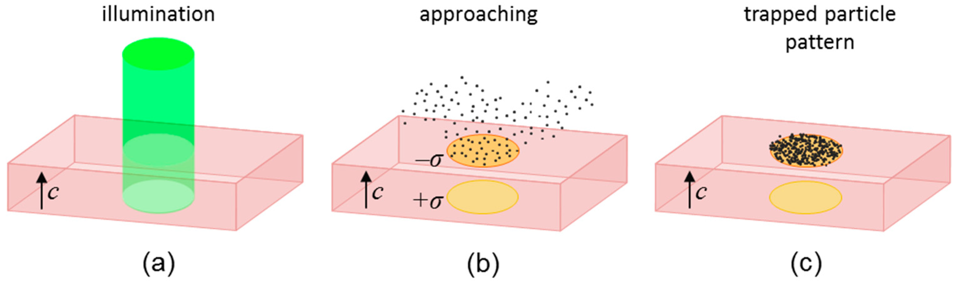
Figure 2.
Different orientations of the PV substrate with the polar c-axis parallel to the active surface (a,b) or perpendicular to it (c). Note that the c-axis is taken always along the z direction.
Figure 2.
Different orientations of the PV substrate with the polar c-axis parallel to the active surface (a,b) or perpendicular to it (c). Note that the c-axis is taken always along the z direction.

Figure 3.
EP (a,b) and DEP (c,d) potentials due to a single square illumination in x-cut (a,c) and z-cut (b,d). Potentials are calculated at the central plane of the square, perpendicular to the crystal and at different distances from the surface, 0.1, 1.0, 10.0 and 100.0 µm, as indicated in the legend. In z-cut, potentials are calculated on the c+ crystal face. Reprinted with permission from Martínez-Muñoz et al. Phys. Rev. Appl. 2017, 7, 064027. Copyright 2017 American Physical Society (reference [19]).

Figure 4.
Light pattern illuminating the substrate (a), and corresponding CaCO3 micro-particle (average diameter ~2 μm) patterns for z-cut (b) and x-cut (c) LiNbO3:Fe substrates. The direction of the crystal c-axis is indicated in (b,c). Reprinted with permission from Martínez-Muñoz et al. Opt. Mater. Express 2015, 5, 1137. Copyright 2015 Optical Society of American (reference [29]).

Figure 5.
Fluorescence microphotographs of (a) a 1D fringe pattern and (b) a 2D checkered pattern. (c,d) show the corresponding micro-luminescence profiles of a region in the patterns. Taken from Martínez-Muñoz et al. J. Phys. Conf. Ser. 2017, 867, 012030 (reference [37]).
Figure 5.
Fluorescence microphotographs of (a) a 1D fringe pattern and (b) a 2D checkered pattern. (c,d) show the corresponding micro-luminescence profiles of a region in the patterns. Taken from Martínez-Muñoz et al. J. Phys. Conf. Ser. 2017, 867, 012030 (reference [37]).
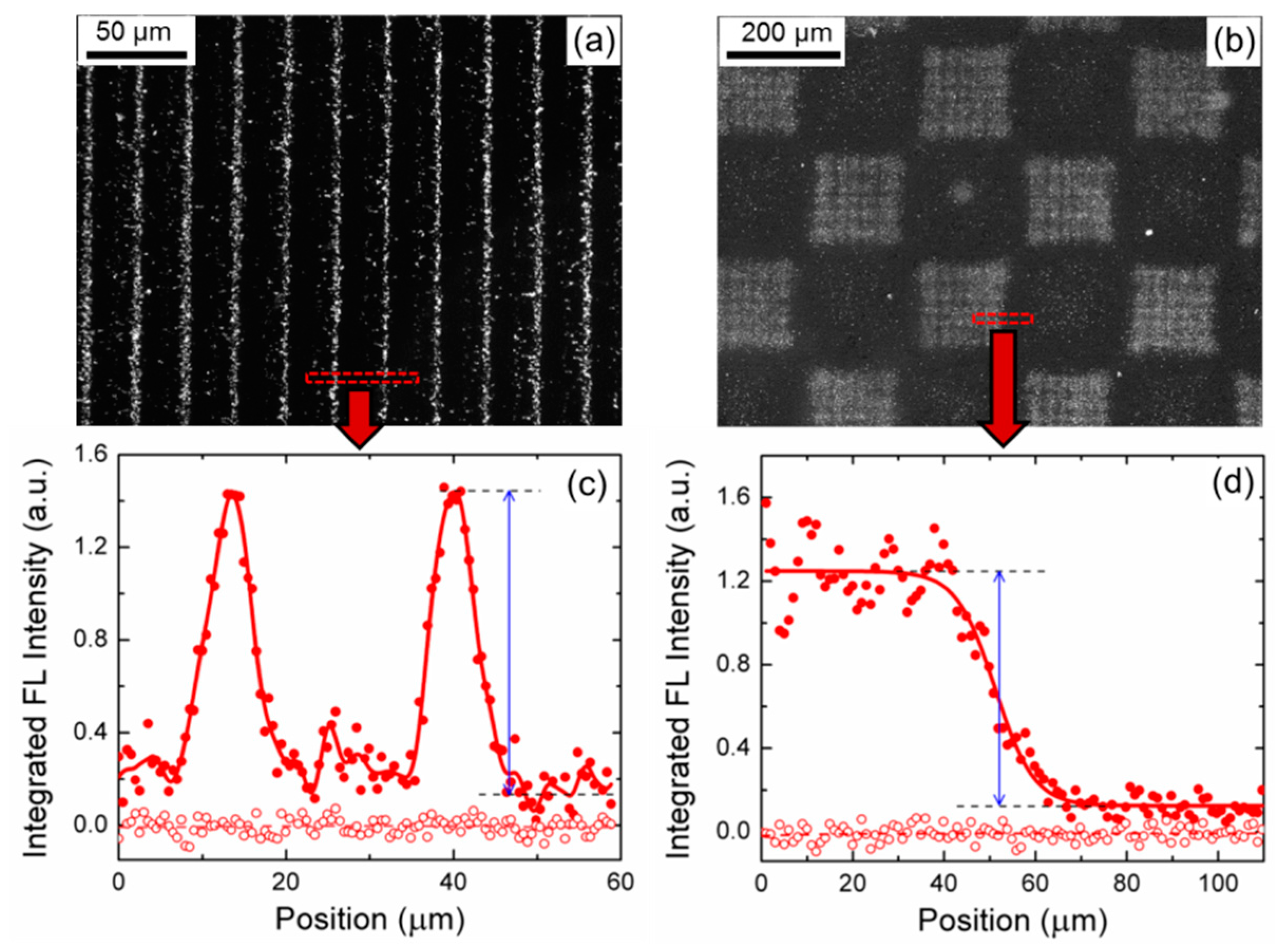
Figure 6.
(a) Photography of a Fresnel lens fabricated with Al nanoparticles (d~70 nm), and (b) intensity profile of the diffracted light along a transversal direction at the focus acting as zone plate. (c) Microscopic image of a Fresnel pattern of Al nanoparticles on the LiNbO3:Fe and (d) this pattern transferred to a glass substrate. Reprinted with permission from Martínez-Muñoz et al. Opt. Lett. 2016, 41, 432. Copyright 2016 Optical Society of American (reference [38]).

Figure 7.
Schematic side view (a) and top photographs (b) of the micro-droplet deformation under the limbic laser illumination on the hydrophobic substrate. Reprinted with permission from Fan et al. Phys. Rev. Appl. 2017, 7, 064010. Copyright 2017 American Physical Society (reference [32]).
Figure 7.
Schematic side view (a) and top photographs (b) of the micro-droplet deformation under the limbic laser illumination on the hydrophobic substrate. Reprinted with permission from Fan et al. Phys. Rev. Appl. 2017, 7, 064010. Copyright 2017 American Physical Society (reference [32]).
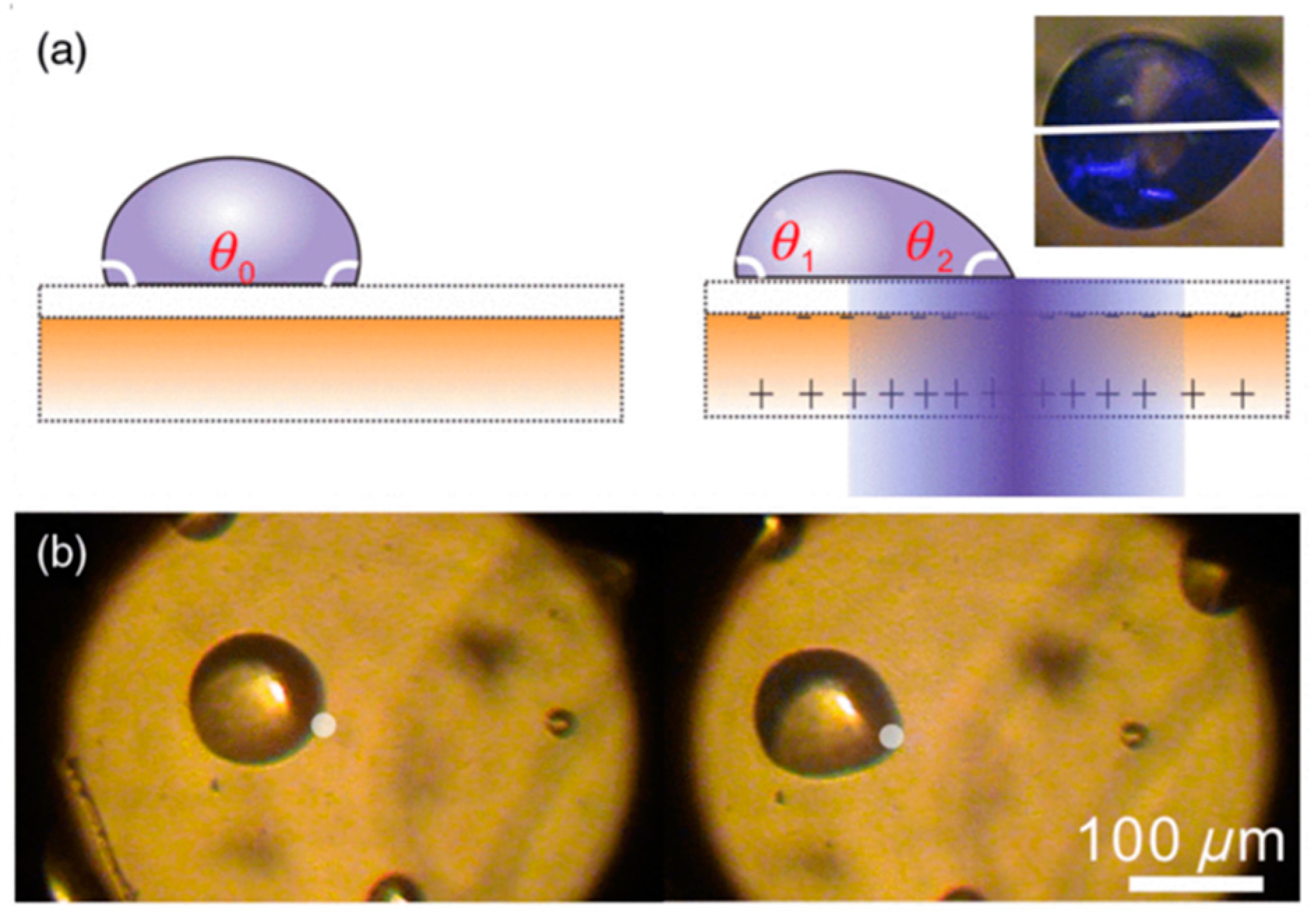
Figure 8.
Optical microscope images of 1D fringes (Λ = 14 μm) (a) and 2D square (side 200 μm) (b) patterns of nanometric spore and pollen fragments on x-cut and z-cut LiNbO3:Fe crystals, respectively. Taken from Martínez-Muñoz et al. J. Phys. Conf. Ser. 2017, 867, 012030 (reference [37]).
Figure 8.
Optical microscope images of 1D fringes (Λ = 14 μm) (a) and 2D square (side 200 μm) (b) patterns of nanometric spore and pollen fragments on x-cut and z-cut LiNbO3:Fe crystals, respectively. Taken from Martínez-Muñoz et al. J. Phys. Conf. Ser. 2017, 867, 012030 (reference [37]).

Figure 9.
Optical microscope images (a,b), and FL microscope images (c,d), showing two droplets of fluorescein labelled biomolecules deposited on an Ag-nanoparticle periodic pattern: DNA for (a,c) and synthetic peptide for (b,d) solution droplets. Reprinted with permission from Elvira et al. Adv. Mater. Technol. 2017, 2, 1700024. Copyright 2017 John Wiley and Sons (reference [36]).

Figure 10.
Schematic of the experimental setup (a), and demonstration (b) of one-by-one micro-solder-bead assembly between two gold electrodes deposited on z-cut LiNbO3 crystal. Taken from Sperling et al. Sci. Rep. 2017, 7, 9660 (reference [49]).
Figure 10.
Schematic of the experimental setup (a), and demonstration (b) of one-by-one micro-solder-bead assembly between two gold electrodes deposited on z-cut LiNbO3 crystal. Taken from Sperling et al. Sci. Rep. 2017, 7, 9660 (reference [49]).

© 2018 by the authors. Licensee MDPI, Basel, Switzerland. This article is an open access article distributed under the terms and conditions of the Creative Commons Attribution (CC BY) license (http://creativecommons.org/licenses/by/4.0/).
Share and Cite
MDPI and ACS Style
García-Cabañes, A.; Blázquez-Castro, A.; Arizmendi, L.; Agulló-López, F.; Carrascosa, M. Recent Achievements on Photovoltaic Optoelectronic Tweezers Based on Lithium Niobate. Crystals 2018, 8, 65. https://doi.org/10.3390/cryst8020065
AMA Style
García-Cabañes A, Blázquez-Castro A, Arizmendi L, Agulló-López F, Carrascosa M. Recent Achievements on Photovoltaic Optoelectronic Tweezers Based on Lithium Niobate. Crystals. 2018; 8(2):65. https://doi.org/10.3390/cryst8020065
Chicago/Turabian StyleGarcía-Cabañes, Angel, Alfonso Blázquez-Castro, Luis Arizmendi, Fernando Agulló-López, and Mercedes Carrascosa. 2018. "Recent Achievements on Photovoltaic Optoelectronic Tweezers Based on Lithium Niobate" Crystals 8, no. 2: 65. https://doi.org/10.3390/cryst8020065
Note that from the first issue of 2016, this journal uses article numbers instead of page numbers. See further details here.